XIAO RP2040 MicroPython Setup & Troubleshooting Guide
Session Summary
This document summarizes a hands-on learning session for setting up and programming the XIAO RP2040 microcontroller with MicroPython, including common pitfalls and solutions.
1. Understanding BOOTSEL Mode
What is BOOTSEL Mode?
- BOOTSEL = BOOTloader SELection mode
- Special startup mode where the RP2040 acts as a USB flash drive
- Appears as a mounted drive named "RPI-RP2"
- Used to install firmware by drag-and-drop of
.uf2files
How to Enter BOOTSEL Mode
- Hold the BOOT button while plugging in USB cable, OR
- Double-press the RESET button quickly
BOOTSEL vs Normal Programming
- BOOTSEL mode: Direct firmware flashing (MicroPython, CircuitPython, bootloaders)
- Normal programming: Upload code via serial (Arduino IDE, Thonny, mpremote)
- Both write to the same flash memory (non-volatile storage)
What You See in BOOTSEL Mode
After successfully installing MicroPython firmware:
- The .uf2 file disappears (consumed during flashing)
- Two files appear: INDEX.HTM and INFO_UF2.TXT
- These are virtual files generated by the bootloader
- Board automatically reboots into MicroPython
2. Memory Types on RP2040
SRAM (Volatile) - 264KB
- Fast, temporary memory
- Loses data when powered off
- Used for variables, stack, heap during program execution
Flash (Non-volatile) - 2MB on XIAO RP2040
- Permanent storage
- Retains data when powered off
- Stores program code, libraries, and data files
3. Reset Button vs Unplug/Replug
Reset Button (R)
- Restarts the RP2040 chip
- Power stays on
- USB connection often remains active
- Faster for development workflow
- Good for: restarting programs, quick testing
Unplug/Replug
- Complete power cycle
- Full hardware reset
- USB fully disconnects and reconnects
- Good for: stuck USB states, exiting BOOTSEL mode, weird behavior
For most development: Reset button is sufficient
For troubleshooting: Unplug/replug provides a cleaner slate
4. VS Code Tasks Configuration
Understanding tasks.json
Created a VS Code task for automated MicroPython uploads:
{
  "version": "2.0.0",
  "tasks": [
    {
      "label": "Upload to Pico",
      "type": "shell",
      "command": "mpremote connect auto fs cp main.py : + reset",
      "group": "build",
      "presentation": {
        "reveal": "always",
        "panel": "shared"
      }
    }
  ]
}
Key Components Explained
mpremote: MicroPython remote control toolconnect auto: Auto-detect the RP2040fs cp main.py :: Copy file to board's root directory+ reset: Chain command to soft-reset the board[]brackets: JSON array (required even for single task){}braces: JSON object (key-value pairs)
Prerequisites
Install mpremote:
pip install mpremote
5. JSON File Format
What is JSON?
- JSON = JavaScript Object Notation
- Plain text format for structured data
- Human-readable and machine-parseable
- Language-independent
JSON Syntax
{}= Object (key-value pairs, like a dictionary)[]= Array (ordered list of items)- Keys must be in double quotes
- No trailing commas allowed
Common Uses
- Configuration files (VS Code, Arduino)
- Data storage (sensor readings, settings)
- API communication
- MicroPython config files
6. First MicroPython Code - LED Blinking
Initial Code (Had Issues)
from machine import Pin
import time

print("Hello World")
led = Pin(6, Pin.OUT)

t = 10
off = 0.5
slow = 1.5
quick = 0.5

while t > 1:
    led.toggle()
    time.sleep(off)
    led.toggle()
    time.sleep(slow)
    led.toggle()
    time.sleep(off)
    led.toggle()
    time.sleep(quick)
    led.toggle()
    time.sleep(off)
    led.toggle()
    time.sleep(quick)
    t -= 1
Problem Encountered
- Code logic was correct
- Onboard LED worked fine
- External LED did not light up
7. Troubleshooting External LED
Common Hardware Issues Identified
Issue 1: LED Polarity
LEDs only work in one direction: - Anode (+): Long leg, connects to resistor/pin - Cathode (-): Short leg, flat side, connects to GND - Solution: Flip LED 180° if backwards
Issue 2: Missing/Wrong Resistor
- Need 220Ω - 1kΩ current-limiting resistor
- Correct wiring: Pin → Resistor → LED+ → LED- → GND
Issue 3: Incomplete Circuit
- LED cathode must connect to GND pin on XIAO
- Circuit must be complete for current flow
Issue 4: Wrong Pin Number (THE ACTUAL PROBLEM!)
- XIAO RP2040 silkscreen labels don't match GPIO numbers
- Board label D6 = GPIO 0 in code
- This was the root cause of the LED not working
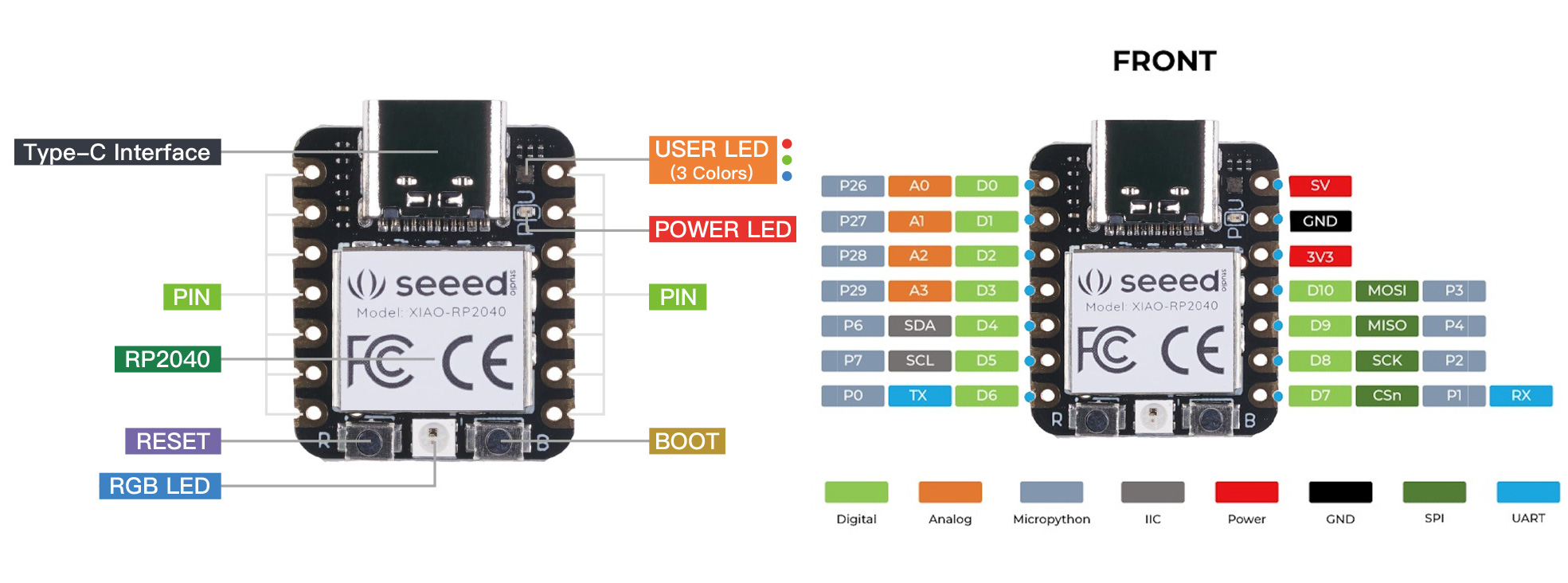
8. XIAO RP2040 Pin Mapping (Critical!)
The Confusion
The XIAO RP2040 has misleading silkscreen labels. You must translate:
| Board Label | Use in Code | Notes |
|---|---|---|
| D0 | Pin(26) |
Also ADC0 |
| D1 | Pin(27) |
Also ADC1 |
| D2 | Pin(28) |
Also ADC2 |
| D3 | Pin(29) |
Also ADC3 |
| D4 | Pin(6) |
|
| D5 | Pin(7) |
|
| D6 | Pin(0) |
← Common mistake! |
| D7 | Pin(1) |
|
| D8 | Pin(2) |
|
| D9 | Pin(4) |
|
| D10 | Pin(3) |
Special Pins
- Onboard LED:
Pin(25)orPin(16),Pin(17)for RGB components - NeoPixel Power:
Pin(11) - NeoPixel Data:
Pin(12)
Best Practice
Always comment your code with both labels:
# D6 = GPIO 0
led = Pin(0, Pin.OUT)
9. Running Multiple LEDs
Method 1: Two Separate Pins (Simplest)
from machine import Pin
import time

led1 = Pin(26, Pin.OUT)  # D0
led2 = Pin(27, Pin.OUT)  # D1

# Both on
led1.on()
led2.on()
time.sleep(1)

# Both off
led1.off()
led2.off()
Method 2: Alternating Pattern
while True:
    led1.on()
    led2.off()
    time.sleep(0.5)

    led1.off()
    led2.on()
    time.sleep(0.5)
Method 3: Using Lists (Scalable)
leds = [
    Pin(26, Pin.OUT),
    Pin(27, Pin.OUT),
    Pin(28, Pin.OUT),
]

# Toggle all
for led in leds:
    led.toggle()
Hardware Requirements
Each LED needs: - Its own GPIO pin - Its own current-limiting resistor (220Ω - 1kΩ) - Connection to GND (can share common GND)
10. Key Lessons Learned
Technical Insights
- BOOTSEL mode is for firmware installation, not which memory type
- Pin mapping is critical - silkscreen ≠ GPIO number
- JSON arrays
[]are required even for single items in task configurations - Reset button vs unplug/replug serve different purposes
- Hardware debugging requires systematic checking: polarity, resistors, connections, pin numbers
Best Practices
- Always verify pin numbers against GPIO mapping
- Test with onboard LED first to validate code logic
- Use descriptive variable names and comments
- Create pin mapping dictionaries for complex projects
- Install
mpremotefor efficient development workflow
Common Mistakes to Avoid
- ❌ Using silkscreen label (D6) directly as pin number
- ❌ Forgetting current-limiting resistors
- ❌ Reversing LED polarity
- ❌ Not connecting to GND
- ❌ Confusing BOOTSEL mode with memory types
11. Development Workflow Summary
1. Initial Setup
- Enter BOOTSEL mode (hold BOOT + plug USB)
- Drag MicroPython
.uf2file to RPI-RP2 drive - Board auto-reboots into MicroPython
2. Code Development
- Write code in VS Code or Thonny
- Save as
main.py(auto-runs on boot) - Upload via
mpremoteor Thonny
3. Testing
- Use REPL for interactive testing
- Test onboard LED first
- Verify external hardware connections
- Check serial output for debugging
4. Debugging Hardware
- Verify LED polarity (long leg = +)
- Confirm resistor is present
- Check GND connection
- Verify GPIO pin number (most common issue!)
- Test with simple on/off code
12. Resources Created
Documentation Files
- MicroPython Commands Reference
- REPL commands
- File operations
- GPIO, PWM, ADC
- Timers, UART, I2C, SPI
- Common patterns and examples
-
mpremote commands
-
XIAO RP2040 Pinout Reference
- Complete pin mapping table
- I2C/SPI/UART configurations
- ADC pin reference
- NeoPixel LED control
- Common mistakes and solutions
13. Next Steps
Recommended Learning Path
- Master basic GPIO: Multiple LEDs, buttons with debouncing
- Explore PWM: LED fading, servo control
- Try ADC: Read sensors (temperature, light, potentiometer)
- Communication protocols: I2C sensors, SPI displays
- Advanced topics: Interrupts, timers, multithreading
Project Ideas
- Traffic light simulator (3 LEDs)
- Button-controlled LED patterns
- Temperature monitor with LED indicators
- Sensor data logger to JSON files
- Simple game with buttons and LEDs
Quick Troubleshooting Checklist
When code doesn't work:
- [ ] Is print() output appearing? (Code is running)
- [ ] Does onboard LED work with same code? (Logic is correct)
- [ ] Is GPIO number correct for silkscreen label? (Check pin mapping!)
- [ ] Is LED polarity correct? (Long leg to pin/resistor)
- [ ] Is resistor present? (220Ω - 1kΩ)
- [ ] Is GND connected? (Complete circuit)
- [ ] Try different pin to isolate hardware vs software issue
Conclusion
This session covered the complete journey from understanding BOOTSEL mode to successfully controlling multiple external LEDs with MicroPython on the XIAO RP2040. The main breakthrough was discovering the pin mapping discrepancy between silkscreen labels and GPIO numbers - a common pitfall for beginners.
Key Takeaway: Always verify pin mappings when working with new hardware. The silkscreen label is not always the GPIO number you use in code!
Session Date: February 16, 2026
Board: Seeed Studio XIAO RP2040
Firmware: MicroPython (latest)
Development Environment: VS Code with mpremote