3. Output Devices
I have some grove interface device, such as :rgb led, button,oled display,buzzer etc. I use ESP32Uno and Seed's Base Shield Grove extension board to connect them.
3.1 Output Device - Servo
3.1.1 Servo Motor
The 180° Servo Motor (also known as Standard Servo or Position Servo) is a rotary actuator that rotates to a specific angular position between 0° and 180° based on a PWM control signal. It is widely used in robotics, RC vehicles, and automated mechanical systems requiring precise angular positioning.
3.1.2 Working Principle -Pulse Width Modulation (PWM) Control
The servo motor determines its target angular position by receiving a PWM signal from a controller .
While the standard signal period is typically 20ms (50Hz), it is the Pulse Width (the duration of the "High" voltage) that dictates the specific angle of the output shaft:
-
0.5ms to 1.0ms: Corresponds to the 0° position.
-
1.5ms: Corresponds to the 90° (neutral/middle) position.
-
2.0ms to 2.5ms: Corresponds to the 180° position.
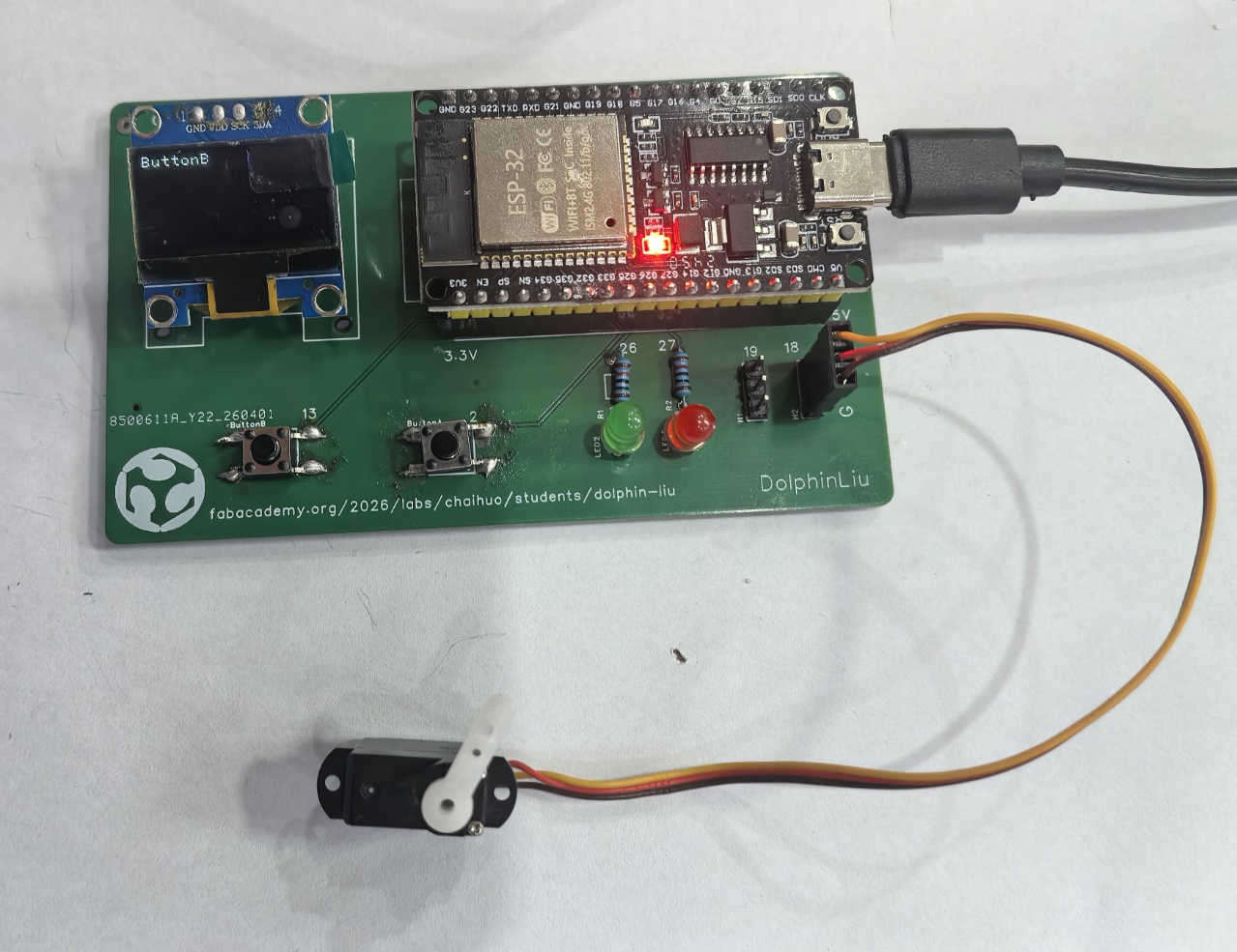
3.1.3 I connect Servo (3pin) to my PCB 3p pin header.
| Wire Color | Pin | Function |
|---|---|---|
| Black | G | Ground (GND / -) |
| Red | V | Power (VCC / +) |
| Yellow | S (GPIO18) | Signal (SIG / Data) |
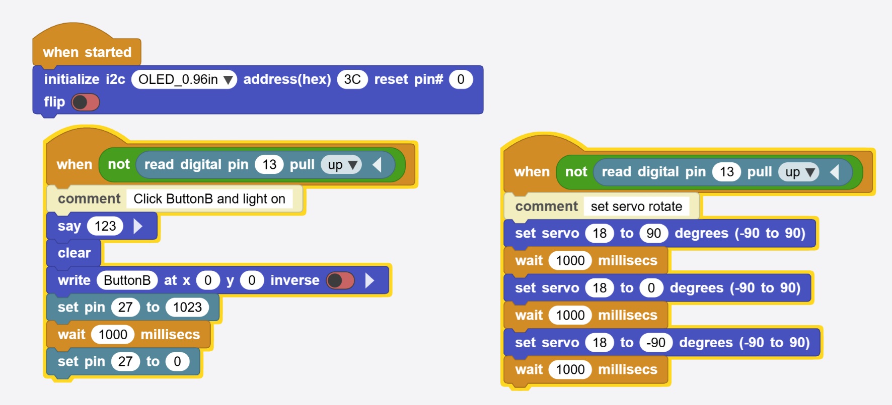
3.1.3 I write block code in MicroBlocks for quick testing :
I want to make the servo to rotate when I press the button.
 |  |
|---|
3.1.4 Here is the testing of servo :
3.2 Output Device - OLED Display
3.2.1 OLED Display
The 0.96-inch OLED Display is a compact, high-contrast monochrome screen widely used in embedded electronics and DIY projects. It features 128×64 pixels resolution and communicates via I2C or SPI interfaces, making it ideal for microcontrollers like Arduino and ESP32.
3.2.2 Working Principle
The 0.96" OLED operates on the principle of Electroluminescence. Unlike LCDs that require a backlight, OLED pixels emit their own light when an electric current passes through the organic layers.
-
Self-Emission: Each of the 128 × 64 pixels acts as an independent light source. This allows for "True Black" because pixels in dark areas are simply turned off.
-
Controller (SSD1306): This chip acts as the "brain," translating I2C/SPI commands into electrical signals that light up specific coordinates on the 128 × 64 grid.
-
Efficiency: Since only the active pixels consume power, it is highly efficient for displaying text and simple UI elements in battery-powered devices.
3.2.3 Here is my PCB pin connection with 0.96-inch OLED:
| OLED Pin | ESP32 Pin | Function |
|---|---|---|
| GND | GND | Ground |
| VCC | 5V | Power Supply |
| SCK | GPIO22 | I2C Clock Line (SCL) |
| SDA | GPIO21 | I2C Data Line (SDA) |
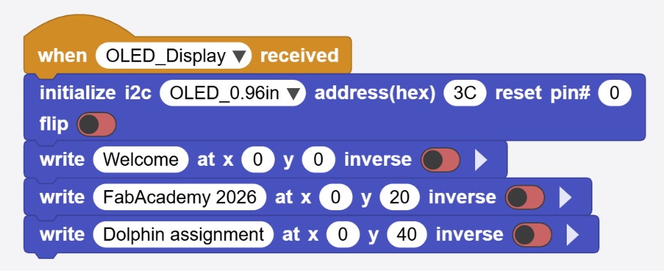
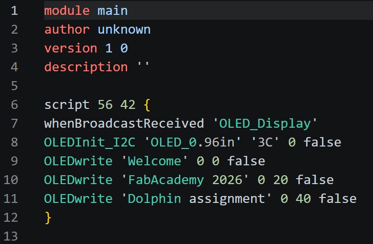
3.2.4 I write block code in MicroBlocks for quick testing :
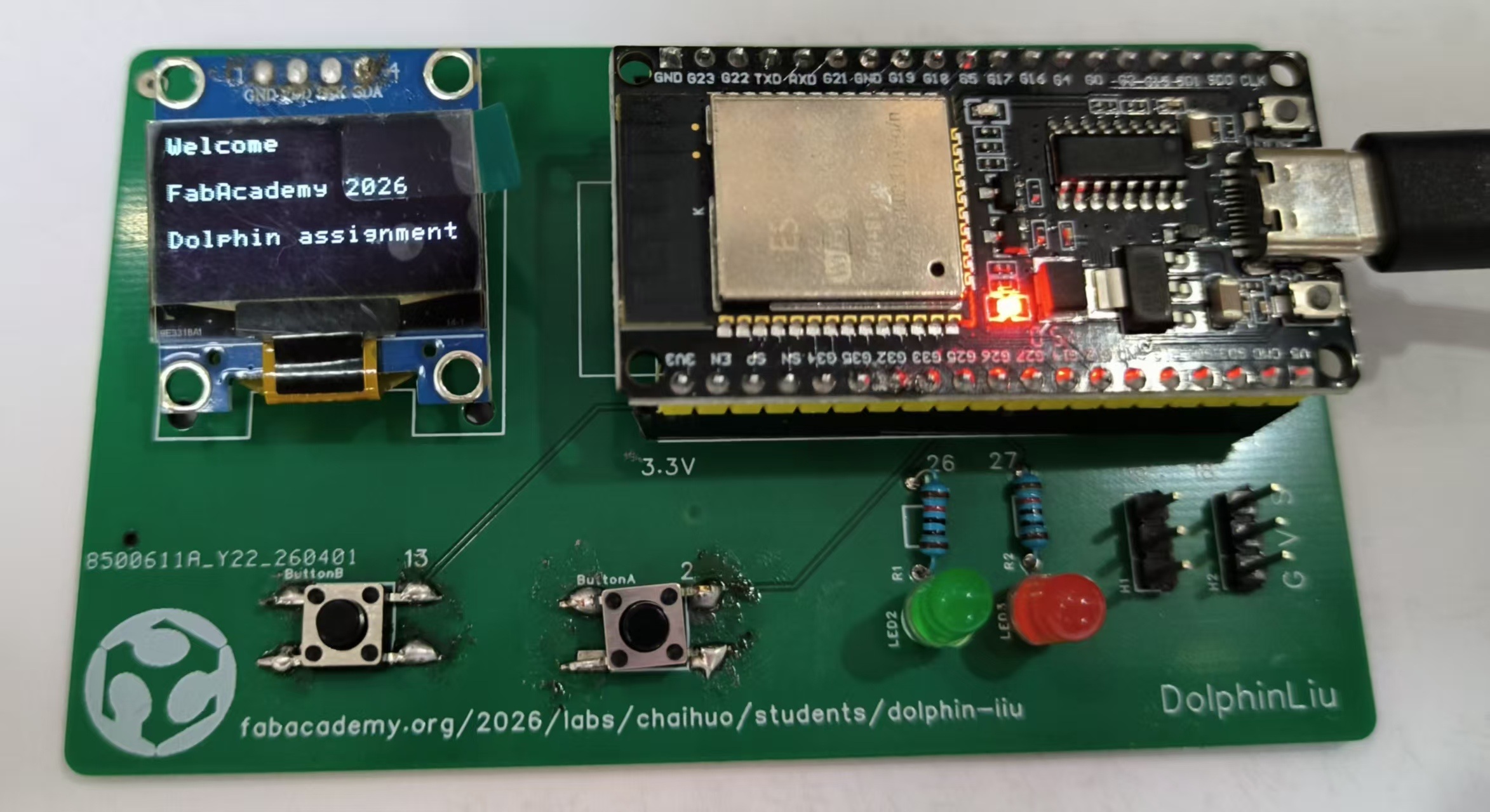
I want to show information on the OLED display - "Welcome FabAcademy 2026 Dolphin assignment"
 |  |
|---|
3.2.5 Here is the testing of OLED Display :
3.3 Output Device - 4Digital Display
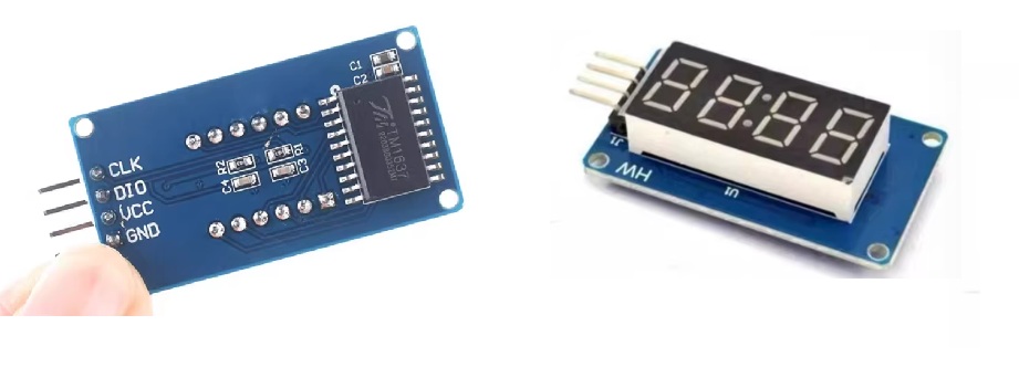
3.3.1 4-digital display
The TM1637 4-Digit Display is a compact and cost-effective LED display module featuring four 7-segment digits with a built-in colon for clock functionality. It integrates the TM1637 driver chip, which handles all scanning and decoding tasks, requiring only two GPIO pins (CLK and DIO) for communication via a proprietary serial protocol.
3.3.2 Working Principle
The TM1637 module communicates with the host controller via a 2-wire serial interface (CLK, DIO). Its core operating principles are as follows:
-
Auto-Scanning: The integrated dynamic scanning circuit sequentially drives each digit internally, maintaining stable 4-digit display without requiring continuous CPU refresh.
-
Pin Efficiency: Only 2 GPIO pins control up to 32 LED segments (4 digits × 8 segments), significantly reducing hardware resource usage compared to direct drive methods.
-
Internal Display RAM: Data sent to the chip is stored in built-in registers until the next update, minimizing communication overhead and bus traffic.
-
Programmable Brightness: 8-level brightness control via software commands, allowing adaptation to varying ambient lighting conditions.
3.3.3 Here is my PCB pin connection with 4-digital display:
| 4-Digital Display | ESP32 Pin | Function |
|---|---|---|
| GND | GND | Ground |
| VCC | 5V / 3.3V | Power Supply |
| DIO | GPIO19 | Data I/O (Serial Data) |
| CLK | GPIO18 | Clock Signal (Serial Clock) |
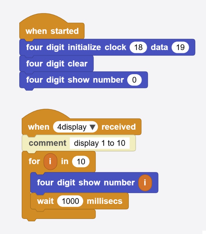
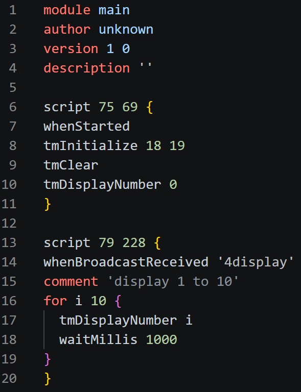
3.3.4 I write block code in MicroBlocks for quick testing :
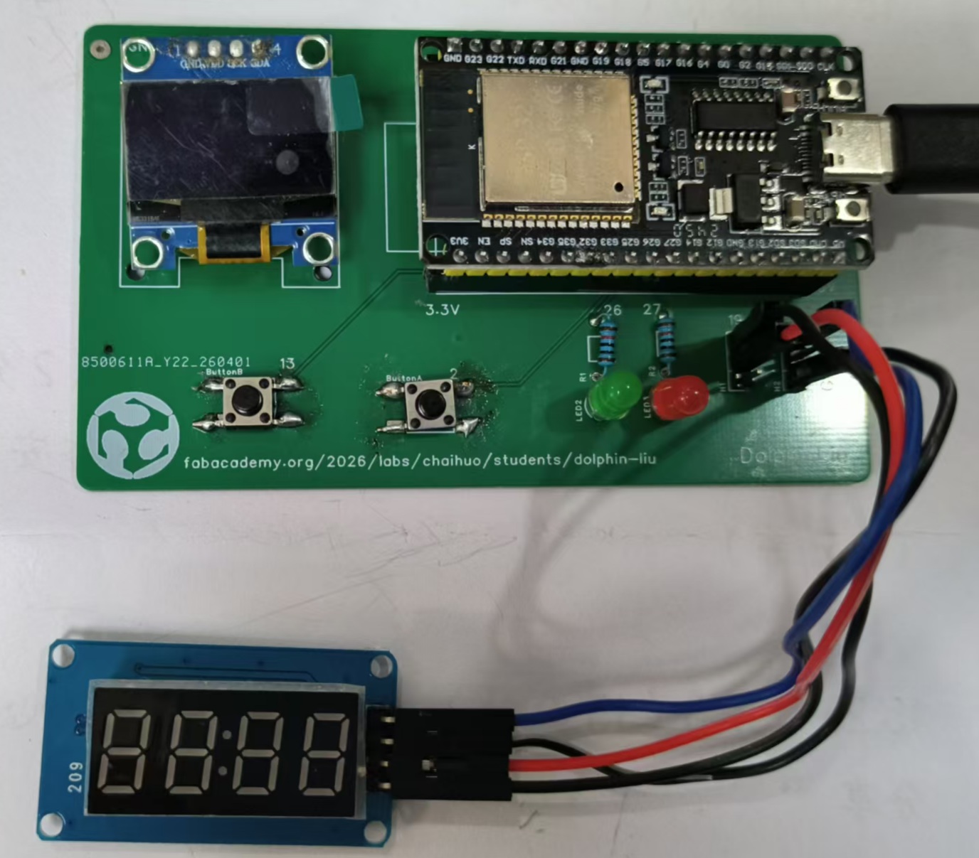
I want to show from 1 to 10 in 4-digital display.
 |  |
|---|
3.3.5 Here is the testing of 4-digital display :
3.4 Output Device - Active Buzzer Module
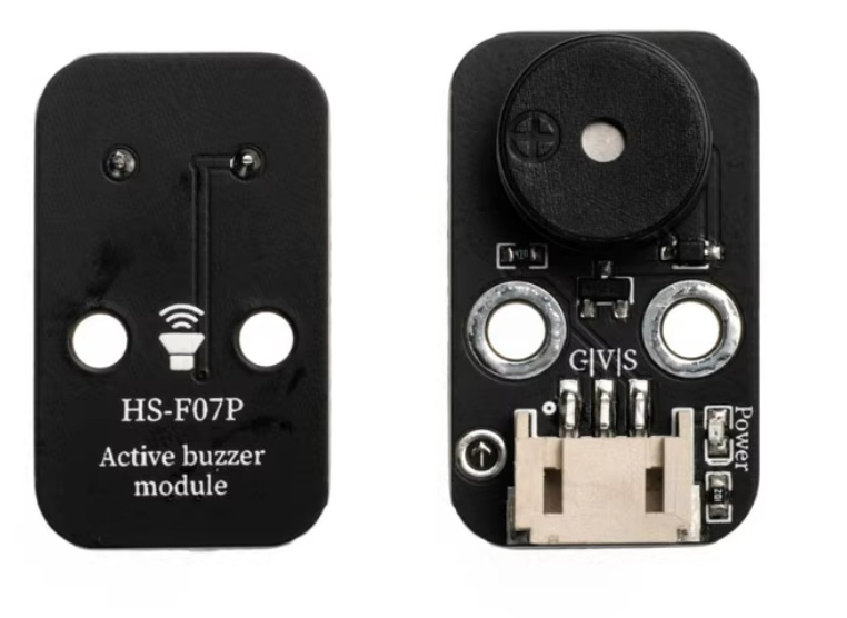
3.4.1 Active Buzzer Module
The Active Buzzer Module is a simple, self-contained audio output device that generates a fixed-tone sound when powered. Unlike passive buzzers, it includes a built-in oscillator circuit, requiring only a DC voltage (HIGH signal) to produce sound—no PWM or external frequency generation needed.
3.4.2 Working Principle
The Active Buzzer Module is designed for simplicity: DC voltage in → fixed sound out. Unlike a passive buzzer, it does not require a fluctuating signal (PWM) to produce tone.
Core Components Inside the Module
-
Electromagnetic Buzzer Element (diaphragm + coil)
-
Built-in Oscillator Circuit (transistor, resistor, capacitor — often potted in black epoxy)
-
Driver Transistor (on the module board, for current amplification)
-
Current-limiting Resistor (protects the control pin)
-
Three pins (usually: VCC, GND, I/O)
| Feature | Active Buzzer | Passive Buzzer |
|---|---|---|
| Needs PWM / variable frequency? | ❌ No | ✅ Yes |
| Needs DC voltage (HIGH signal)? | ✅ Yes | ❌ No (needs AC/square wave) |
| Built-in oscillator? | ✅ Yes | ❌ No |
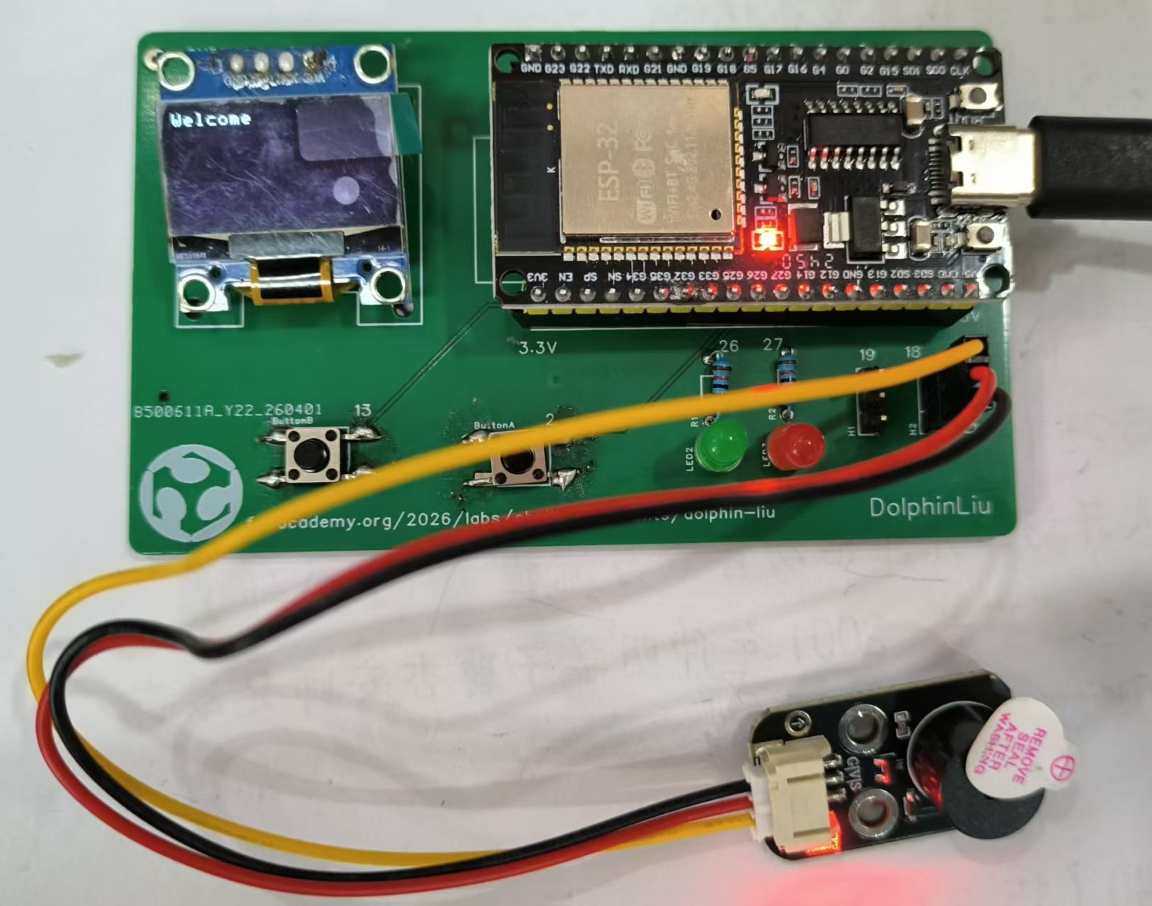
3.4.3 Connect Active Buzzer Module to my PCB 3p pin header.
| Buzzer Pin | ESP32 Pin | Function |
|---|---|---|
| GND | GND | Ground |
| VCC | 5V / 3.3V | Power Supply |
| I/O / S | GPIO19 | Signal Input (HIGH = ON, LOW = OFF) |
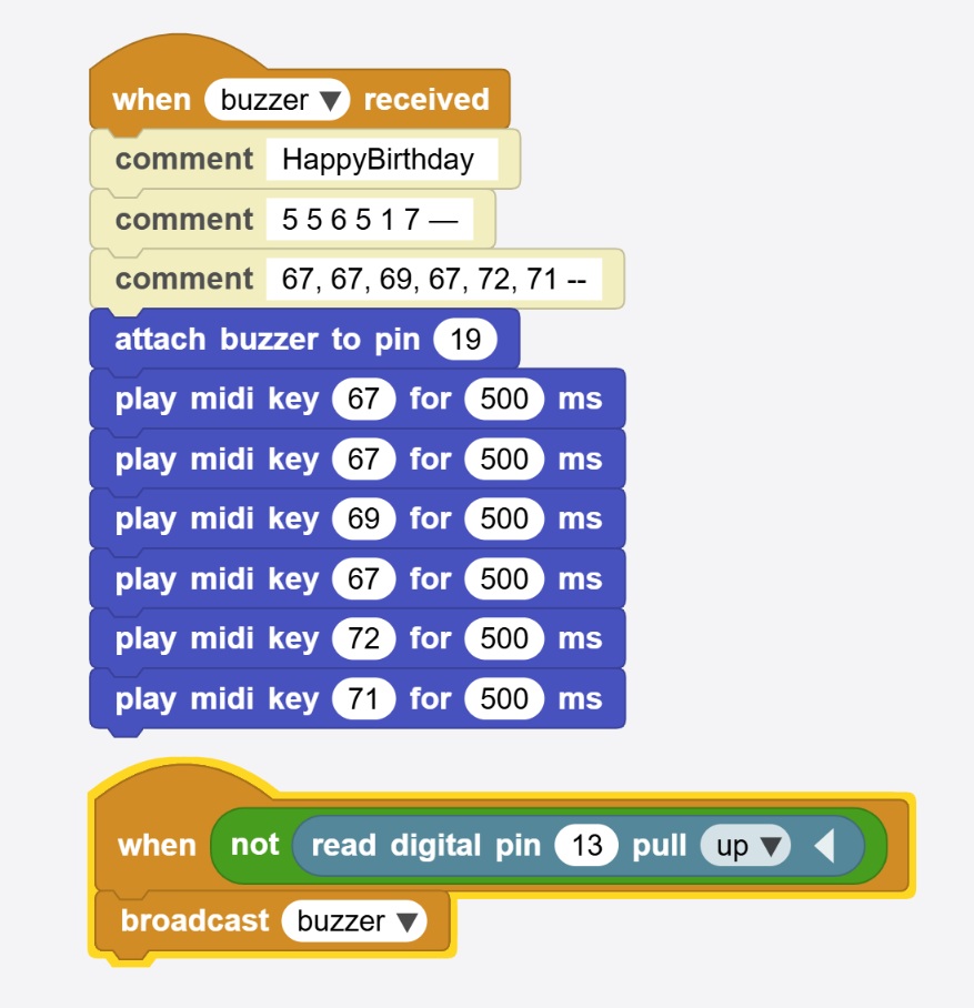
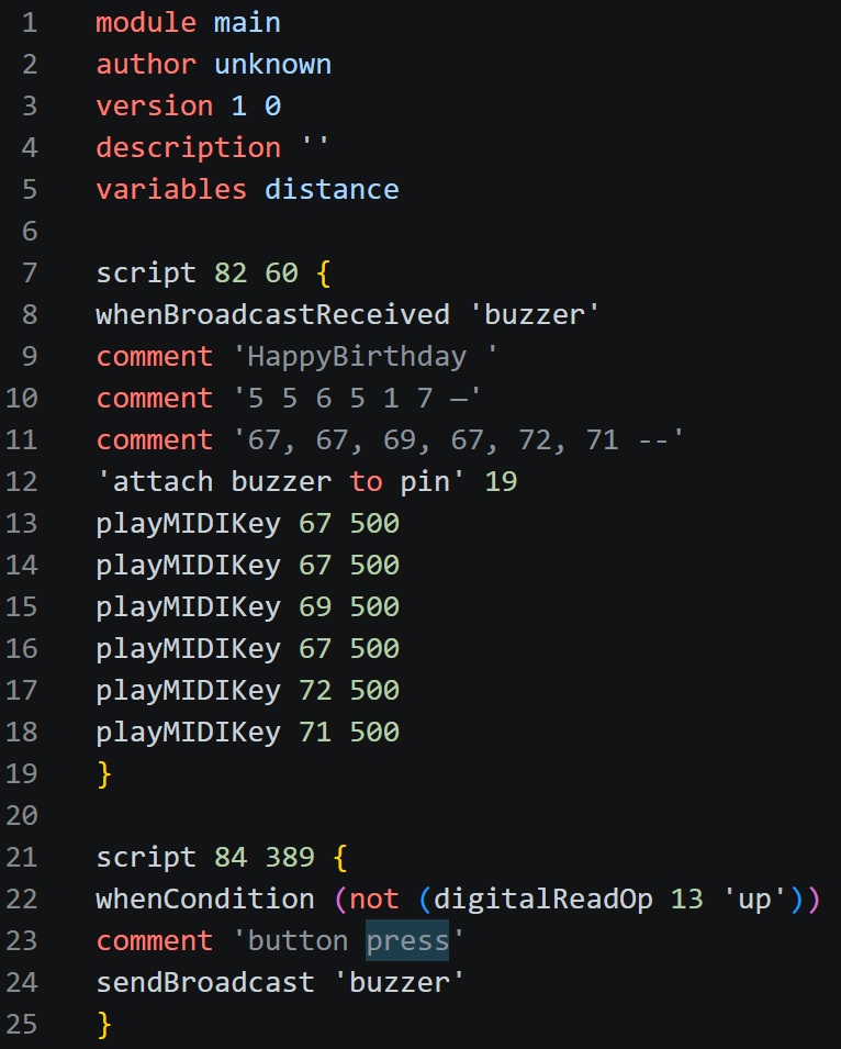
3.4.4 Coding
I write block code in MicroBlocks for quick testing :
I want to buzzer to play a song "happy birthday".
 |  |
|---|
3.4.5 Testing
Here is the testing of buzzer :