2. Output Devices
2.1. Grove device
I have some grove interface device, such as :rgb led, button,oled display,buzzer etc. I use ESP32Uno and Seed's Base Shield Grove extension board to connect them.
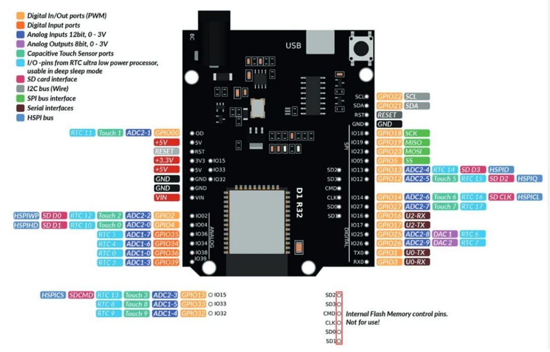
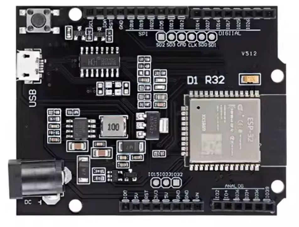
Here is the ESP32 Uno D1 pinout :
 |  |
|---|
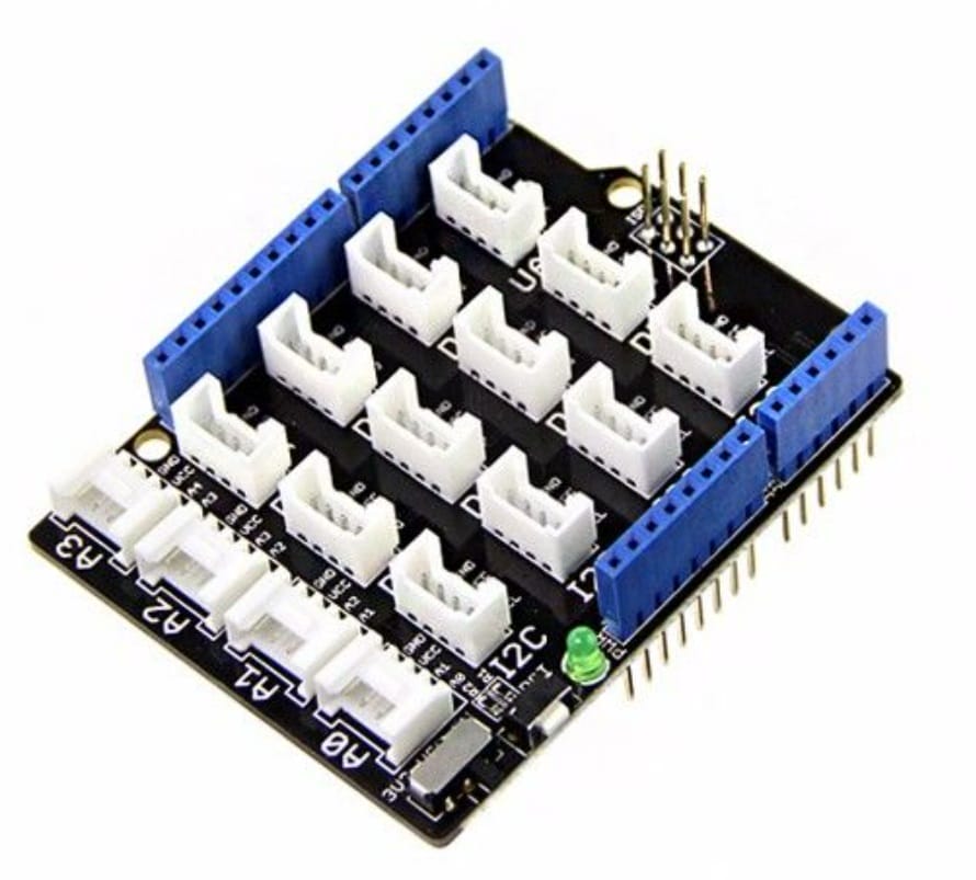
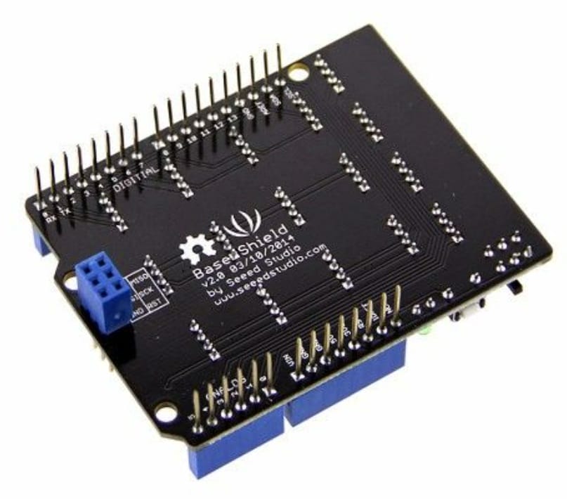
Here is the Base Shield Grove extension board:
 |  |
|---|
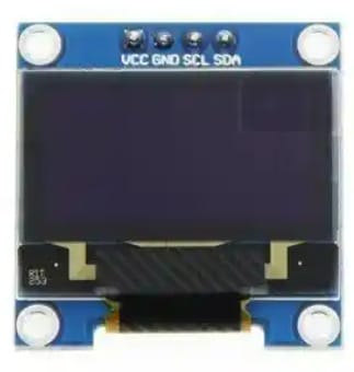
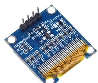
2.1.1 OLED Display 0.96
The Grove OLED Display 0.96" is a compact, high-contrast display module featuring 128×64 pixels for showing text, graphics, and simple animations in Grove-based projects.
| Pin | Function |
|---|---|
| GND | Ground |
| VCC | Power supply |
| SDA | I2C Data |
| SCL | I2C Clock |
 |  |
|---|
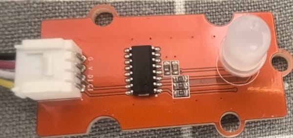
2.1.2 RGB LED
The Grove RGB LED is a full-color output module featuring a single LED capable of displaying millions of colors by mixing Red, Green, and Blue light.
| Pin | Function | Description |
|---|---|---|
| GND | Ground | Common ground reference |
| VCC | Power supply | 5V or 3.3V input |
| D1 | Data In | Digital signal input (I2C data or serial data stream) |
| C1 | Clock In | Clock signal for synchronous data transfer |
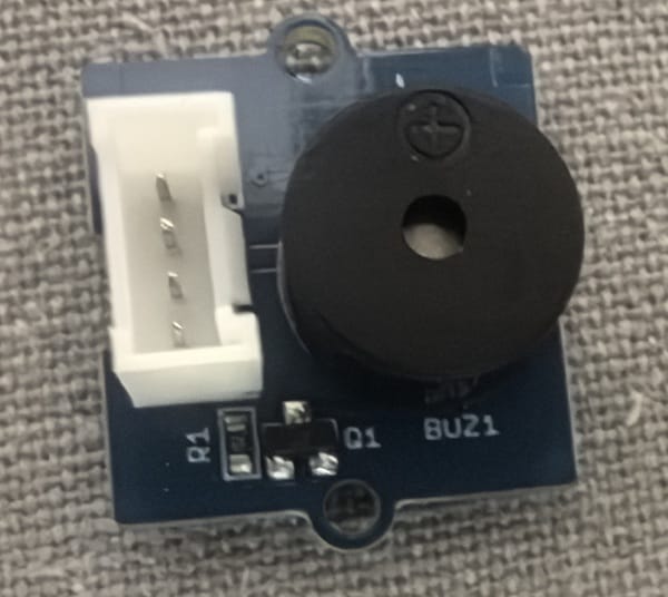
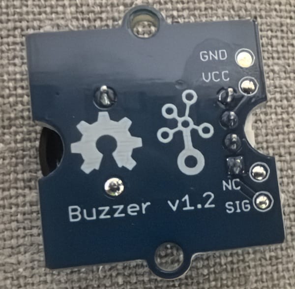
2.1.3 Buzzer
The Grove Buzzer is a simple audio output module that produces sound for alerts, notifications, or simple tones in Grove-based projects.
| Pin | Function |
|---|---|
| GND | Ground |
| VCC | Power supply |
| NC | Not connected |
| SIG | Control signal (Digital/PWM) |
 |  |
|---|
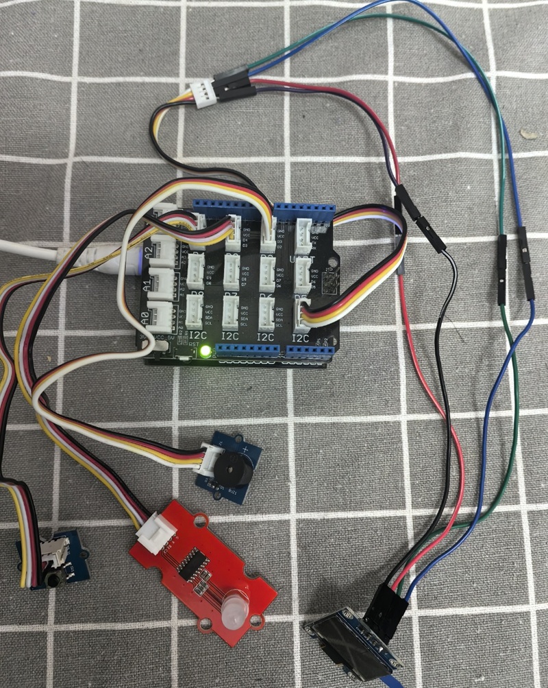
2.2 Connection Diagram
I connet Buzzer to D2 , RGB Led to D3, Button to D4,and OLED to I2C port. The ESP32 with Base Shield Connection Diagram :
2.3 coding
2.3.1 with MicroBlocks
2.3.1.1 Block Code in MicroBlocks
Here is the block code in MicroBlocks:
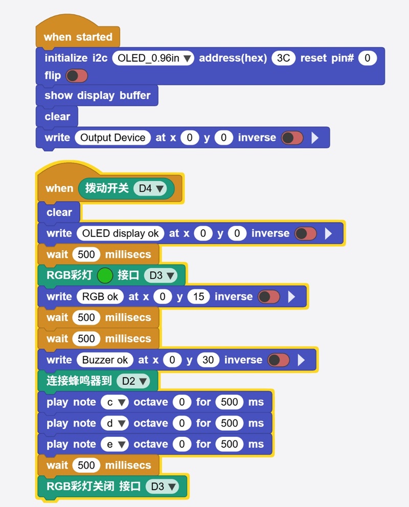
Here is the code of block code above:
script 107 52 {
whenStarted
OLEDInit_I2C 'OLED_0.96in' '3C' 0 false
OLEDshowGDBuffer
OLEDclear
OLEDwrite 'Output Device' 0 0 false
}

script 109 242 {
whenCondition ('拨动开关' 'D4')
OLEDclear
OLEDwrite 'OLED display ok' 0 0 false
waitMillis 500
RGB灯 (colorSwatch 35 190 30 255) 'D3'
OLEDwrite 'RGB ok' 0 15 false
waitMillis 500
waitMillis 500
OLEDwrite 'Buzzer ok' 0 30 false
'连接蜂鸣器' 'D2'
'play tone' 'nt;c' 0 500
'play tone' 'nt;d' 0 500
'play tone' 'nt;e' 0 500
waitMillis 500
'RGB灯关闭 端口 D' 'D3'
}
2.3.1.2 Run and Debug the program
Here is the video of block code program runing in MicroBlocks:
Here is the video of testing the buttons and rotary:
2.3.1.3 Source code
2.3.2 coding in VSCode+PlatformIO
Here is the platformio.ini file:
[env:esp32dev]
platform = espressif32
board = esp32dev
framework = arduino
lib_deps =
    adafruit/Adafruit SSD1306 @ ^2.5.7
    adafruit/Adafruit GFX Library @ ^1.11.5
Here is the main.cpp file:
#include <Arduino.h>
#include <Wire.h>
#include <Adafruit_GFX.h>
#include <Adafruit_SSD1306.h>

// 引脚定义
#define PIN_SWITCH  17  // D4 拨动开关
#define PIN_BUZZER  26  // D2 蜂鸣器
#define PIN_RGB_DAT 25  // D3 数据
#define PIN_RGB_CLK 16  // D3 对应的时钟 (基于源码 wr32_GPIO_D 处理)

// OLED 设置
#define SCREEN_WIDTH 128
#define SCREEN_HEIGHT 64
#define OLED_RESET    -1
Adafruit_SSD1306 display(SCREEN_WIDTH, SCREEN_HEIGHT, &Wire, OLED_RESET);

// 音符频率定义 (nt;c, nt;d, nt;e)
#define NOTE_C 262
#define NOTE_D 294
#define NOTE_E 330

// 模拟 MicroBlocks 的 RGB 灯关闭逻辑
void disableRGB() {
    pinMode(PIN_RGB_DAT, OUTPUT);
    pinMode(PIN_RGB_CLK, OUTPUT);
    digitalWrite(PIN_RGB_DAT, LOW);
    digitalWrite(PIN_RGB_CLK, LOW);
}

void setup() {
    Serial.begin(115200);

    // 初始化引脚
    pinMode(PIN_SWITCH, INPUT_PULLUP);
    pinMode(PIN_BUZZER, OUTPUT);

    // 初始化 OLED
    if(!display.begin(SSD1306_SWITCHCAPVCC, 0x3C)) {
        for(;;);
    }

    // Initial Display (whenStarted)
    display.clearDisplay();
    display.setTextSize(1);
    display.setTextColor(SSD1306_WHITE);
    display.setCursor(0, 0);
    display.print("Output Device");
    display.display();
}

void loop() {
    // 检查拨动开关 (whenCondition D4)
    // 注意:MicroBlocks 的拨动开关通常在按下/拨动时为 HIGH
    if (digitalRead(PIN_SWITCH) == LOW) { // 假设低电平触发,根据硬件可改 HIGH

        // 1. OLED display ok
        display.clearDisplay();
        display.setCursor(0, 0);
        display.print("OLED display ok");
        display.display();
        delay(500);

        // 2. RGB ok (这里简化为逻辑占位,因为 Minode 协议较特殊)
        display.setCursor(0, 15);
        display.print("RGB ok");
        display.display();
        // 模拟点亮 RGB (此处建议根据实际灯珠型号换用 FastLED 库)
        Serial.println("RGB LED On (D3)");
        delay(1000);

        // 3. Buzzer ok
        display.setCursor(0, 30);
        display.print("Buzzer ok");
        display.display();

        // 播放 C, D, E 音符 (每个 500ms)
        tone(PIN_BUZZER, NOTE_C, 500); delay(500);
        tone(PIN_BUZZER, NOTE_D, 500); delay(500);
        tone(PIN_BUZZER, NOTE_E, 500); delay(500);

        delay(500);

        // 4. 关闭 RGB
        disableRGB();
        Serial.println("RGB LED Off");

        // 等待开关松开,防止重复触发
        while(digitalRead(PIN_SWITCH) == LOW);
    }
}
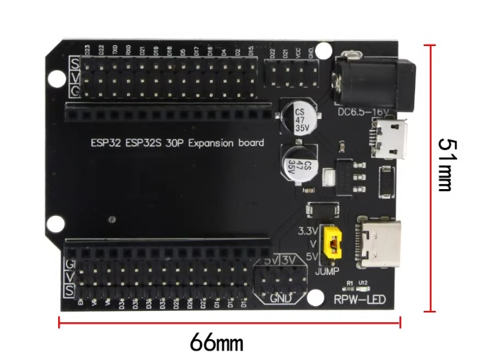
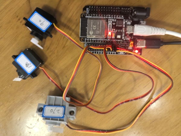
2.4 Servo device
I have some Servo device,such as: 90° Servo, 180° Servo,270° Servo. I use ESP32 dev kit and the common extension board to connect the servo devices.
2.4.1 90° Servo
The 90° servo offers quarter-turn rotation (0°–90°) for compact, precise applications like grippers and triggers.
2.4.2 180° Servo
The 180° servo is the standard half-turn (0°–180°) servo for general use in robot arms, camera mounts, and steering.
2.4.3 270° Servo
The 270° servo provides extended three-quarter turn (0°–270°) for wide-coverage applications like surveillance systems.
2.5 Connection Diagram
The Servo has 3 pin . G (Ground) is the common ground, V (Voltage) accepts 3.3V–5V power, and S (Signal) receives PWM pulses to set the angle.
Here is the ESP32 dev kit and the common extension board:
 |  |
|---|
2.6 coding
2.6.1 code in MicroBlocks
Here is the block code in MicroBlocks:
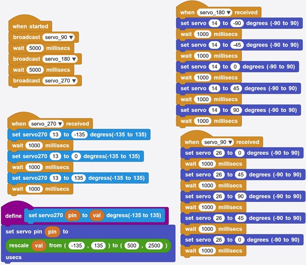
Here is the source code of block code above:
  spec ' ' 'servo270' 'set servo270 _ to _ degress(-135 to 135)' 'auto auto' '10' '10'

to servo270 pin val {
  '[io:setServo]' pin ('[misc:rescale]' val -135 135 500 2500)
}


script 58 74 {
whenStarted
sendBroadcast 'servo_90'
waitMillis 5000
sendBroadcast 'servo_180'
waitMillis 5000
sendBroadcast 'servo_270'
}

script 474 40 {
whenBroadcastReceived 'servo_180'
setServoAngle 14 -90
waitMillis 1000
setServoAngle 14 -45
waitMillis 1000
setServoAngle 14 0
waitMillis 1000
setServoAngle 14 45
waitMillis 1000
setServoAngle 14 90
waitMillis 1000
}


script 56 316 {
whenBroadcastReceived 'servo_270'
servo270 13 -135
waitMillis 1000
servo270 13 0
waitMillis 1000
servo270 13 135
waitMillis 1000
}

script 485 362 {
whenBroadcastReceived 'servo_90'
setServoAngle 26 0
waitMillis 1000
setServoAngle 26 45
waitMillis 1000
setServoAngle 26 90
waitMillis 1000
setServoAngle 26 45
waitMillis 1000
setServoAngle 26 0
waitMillis 1000
}
2.6.2. Run the program
Here is the video of block code program runing in MicroBlocks:
2.6.3 Source code
2.6.4 coding with VSCode+PlatformIO
2.4 coding with VSCode+PlatformIO
Here is the platformio.ini file:
[env:esp32dev]
platform = espressif32
board = esp32dev
framework = arduino
lib_deps =
    madhephaestus/ESP32Servo @ ^1.1.0
Here is the main.cpp file:
#include <Arduino.h>
#include <ESP32Servo.h>

// 定义引脚
const int PIN_SERVO_90  = 26;
const int PIN_SERVO_180 = 14;
const int PIN_SERVO_270 = 13;

// 创建舵机对象
Servo servo90;
Servo servo180;
Servo servo270;

// 模拟 MicroBlocks 中的 setServoAngle (-90 到 90 度)
// 根据 MicroBlocks 源码: pulseWidth = 1500 - (10 * degrees)
void setServoAngle(Servo &s, int degrees) {
    int pulseWidth = 1500 - (10 * degrees);
    s.writeMicroseconds(pulseWidth);
}

// 模拟 MicroBlocks 中的 servo270 (-135 到 135 度)
// 根据源码: rescale val -135 135 500 2500
void setServo270(Servo &s, int val) {
    int pulseWidth = map(val, -135, 135, 500, 2500);
    s.writeMicroseconds(pulseWidth);
}

void setup() {
    Serial.begin(115200);

    // 分配硬件定时器资源 (ESP32Servo 特有)
    ESP32PWM::allocateTimer(0);
    ESP32PWM::allocateTimer(1);
    ESP32PWM::allocateTimer(2);
    ESP32PWM::allocateTimer(3);

    // 初始化舵机,设置标准脉宽范围 (500us - 2500us)
    servo90.setPeriodHertz(50);
    servo180.setPeriodHertz(50);
    servo270.setPeriodHertz(50);

    servo90.attach(PIN_SERVO_90, 500, 2500);
    servo180.attach(PIN_SERVO_180, 500, 2500);
    servo270.attach(PIN_SERVO_270, 500, 2500);

    Serial.println("Servos Initialized.");
}

void loop() {
    // --- 任务 1: 90度舵机逻辑 (servo_90) ---
    Serial.println("Task: Servo 90");
    setServoAngle(servo90, 0);   delay(1000);
    setServoAngle(servo90, 45);  delay(1000);
    setServoAngle(servo90, 90);  delay(1000);
    setServoAngle(servo90, 45);  delay(1000);
    setServoAngle(servo90, 0);   delay(1000);

    delay(5000); // 对应 MicroBlocks 中间的等待

    // --- 任务 2: 180度舵机逻辑 (servo_180) ---
    Serial.println("Task: Servo 180");
    setServoAngle(servo180, -90); delay(1000);
    setServoAngle(servo180, -45); delay(1000);
    setServoAngle(servo180, 0);   delay(1000);
    setServoAngle(servo180, 45);  delay(1000);
    setServoAngle(servo180, 90);  delay(1000);

    delay(5000);

    // --- 任务 3: 270度舵机逻辑 (servo_270) ---
    Serial.println("Task: Servo 270");
    setServo270(servo270, -135); delay(1000);
    setServo270(servo270, 0);    delay(1000);
    setServo270(servo270, 135);  delay(1000);

    // 程序运行一次后停止,或根据需要循环
    Serial.println("All sequences finished.");
    while(1) { delay(1000); }
}