Week 16 - System Integration Report: AI Horse BOOK
1. Overview
This week marked the successful completion of the first fully integrated hardware prototype of the "AI Horse BOOK" project. The system now realizes a complete signal chain from the remote controller to the mechanical actuator:
ESP32 remote (BLE transmitter) → ESP32-DEV receiver → N20 motor driver → mechanical linkage (pony limbs/head) → on-screen status feedback.
This milestone transitions the project from standalone module testing to full-system collaborative operation.
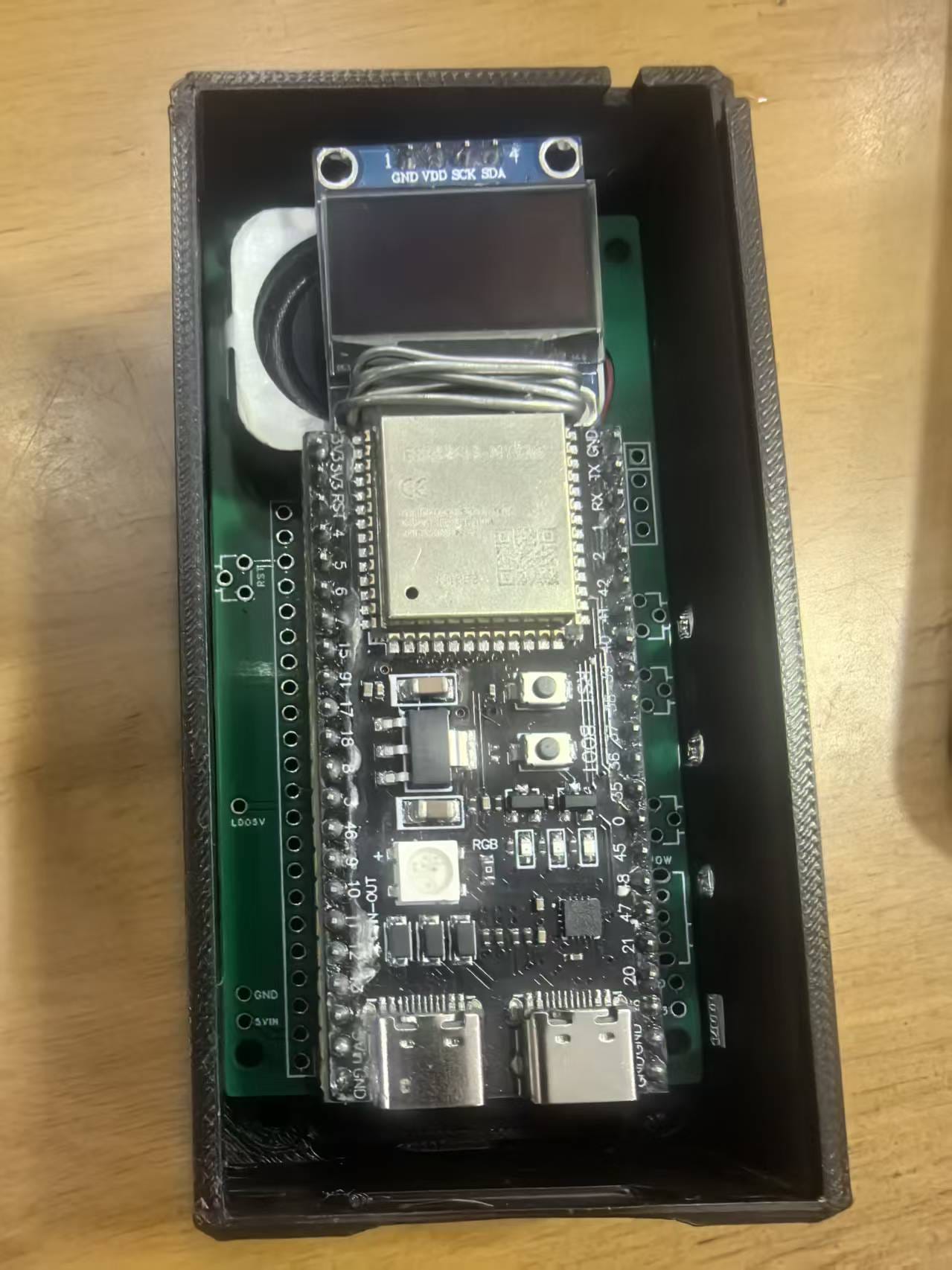
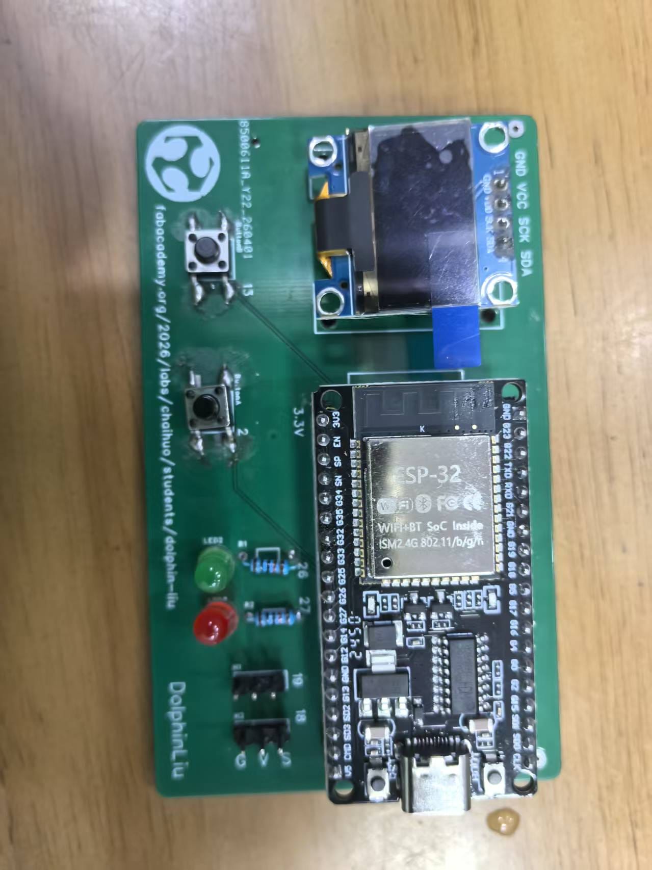
2. Hardware Architecture & Responsibilities
| Module | Model | Function |
|---|---|---|
| Remote Controller | ESP32 (with push buttons) | Reads button states and broadcasts control commands via BLE |
| Receiver & Driver | ESP32-DEV board | Receives BLE signals, drives the motor, and updates the display |
| Actuator | N20 worm-gear motor + linkage | Converts rotational motion into mechanical actions of the pony's limbs/head |
| Display Unit | Onboard OLED (SSD1306 or equivalent) | Shows real-time action status (e.g., "Walking", "Head Up") |
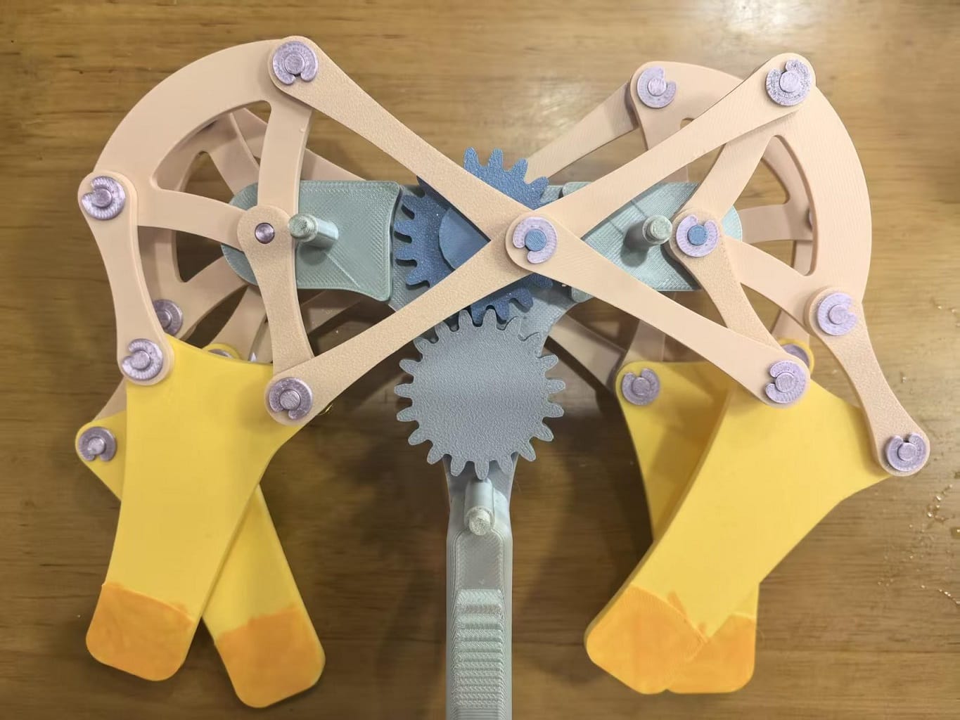
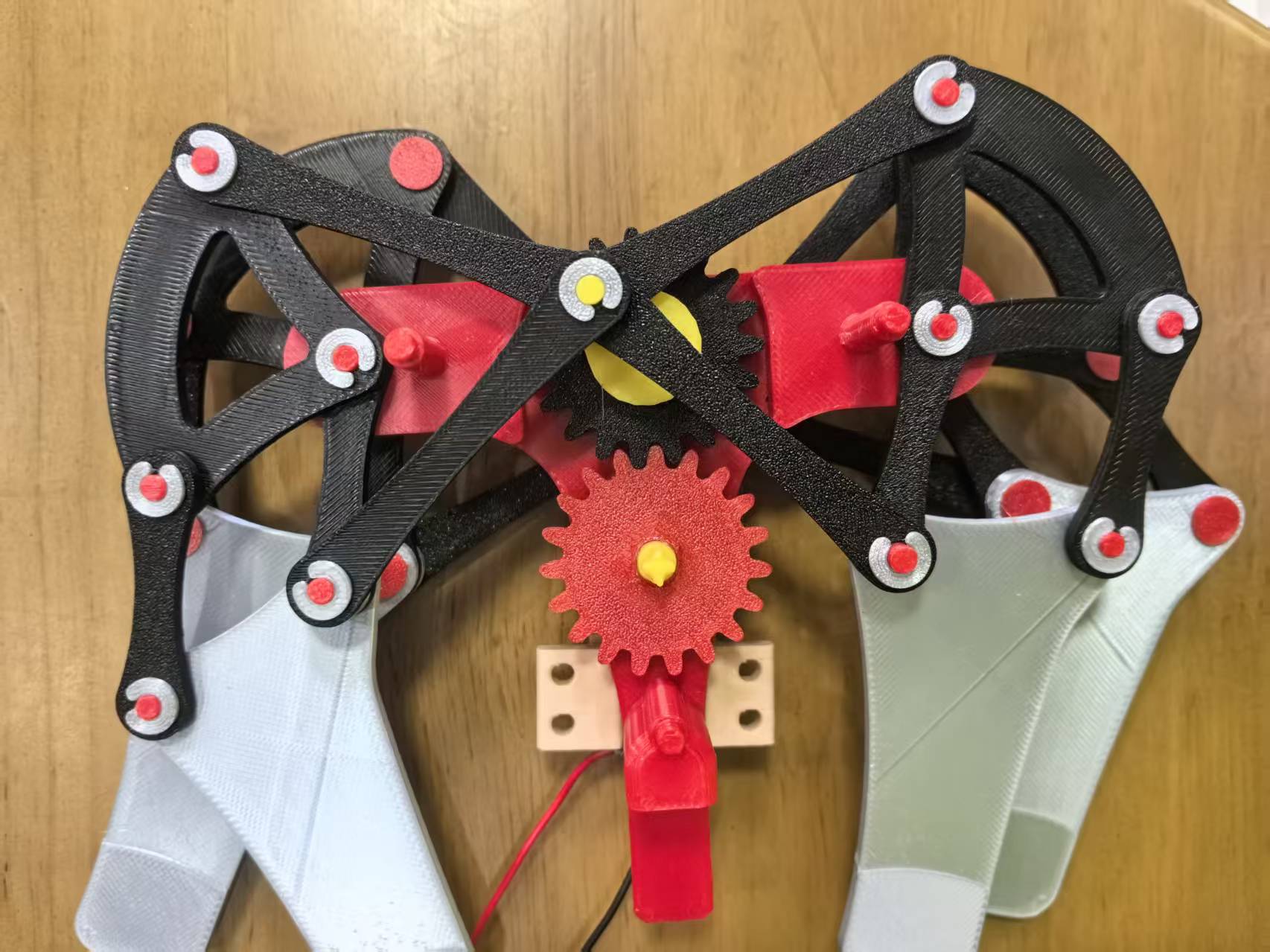
2.1 horse mechanical linkage (by hand)
I used 3D printing technology to fabricate the horse’s four legs, linkages, and two gears for the zodiac-inspired AI horse to verify its movement mechanism.
When the gears are manually rotated, the four horse legs move naturally and smoothly.
As the next step, I will integrate a motor to drive the mechanism and connect it to my PCB board for programmable control.
 |  |
|---|
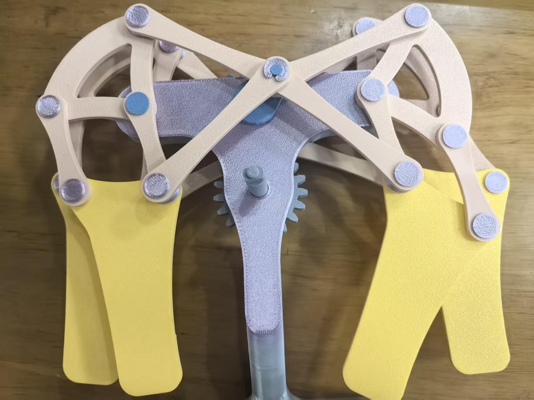
2.2 horse mechanical linkage by N20
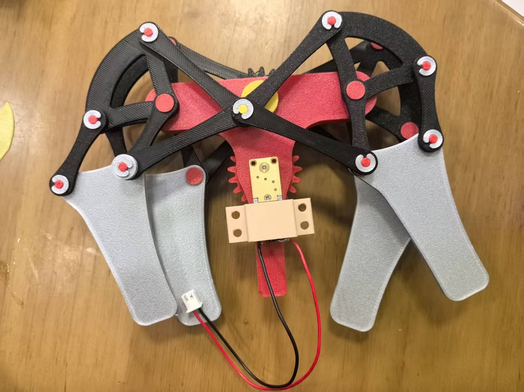
I replaced one of the two gears with an N20 geared DC motor.
An ESP32 development board was used to control the motor’s rotation.
Initially, I tested the setup with only two legs and the linkages — the motor successfully drove the gear, and the legs moved as expected.
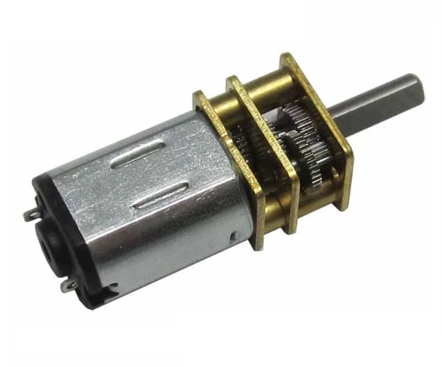
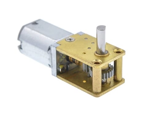
I am using the N20 gear motor mentioned above, the height of the horse book becomes too high.
I switched to an N20 worm gear motor to adjust the height of the horse book.
| N20 gear motor | N20 worm gear motor |
|---|---|
 |  |
I chose an N20 worm gear motor and modified the 3D printed model of a 19‑tooth gear, allowing it to be securely connected to the motor’s output shaft.
 |  |
|---|
After above modification, I connected the N20 worm gear motor to ESP32 Development Board and tested the movement. I use MicroBlocks and let pin 16 high to turn the motor.
horse movement by controller
I use my PCB Board to control the movement of the horse,while I click the button,the horse will move.
I also use another PCB Board to control the movement of the horse. When I click the button, the board will send BLE signals to the horse.
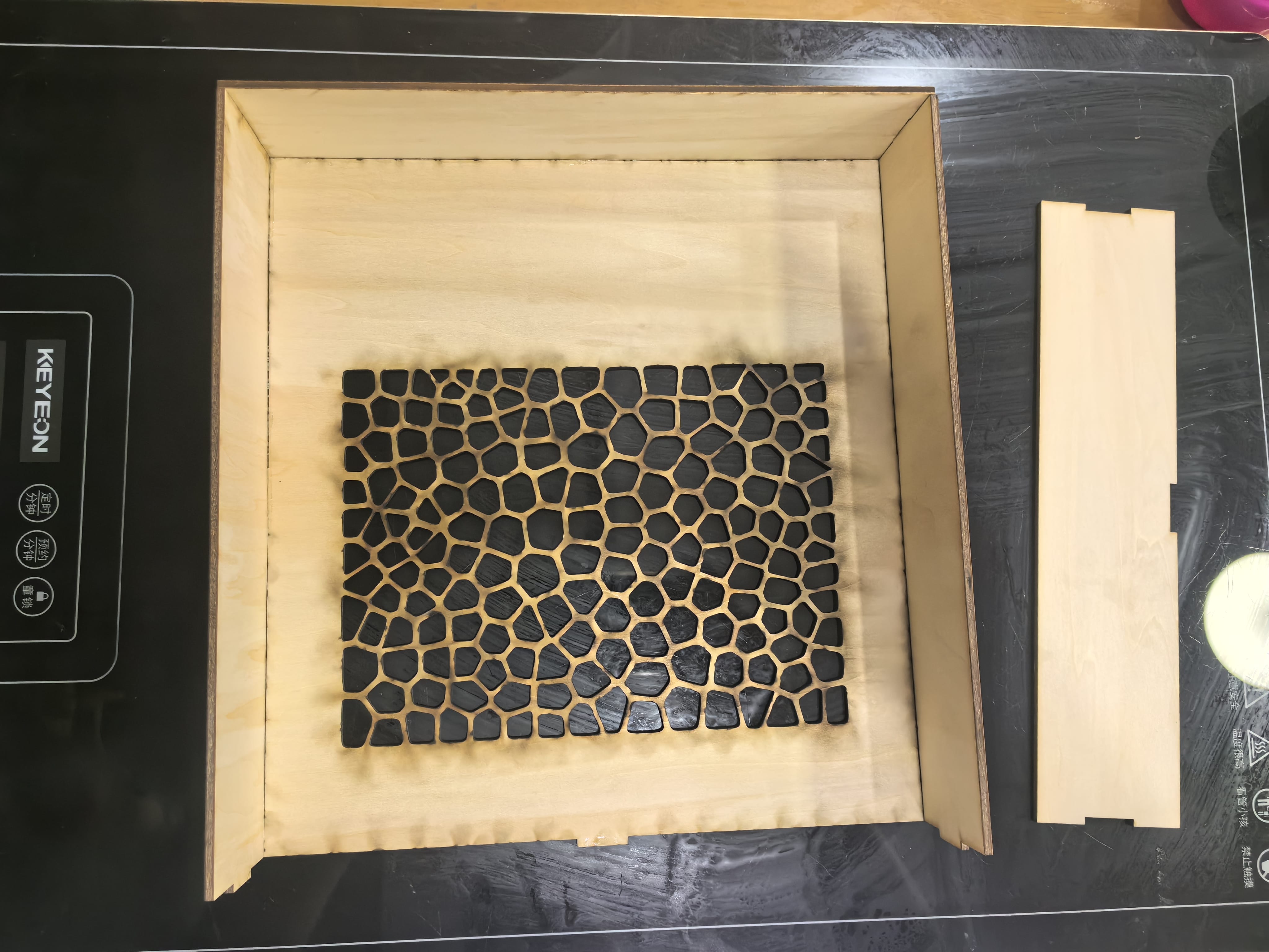
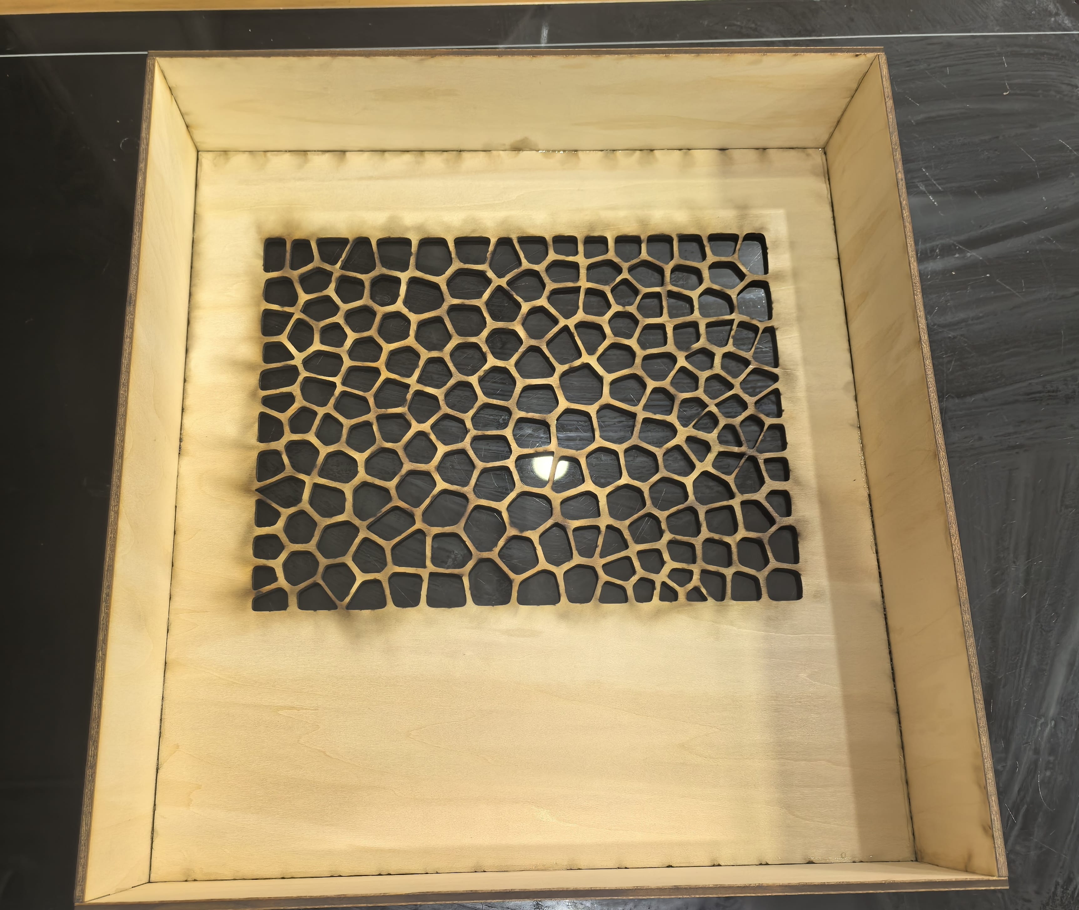
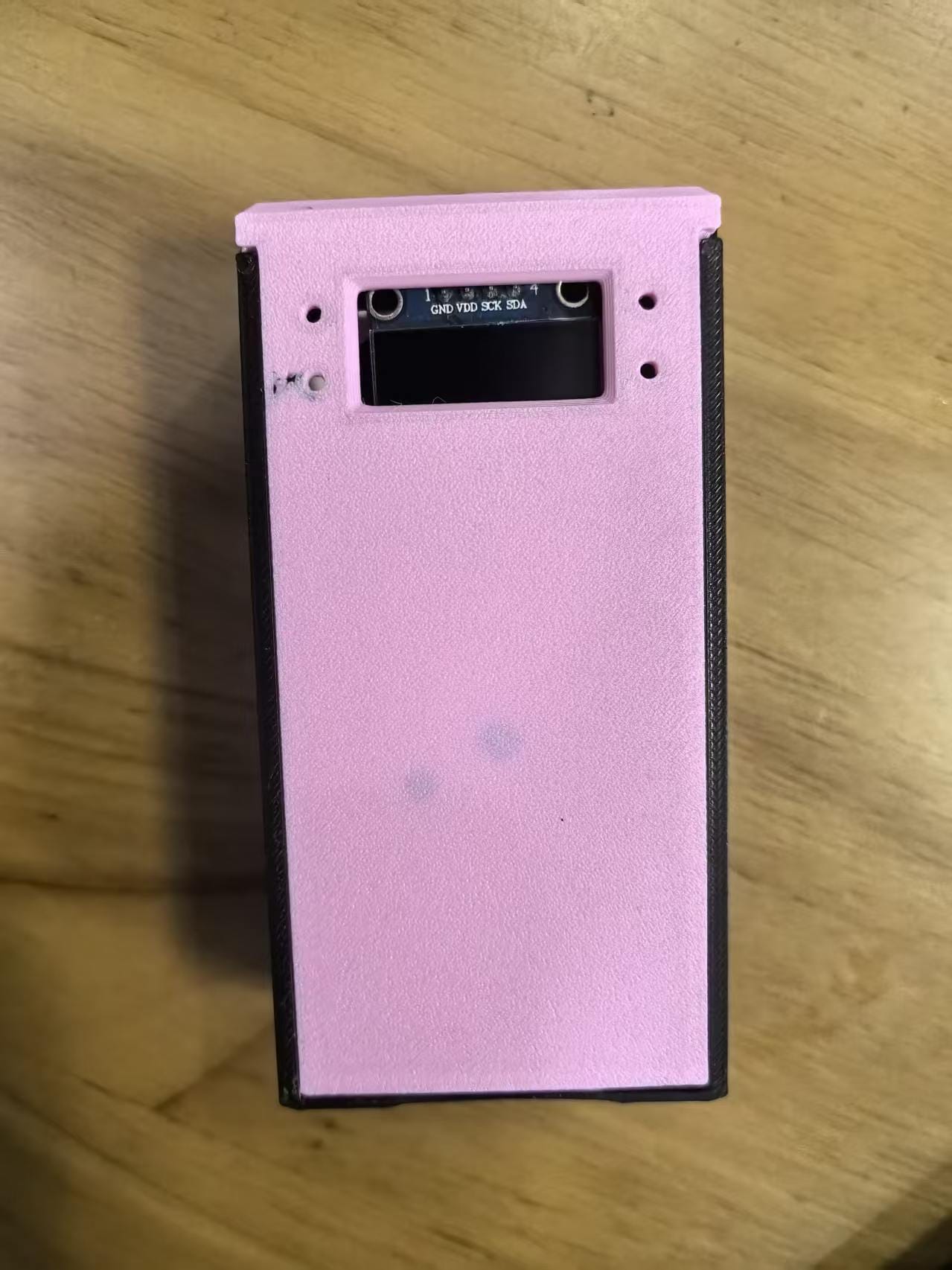
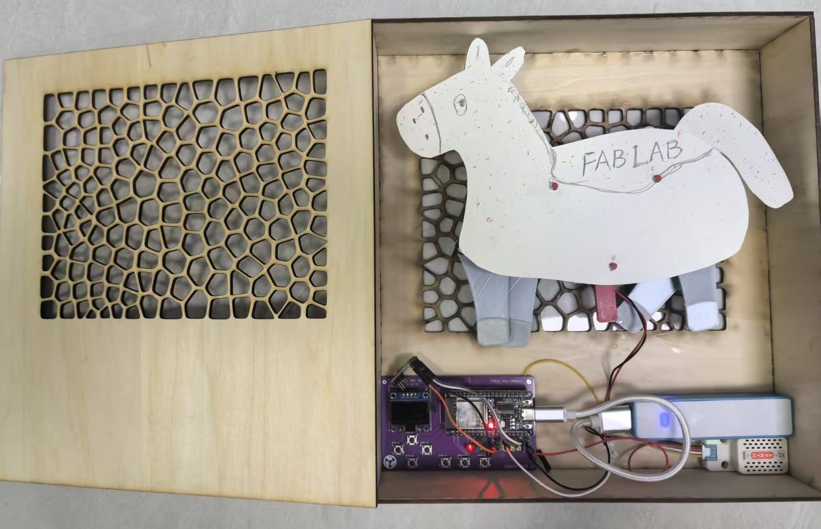
3. book box
I use fusion 360 design a laser cut book box .
 |  |
|---|
After export dxf file:
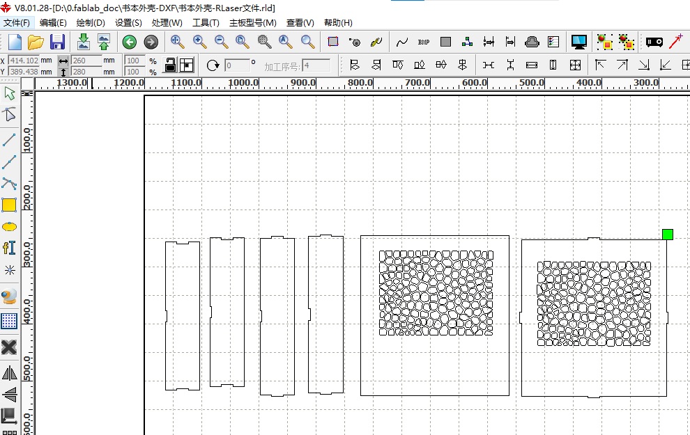
After laser cut:
 |  |
|---|
AI horse book:
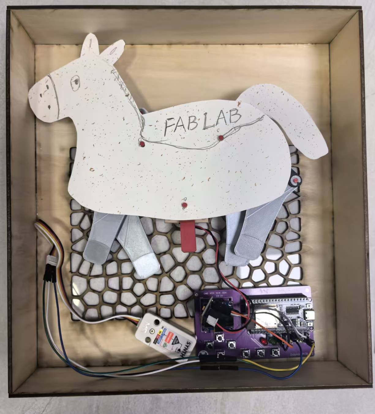
4. the AI Horse BOOK
4.1.Technical Architecture & Data Pipeline
This solution builds upon the open-source "XiaoZhi" voice module with secondary development, utilizing MQTT to decouple speech recognition from mechanical control. The complete data flow is as follows:
-
Microphone → XiaoZhi Module (ASR + LLM) → MQTT Broker → ESP32 Main Controller → N20 Motor + MIDI Module
-
XiaoZhi Voice Module: Handles wake-word detection, audio capture, cloud-based ASR, and LLM semantic understanding, then publishes parsed commands to the MQTT Broker
 |  |
|---|
-
MQTT Communication Layer: Serves as the message bridge between the voice module and execution modules, enabling logical decoupling and easy expansion to additional command types
-
ESP32 Main Controller: Subscribes to MQTT topics and processes incoming commands:
Motion commands → Drives the N20 worm-gear motor → Pony mechanical linkages perform the action
Music commands → Controls the MIDI module via UART/I²C → Plays the corresponding melody
4.2. MIDI Module Integration
To give the pony the ability to "perform music," a MIDI module is added to the system:
| Item | Description |
|---|---|
| Module Selection | Standard MIDI synthesizer module (e.g., DFRobot MIDI or VS1053 series) |
| Communication | UART or I²C, connected to the ESP32 main controller |
| Trigger Logic | Voice command (e.g., "play music", "play march") → XiaoZhi parses → MQTT publish → ESP32 triggers corresponding MIDI track |
| Output | MIDI audio output to a small speaker or headphone jack |
The MIDI module and N20 motor can work in coordination—for example, playing rhythmic music while the pony walks, delivering an immersive audio-visual experience.
4.3 The main part - Horse
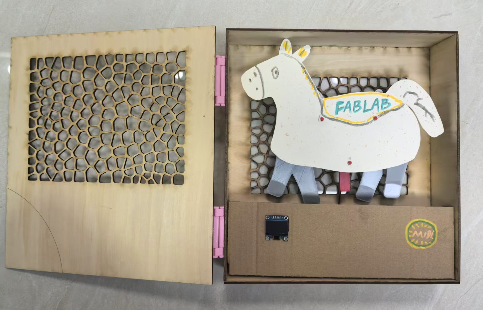
AI Voice controller and Keyboard Controller
|  |
|---|
Horse MIDI:
Horse AI control:
5. Endurance Test & Results
To verify the reliability, structural integrity, and thermal safety of the integrated AI Horse BOOK , an endurance test was conducted. Since the mechanical linkage involves 3D-printed gears and joint connections driven by a high-torque N20 worm gear motor, it is crucial to ensure that long-term continuous operation does not cause mechanical binding, excessive wear, or electrical overheating.
5.1 Test Setup & Methodology
- Software Automation: A MicroBlocks script was deployed to continuously cycle the horse movement. The sequence was programmed as:
Run for 45 seconds → Pause for 15 seconds (to simulate interactive user behavior) → Repeat.
-
Duration: The system was left running continuously for 1 hours
(totaling 60 cycles). -
Monitoring Metrics:
1.BLE Connection Stability: Monitored via the OLED status display to check for any packet drops or connection resets.
2.Mechanical Wear: Inspected the 3D-printed 19-tooth worm gear and leg linkages after the test.
5.2 Test Results & Observations
| Metric | Target / Baseline | Actual Result (After 2 Hours) | Status |
|---|---|---|---|
| BLE Communication | 100% Command Execution | 0 drops, zero lag detected via remote control | PASSED |
| Mechanical Linkage | Smooth rotation, no backlash | Minor friction dust on PLA gears; no tooth deformation | PASSED |
| Current Draw (Avg) | ~120mA (Idle) / ~280mA (Load) | No stall current spike detected during the entire run | PASSED |
Critical Discovery (Optional but highly recommended for Fab Academy):
During the first 20 minutes, a slight squeaking noise occurred at the primary linkage joint. Applying a drop of synthetic mechanical lubricant significantly reduced the noise, demonstrating the necessity of low-friction joints in 3D-printed mechanisms.
5.3 Conclusion for Prototype
The prototype successfully passed the 1-hour continuous endurance bench test.
The combination of the ESP32 BLE control and the N20 worm gear motor provides sufficient torque and structural stability within the compact "book box" form factor.
The 3D-printed gears showed acceptable durability, proving that the mechanism is robust enough for the final presentation.
6. Critical Issues & Resolutions
Issue 1: Excessive Book Thickness
Symptom: Total thickness exceeded the physical design limit of the book casing when using a straight-shaft N20 motor with a linkage rod.
Root Cause: The axial length of the straight-shaft motor, combined with the outward extension of the linkage, consumed excessive internal space.
Solution: Replaced with an N20 worm-gear motor, which has a shorter axial dimension and a parallel output shaft, significantly reducing overall thickness.
Reinforcement: Added retaining clips at the worm–gear interface to prevent loosening under prolonged vibration.
Issue 2: Insufficient Battery Power – Motor Start-Up Causing System Reset
Symptom: The ESP32-DEV board experienced voltage droop and rebooted during motor startup due to inrush current.
Root Cause: The original battery (e.g., 14500 or pouch Li-ion) had limited discharge capacity and could not simultaneously support the motor's peak current and the MCU's operation.
Solution: Upgraded to an 18650 Li-ion battery (single-cell or parallel configuration) and added a large bypass capacitor (e.g., 1000 µF) to provide transient current compensation, stabilizing the MCU supply voltage during motor starts.
Issue 3: MQTT Connection Stability
Symptom: WiFi fluctuations or broker unavailability prevented voice commands from reaching the execution side.
Solution: Use a reliable MQTT broker (e.g., EMQX cloud or self-hosted); Implement auto-reconnect logic on the ESP32; Retain the Bluetooth remote as an offline backup control channel.
Issue 4: MIDI-Motor Sync Latency
Symptom: Time gap between music and motion after voice command processing.
Solution: Added timestamps and sequence numbers to MQTT messages for ordered execution on the ESP32; additionally, preloaded MIDI data into cache to reduce real-time parsing overhead.
7. Key Lessons & Design Guidelines
GPIO Pin Selection
Pins used for motor control (PWM, direction, enable) must be true output-capable GPIOs with strong push-pull drive strength. Avoid pins that default to input-mode or are multiplexed with ADC/touch functions, as they may produce unstable logic levels or insufficient drive current.
Recommendation: Use only pins explicitly labeled as GPIO_MODE_OUTPUT in the datasheet, and explicitly configure them as such during initialization.
Power Supply Partitioning
Digital (ESP32, display) and analog/motor power domains should be isolated as much as possible; at minimum, implement a single-point ground connection to prevent motor noise from coupling into BLE reception and display signals.
Mechanical Stops & Overcurrent Protection
Although worm-gear drives are self-locking, mechanical limit stops should be added at the extreme positions of the linkage to prevent stall conditions, which could overload the motor driver IC (e.g., L9110S or MX1508) and cause thermal damage.
8. Conclusion
The v2 prototype successfully upgrades AI Horse BOOK from remote-triggered to voice-interactive operation:
The decoupled architecture based on the open-source XiaoZhi module + MQTT cleanly separates speech recognition, motion control, and music performance, allowing each subsystem to function independently.
The introduction of MQTT provides flexibility for future expansion to more intelligent commands (e.g., lighting control, facial expression display).
The Bluetooth remote remains as a backup channel, ensuring basic operability even when the wireless network is unstable.
9. Next Steps
Enhance BLE protocol: Introduce heartbeat packets and a retransmission mechanism to improve communication reliability.
Implement motion profiling: Add acceleration/deceleration curves for smoother and more natural pony movements.
Final integration: Assemble the inner pages into the book casing and conduct endurance testing with a target of ≥ 2 hours of continuous operation.
10. resource file
Here is the dxf file: