My Final Project
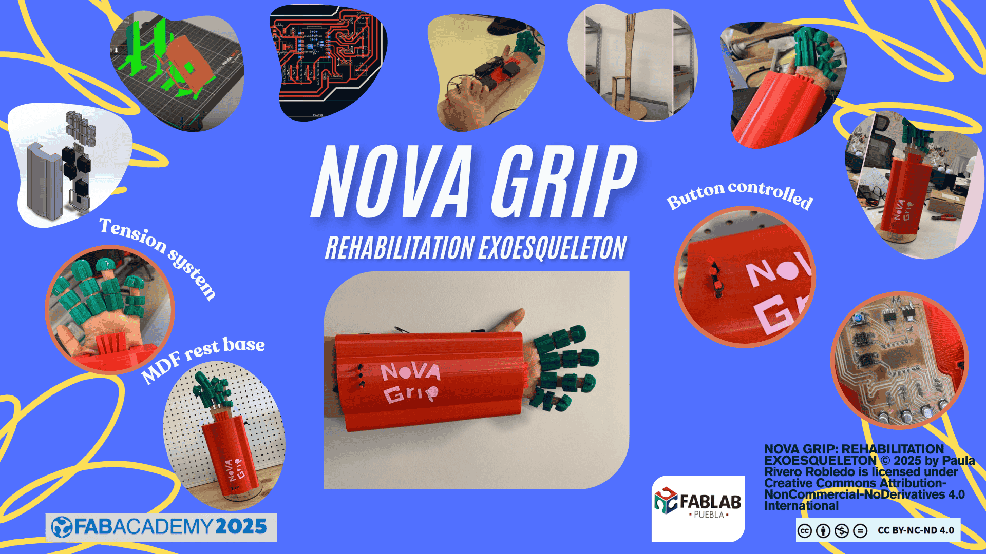
SKETCH
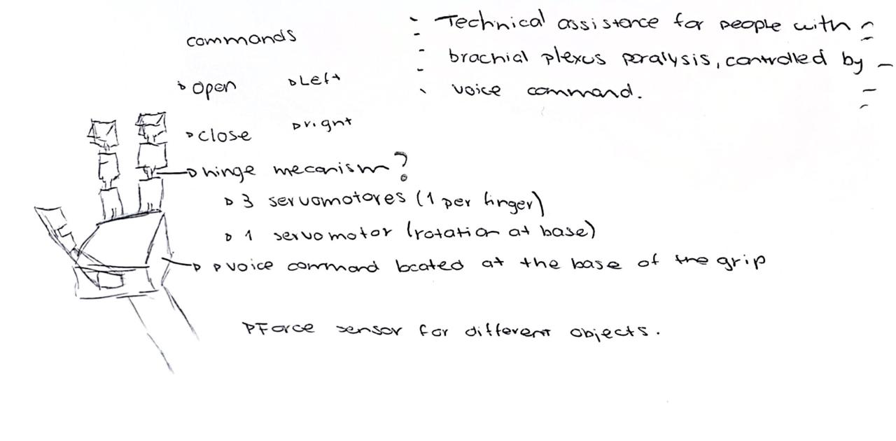
My final project is a wearable exoskeleton designed to assist in the rehabilitation of people with limited finger mobility. The main goal is to help users open and close their hand using a mechanical system controlled by buttons.
The device works as follows:
- Pressing one button will close the fingers.
- Pressing another button will open the fingers.
- A third button will return the hand to a neutral position.
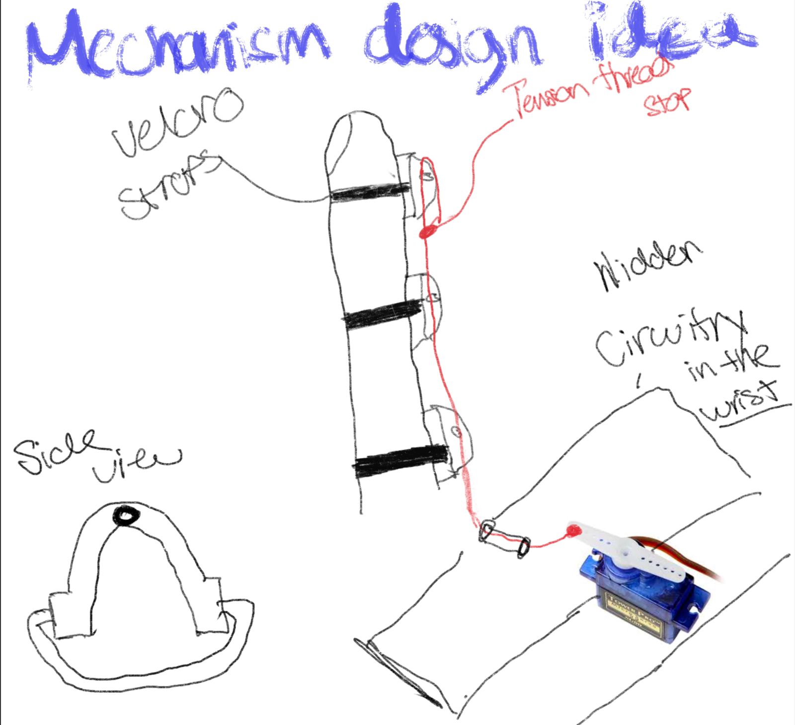
The mechanism is based on a tension system using strings connected to servomotors. When the motor rotates, it pulls the string, causing the fingers to move—similar to how tendons function. The goal is to create a device that is both functional and comfortable for the user.
Below are some of the initial design ideas. While I explored different options, I based the final prototype mostly on the second sketch, as it offers a better balance between functionality and comfort.
Research
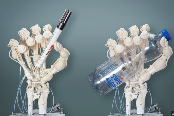
My design inspiration came mainly from the GrippLyfe glove, a robotic rehabilitation glove designed to assist hand movement, especially in patients with paralysis or muscle weakness. It works through soft pneumatic actuators that inflate with compressed air to flex the fingers in a controlled way. These actuators are connected to an air pump and solenoid valves that regulate the flow to each finger, controlled by a microcontroller. The system allows for smooth and safe movements, mimicking natural muscle function, and can be used in mirror mode to replicate the healthy hand's movements in the affected hand as part of active rehabilitation therapy.
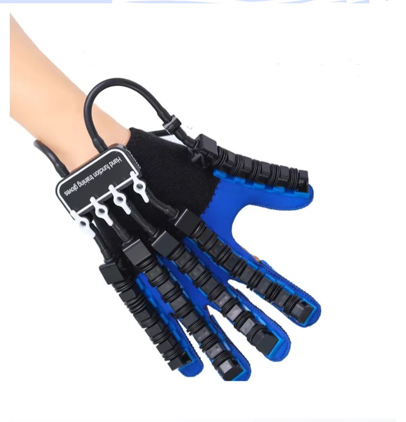
My design idea is to replicate that movement, but instead of using pneumatic actuators, I will use servomotors. These will be placed inside the arm, along with a wristband that attaches to the forearm. This is where I will place the board I designed in Week 8. I will discuss the board and its function later. The motors and the necessary buttons will also be there.
The device will function as a robotic glove or exoskeleton worn on the affected hand, designed to assist in movement and rehabilitation. It will use motorized actuators to mimic natural finger motion.
To begin the project, I designed the fingers. Since it is an exoskeleton, it needs to be comfortable and lightweight. I based the design on an artificial tendon system, similar to those in rehabilitation gloves. It mimics the natural biomechanics of the human hand, where forearm muscles pull tendons to move the fingers. In an artificial system, strong threads (like fishing line, Bowden cable, or nylon cords) are attached to the phalanges and routed through guides (such as 3D-printed rings) along the back of the fingers, replicating real tendon paths.
The end of the thread connects to an actuator (usually a servo or DC motor with a spool), which tightens the thread and flexes the finger when it turns, simulating muscle contraction. To return the finger to its original position, passive extension is used, such as elastic bands, springs, or gravity. This system allows for precise movements with low weight, low energy consumption, and high flexibility, making it common in wearable exoskeletons and robotic gloves. Moreover, since it is external, it does not require surgery or invasive interaction with actual muscles, making it ideal for medical rehabilitation or assistive applications.
Materials and Components
🔩 Electronics and Mechanical Components
| Component | Supplier / Link | Approx. Cost (MXN) | Approx. Cost (USD) | Notes |
|---|---|---|---|---|
| TPU Filament 1.75 mm (1 kg) | MercadoLibre | $320.00 | $17.78 | Flexible material for 3D printing the exoskeleton |
| Nylon Thread 0.60 mm (100 m) | MercadoLibre | $62.00 | $3.44 | Used as tendon for finger movement |
| AMS1117-5V Voltage Regulators (10 pcs) | MercadoLibre | $49.00 | $2.72 | Only a few units used |
| AMS1117-3.3V Voltage Regulators (10 pcs) | MercadoLibre | $49.00 | $2.72 | Only a few units used |
| 4 MG995 Servo Motor | MercadoLibre | $89.00 | $4.94 | High torque, ideal for finger movement |
| Female Header 40 pins (10 pcs) | MercadoLibre | $39.00 | $2.17 | For interconnecting modules |
| Male Header 36 pins | Steren | $15.00 | $0.83 | For soldering to circuit board |
| Phenolic Board 10x15 cm | Steren | $24.00 | $1.33 | Used for manual circuit assembly |
| 60/40 Tin-Lead Solder (17 g) | Steren | $25.00 | $1.39 | For soldering components |
🧰 Components Provided by the FabLab Ibero Puebla (Free of Charge)
| Component | Quantity / Use | Cost (MXN) | Cost (USD) | Notes |
|---|---|---|---|---|
| Xiao RP2040 | 1 unit | $0.00 | $0.00 | Main microcontroller |
| 4.7µF SMD Capacitors | Several | $0.00 | $0.00 | Used for voltage filtering |
| SMD PushButtons | Several | $0.00 | $0.00 | Used for user interaction |
💰 Total Estimated Cost
Purchased Components Total: $787.00 MXN (~$43.72 USD)
FabLab Provided Components: $0.00 MXN / $0.00 USD
Project Timeline
This timeline outlines the weekly tasks and milestones to complete the assistive exoskeleton for three fingers (thumb, index, and middle) using voice control and servomotors.
| Date | Task | Goal |
|---|---|---|
| May 13 – May 19 | Finalize design sketches, 3D model phalanges in SolidWorks | Have all CAD designs ready for printing |
| May 20 – May 26 | 3D print all components and test joint fit | Have functional mechanical finger structures |
| May 27 – June 2 | Assemble the system with servos, mount cables | Have a full working prototype structure |
| June 3 – June 5 | Integrate voice control and finalize code | Device responds to commands like "open" and "close" |
| June 6 – June 9 | Testing, adjustments, and final documentation | Prepare for final presentation and review |
Background and Learning Process
Throughout the development of this project, I integrated various skills and knowledge acquired in previous weeks of the Fab Academy. These experiences were essential to complete the design, fabrication, electronics, and integration of the wearable robotic hand.
2D and 3D Design
- Week 2 – Computer-Aided Design: I used the tools learned in this week to model the mechanical parts of the hand and forearm in SolidWorks. I also applied vinyl cutting techniques for aesthetic decoration of the device.
- Week 5 – 3D Scanning and Printing: I used these skills to manufacture custom 3D-printed parts, including the finger mechanisms and casing for the electronic components.
Additive and Subtractive Fabrication Processes
- Week 3 – Computer-Controlled Cutting: I used laser cutting to fabricate a stable base where the wearable device can be mounted or stored when not in use. This structure ensures the hand remains upright and secure, which is especially helpful for testing and presentation purposes.
- Week 5 – 3D Printing: I printed the finger segments and the mechanical casing using PLA filament, applying layer orientation and infill techniques learned during this week.
Electronics Design and Production
- Week 6 – Electronics Design: I designed my own custom PCB, considering the requirements for powering and controlling the servomotors.
- Week 8 – Electronics Production: I fabricated my board using the milling machine and tested its functionality for motor control and microcontroller programming.
Embedded Microcontroller Design, Interfacing, and Programming
- Week 10 – Output Devices: I applied PWM motor control to manage the movement of the fingers through servo motors, using embedded programming techniques.
System Integration and Packaging
- All components—mechanical, electronic, and structural—were integrated into a single wearable system. The casing and internal channels were designed to ensure cable routing, motor function, and aesthetic finish. I made sure the final prototype was compact, wearable, and easy to assemble or modify for future iterations.
Design & 3D Printing
Since this is a wearable device, I considered 3D printing for the user-centered design. This gave me greater flexibility when selecting shapes and materials.
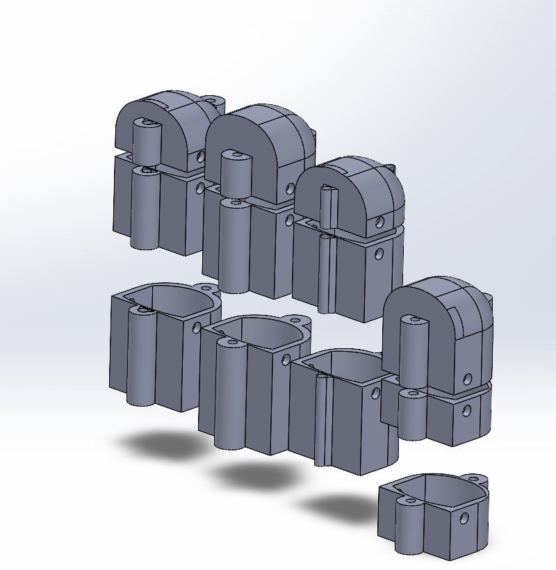
Fingers
For the fingers, I designed a segmented mechanism divided into three parts: the proximal, medial, and distal phalanges. I chose this configuration because a single rigid piece would not allow the finger to bend naturally. Human fingers work like hinges, and this segmented design makes the robotic fingers more comfortable and functional.
I created four fingers: index, middle, ring, and pinky. Each was designed based on measurements of my own hand to ensure proper fit and ergonomics. In future iterations, these dimensions could be standardized for general use or customized per user.
I also included small internal channels in each finger segment to guide a tension cable, which is pulled by motors to create finger movement.
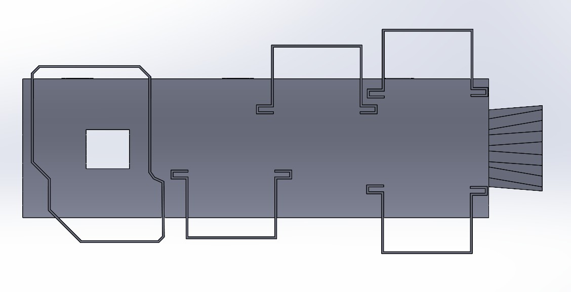
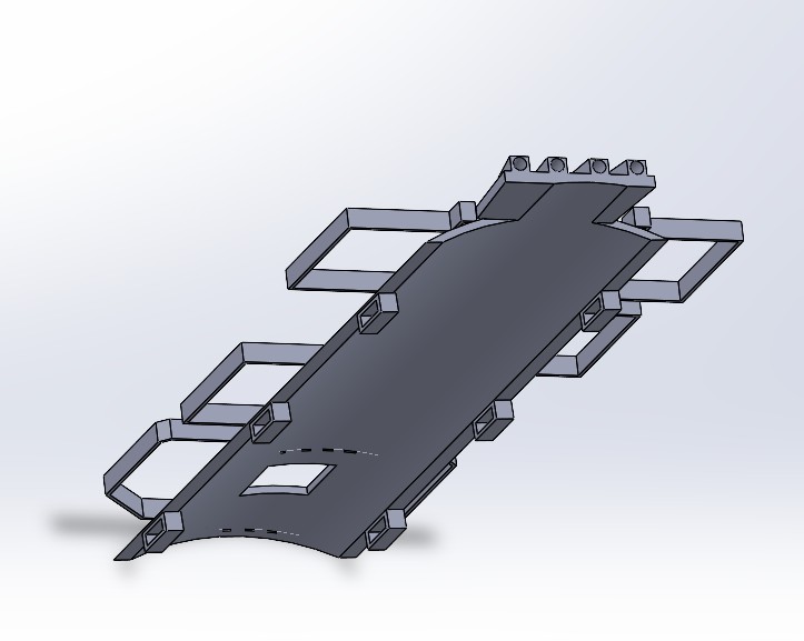
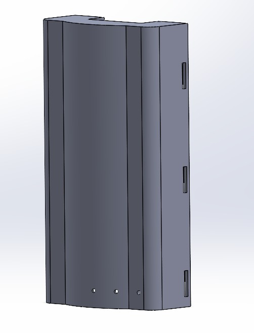
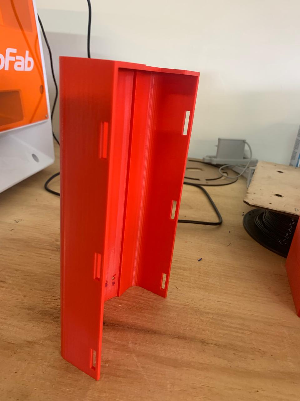
Forearm
I designed the forearm section to serve as the main support structure for the electronic components. This part includes housing for the microcontroller board, the battery, and the servomotors that control the cables attached to each finger. I took measurements of my own forearm to make sure the wearable fits securely and comfortably.
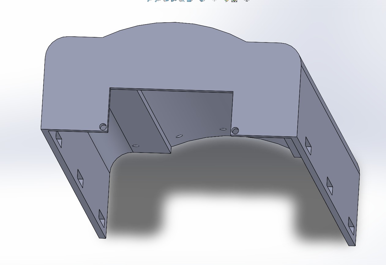
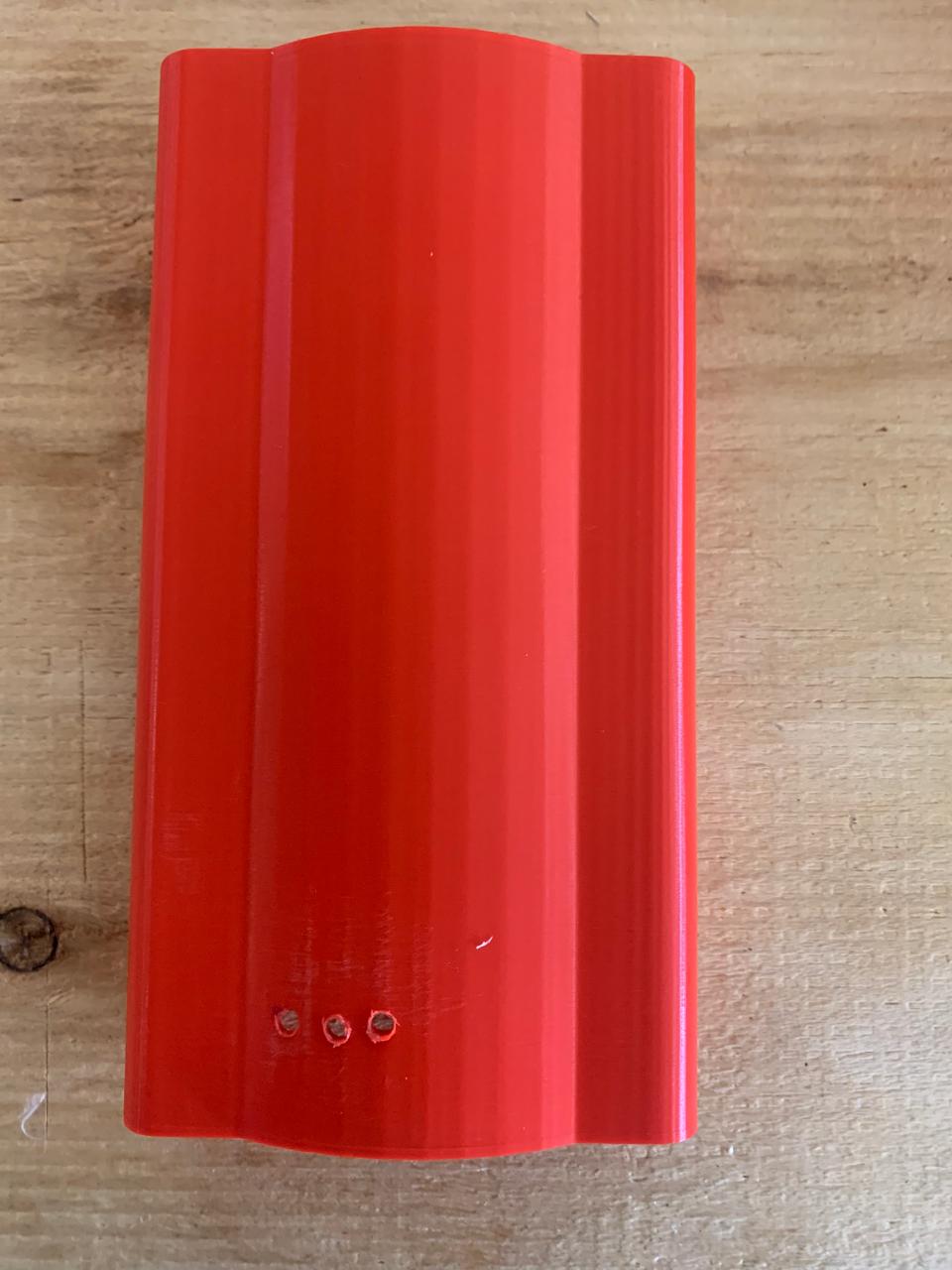
Casing
To improve aesthetics and safety, I designed a custom cover (or casing) that hides the motors and internal electronics. This enclosure protects the components from external damage and prevents accidental contact with moving parts. I ensured that the cover is removable for maintenance and inspection.
Forearm-Motor Assembly
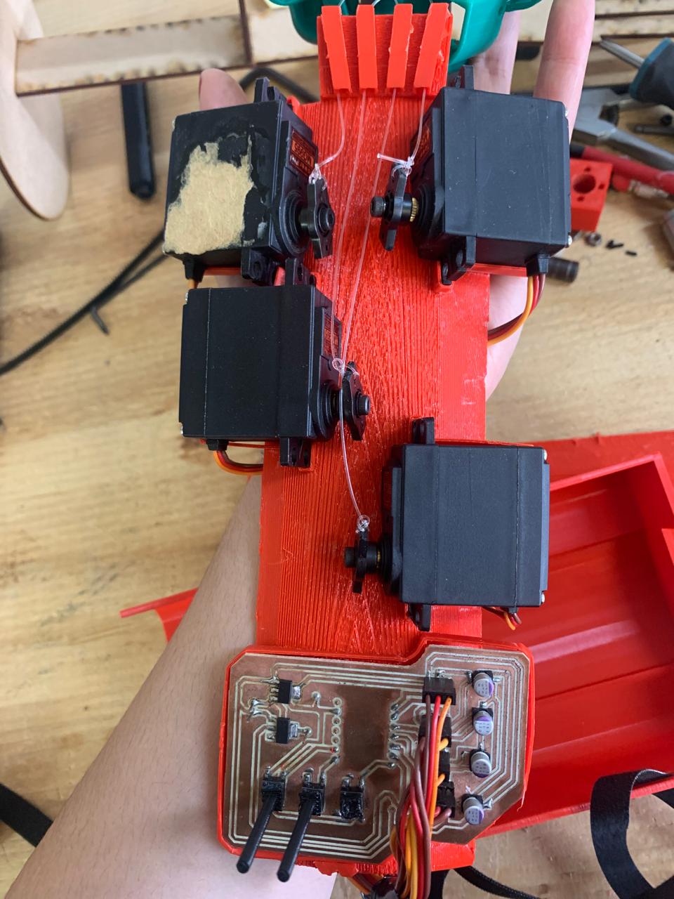
After finalizing the design in SolidWorks, I proceeded with the assembly phase. I positioned the servomotors inside the forearm section and connected each to its respective cable routed through the finger channels. The base of each cable was secured near the fingertips, while the motors pull from the forearm to create tension and achieve flexion.
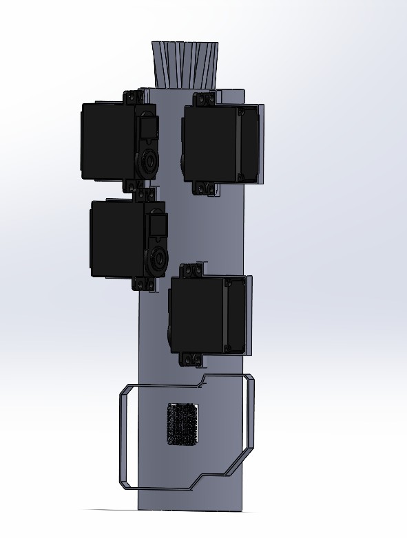
Cable guides and pulleys were added to optimize movement and reduce friction, ensuring smooth and responsive control.
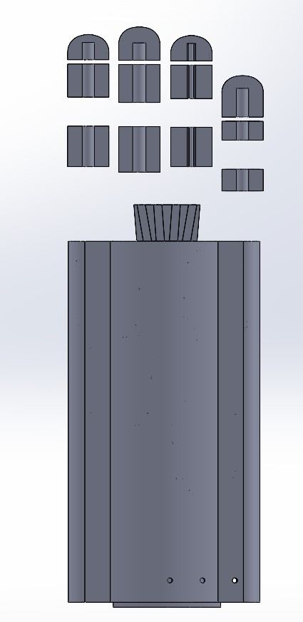
Full CAD Assembly
Once the fingers, forearm, and casing were completed, I assembled the full wearable device. The final prototype integrates all mechanical and electronic elements into a compact and functional form. The system is powered by a rechargeable battery and can be controlled via a microcontroller, making it suitable for further testing in rehabilitation or assistive applications.
3D PRINTING
3D Printing
For the fingers, I selected TPU (Thermoplastic Polyurethane) due to its excellent flexibility and comfort, which are crucial for wearable applications that interact directly with the human body.
Before printing, I dried the TPU filament at 55°C for about 4 to 6 hours to reduce stringing and improve the surface finish. This step is essential to achieve clean, precise results with flexible materials.
I used a Bambu Lab A1 3D printer, which offers excellent handling of flexible filaments and high-resolution output, making it ideal for printing small mechanical parts like finger joints.
These were the printing parameters I used:
- Material: TPU
- Nozzle temperature: 230°C
- Bed temperature: 60°C
- Print speed: 25 mm/s
- Cooling fan: 100%
- Retraction distance: 1.5 mm
- Retraction speed: 20 mm/s
- Layer height: 0.2 mm
- Infill: 20%
Forearm and Casing – PLA
For the forearm structure and the motor casing, I used PLA (Polylactic Acid) due to its strength, ease of printing, and stability. These parts needed to be rigid to support the electronics and provide a secure enclosure for the motors.
I used a Prusa MK4S printer with PrusaSlicer software to generate the G-code. This setup gave me excellent control over parameters and consistent results for the mechanical parts of the wearable.
Although PLA is less sensitive to humidity than TPU, I kept the filament stored in a dry box to avoid surface imperfections.
Printing parameters for PLA:
- Material: PLA
- Nozzle temperature: 215°C
- Bed temperature: 60°C
- Print speed: 50 mm/s
- Cooling fan: 100%
- Retraction distance: 0.8 mm
- Retraction speed: 25 mm/s
- Layer height: 0.2 mm
- Infill: 25%
Forearm
Casing
Board Design and Electronics Production
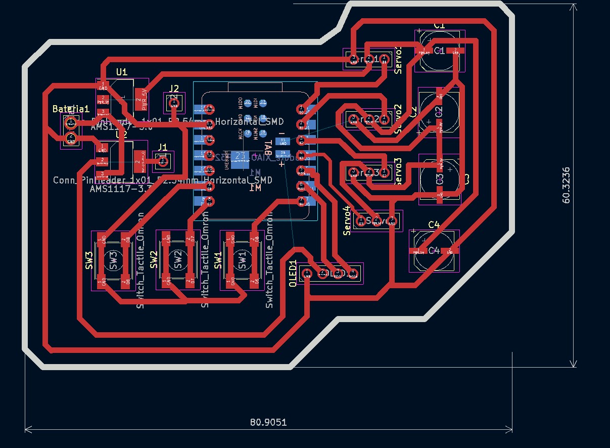
To control the motors and organize all the electronic components, I designed a custom PCB using KiCad, a tool I learned to use during Week 6 – Electronics Design.
I decided to use MG995 servomotors because they provide higher torque compared to smaller alternatives. This strength was necessary to move the fingers once the tensioning cable was in place. For motor control, I used a Xiao RP2040, which is compact and capable of generating multiple PWM signals.
The circuit includes three push buttons:
- Open hand
- Neutral position
- Extend hand
I also included 100 µF capacitors in parallel with the motors to prevent dangerous voltage spikes due to back EMF. For modularity, I used male and female pin headers for connecting the components and peripherals like the OLED display.
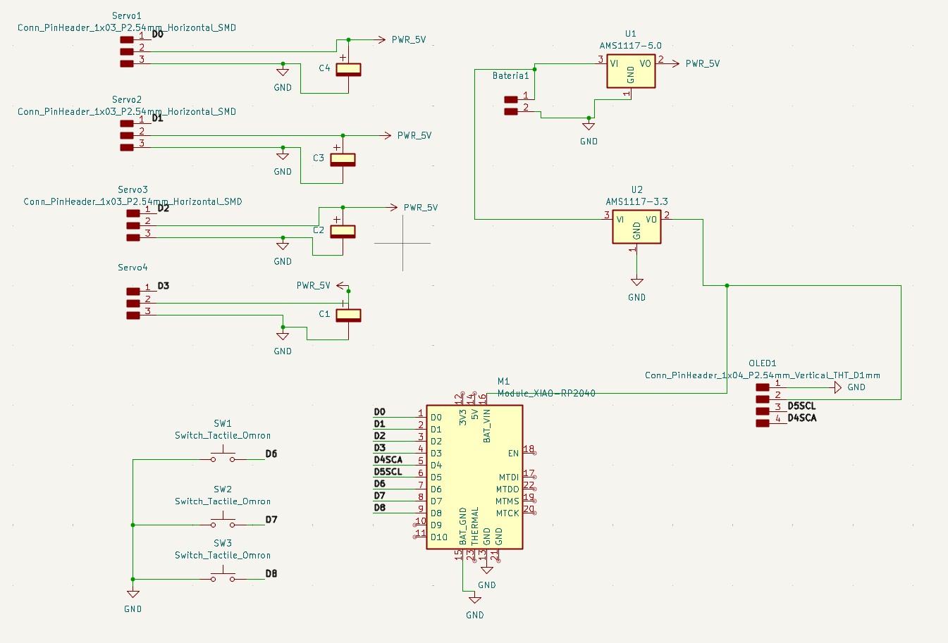
I needed a board that was compact yet functional, so I designed a 80x60 mm PCB that fits neatly inside the forearm housing.
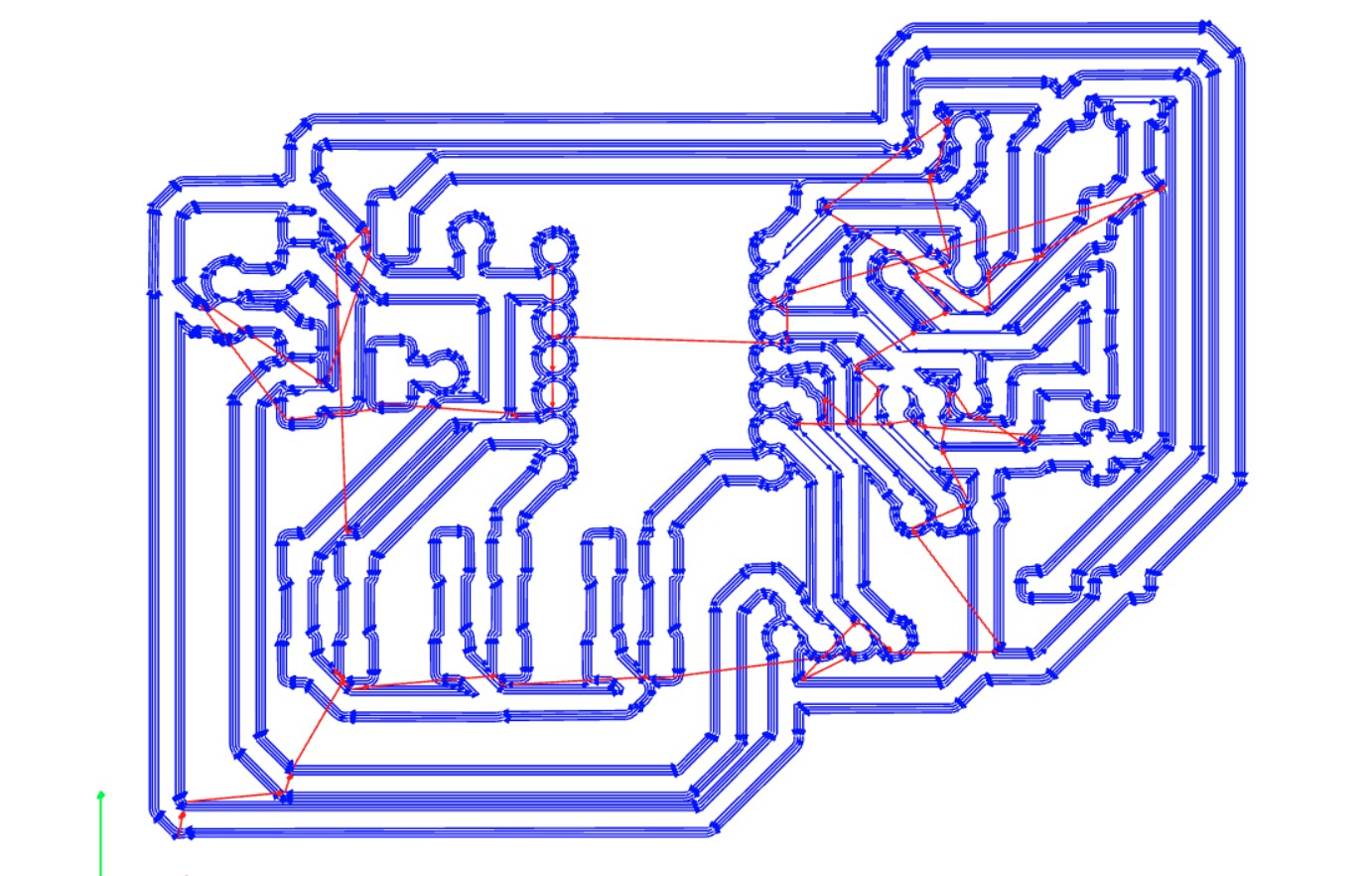
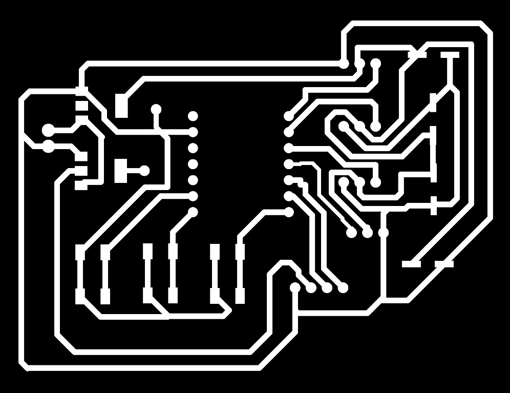
I applied the knowledge gained from Week 8 – Electronics Production to manufacture the board. I used MODS to generate the necessary files for milling: edge cuts, drill holes, and traces. Then, I milled the board on a Roland Monofab SRM-20 using a phenolic copper-clad substrate.
For the milling process, I used a 1 mm flat end mill to cut the traces, a 0.8 mm drill bit to create the holes, and a 0.8 mm V-shaped cutter for the edge cuts.
Traces
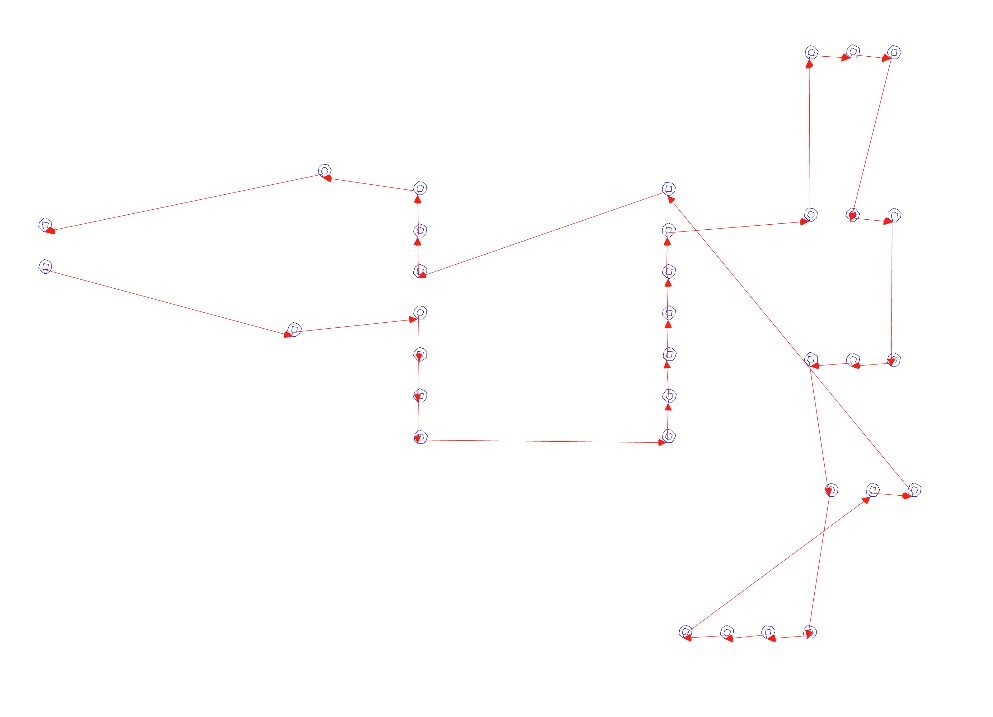
Holes
Edge Cuts
PCB Milling Video
Final Cut PCB
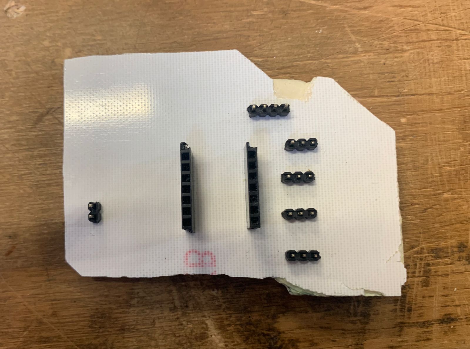
Soldering
Once the PCB was milled, I proceeded with the soldering process. I used the following components to populate the board:
- Male pin headers – for connecting the servomotors.
- Female pin headers – to plug in the Xiao RP2040 securely.
- 4 SMD capacitors of 100 µF – placed near each motor for voltage stabilization and to suppress back EMF.
- 3 SMD push buttons – to control the hand functions (open, neutral, extend).
- Soldering tin (solder wire) – used with a soldering iron for component attachment.
- AMS1117 5V voltage regulator – used to power the servomotors from a 7.2V LiPo battery.
- AMS1117 3.3V voltage regulator – used to safely power the Xiao RP2040 from the same battery source.
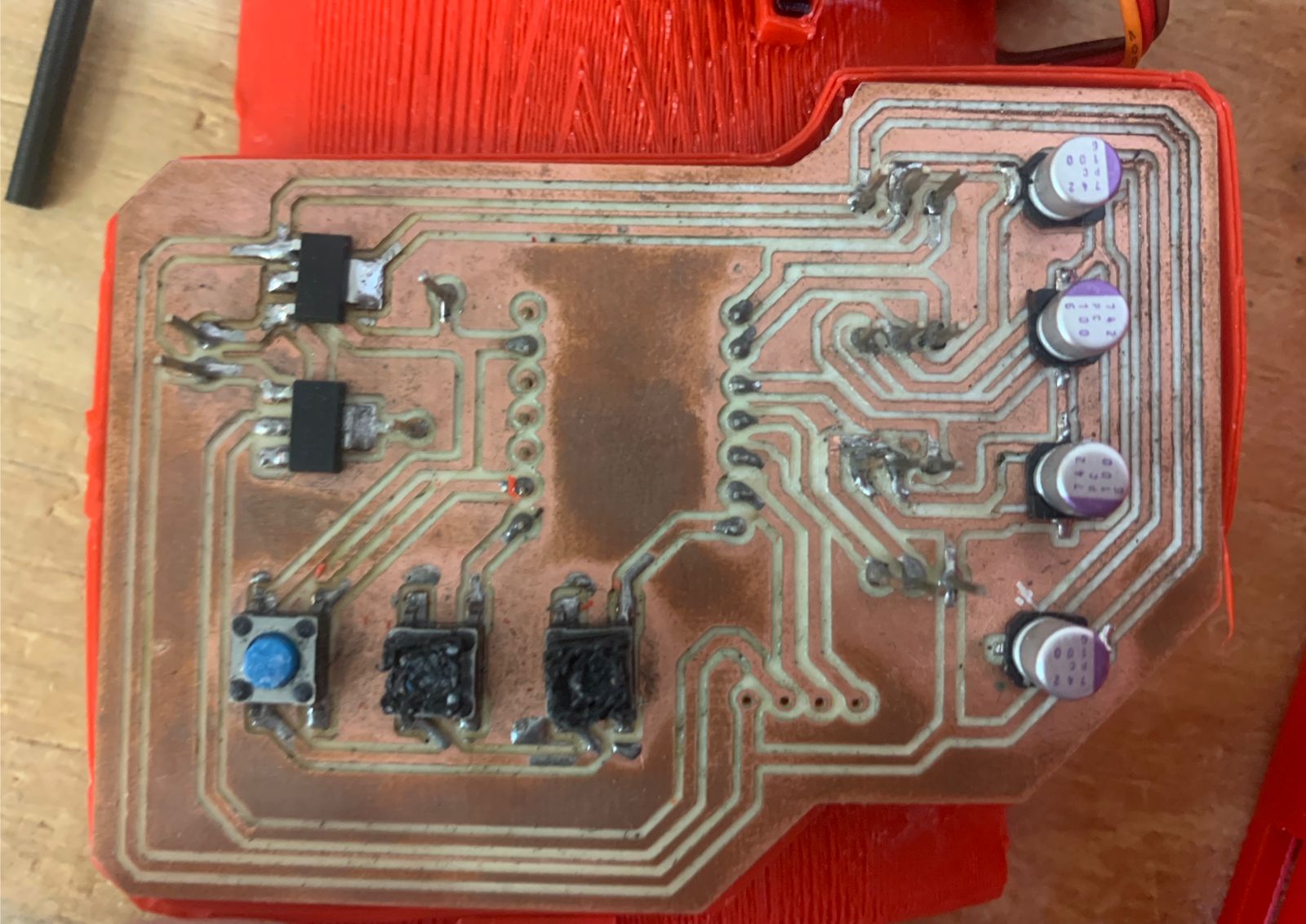
The regulators ensured that both the microcontroller and the motors received the correct voltages during operation. I carefully soldered all components onto the board, paying special attention to polarity and orientation for the regulators and capacitors.
Final soldered PCB
Assembly and Electronic Testing
Once the PCB and all electronic components were ready, I began assembling the robotic hand. I started by mounting the MG995 servomotors into their designated motor housings inside the forearm structure. Then, I placed the custom PCB into its slot and connected all necessary wires using the pin headers.
After all connections were secured, I proceeded to tension the fingers using the motors and nylon cable. Each motor was linked to a finger, allowing individual movement. Once the mechanical assembly was complete, I moved on to testing.
For the initial test, I uploaded a simple Arduino code to verify that each motor responded correctly to basic commands. Here is the test code I used:
See the Pen Untitled by Paula Rivero (@Paula-Rivero) on CodePen.
Servo Testing 1
Servo Testing plus assembly
See the Pen Untitled by Paula Rivero (@Paula-Rivero) on CodePen.
And here is the final functionality test of the fully assembled and working robotic hand:
Final Assembly
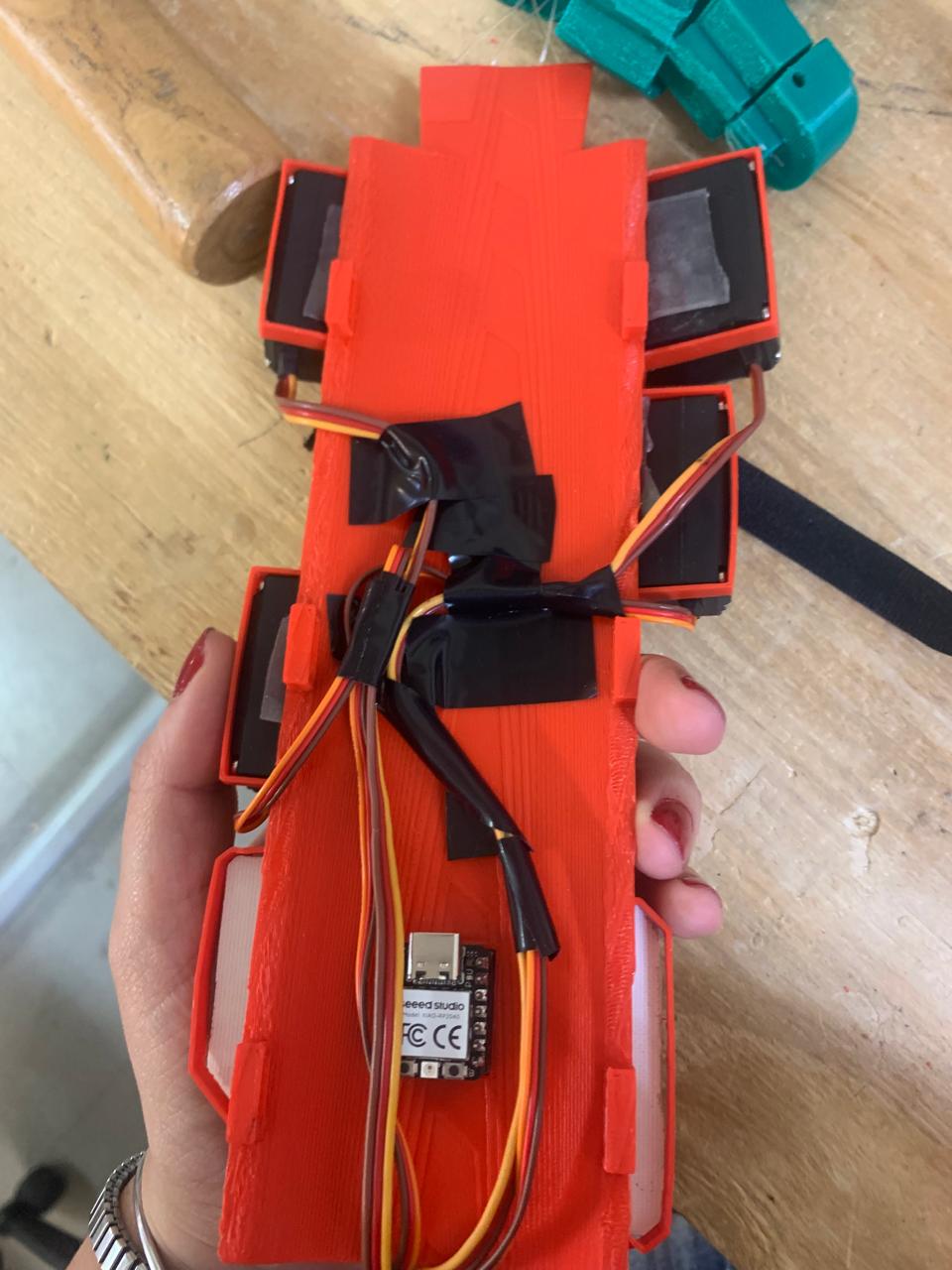
After finishing the electronic tests and confirming that all components were working properly, I proceeded with the final assembly of the robotic hand.
First, I organized and secured all the wiring inside the forearm casing to avoid any interference with the moving parts. Then, I mounted the final PCB in its dedicated slot and connected the battery, ensuring it could be easily accessed for charging or replacement.
I inserted each finger cable through the designed guides and verified that the movement range was not obstructed. Then, I attached the top cover of the forearm using screws and checked that all structural parts were tightly secured.
Lastly, I tested the complete system again to ensure that the motor control, button responses, and overall mechanical performance were functioning as expected with the final enclosure in place.
The result is a fully integrated and wearable robotic forearm that demonstrates both mechanical and electronic functionality. This final version allows for intuitive control via buttons and is designed to be modular and maintainable.
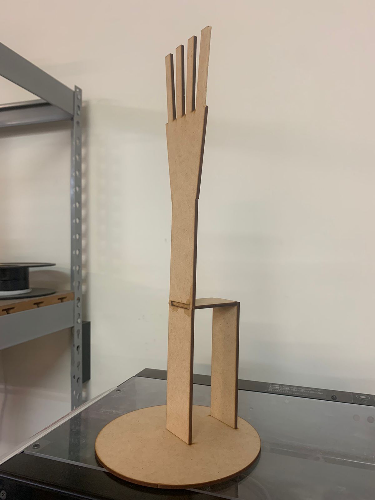
Base Design in 2D – MDF Structure
To support the robotic forearm in a stable and presentable way, I designed a custom base using SolidWorks. The design consists of interlocking pieces that hold the arm upright and slightly elevated for display and testing.
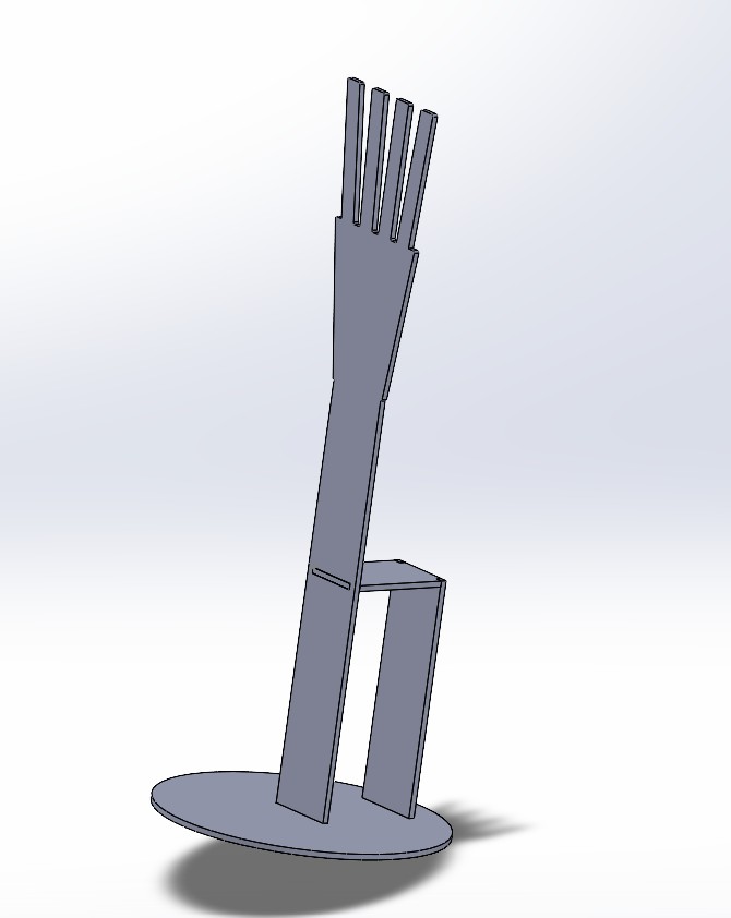
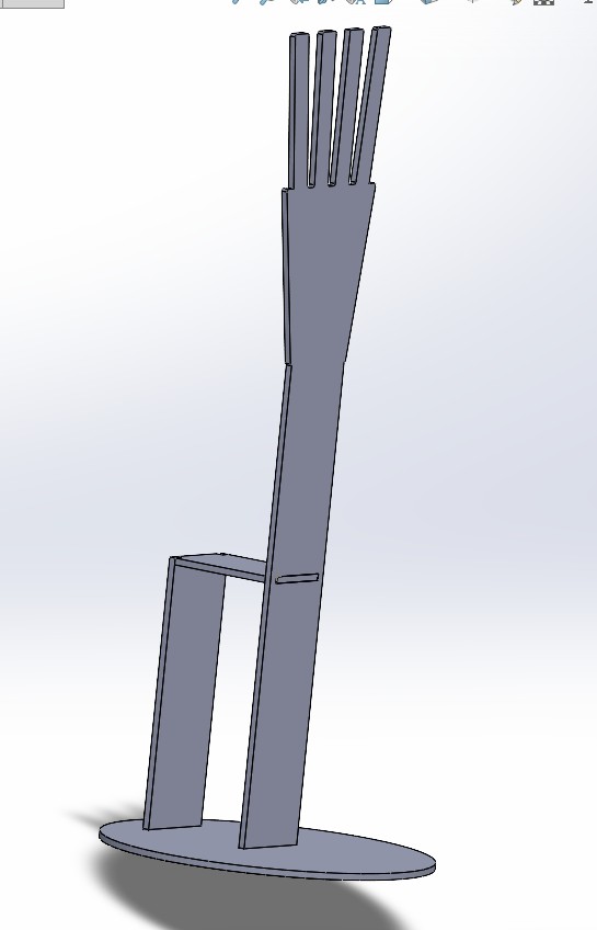
Applying the knowledge I gained during Week 3 – Computer-Controlled Cutting, I exported the design as a 2D DXF file and prepared it for laser cutting.
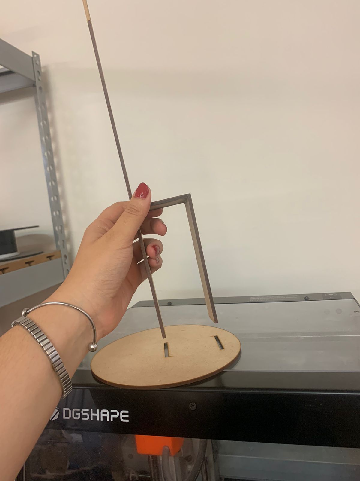
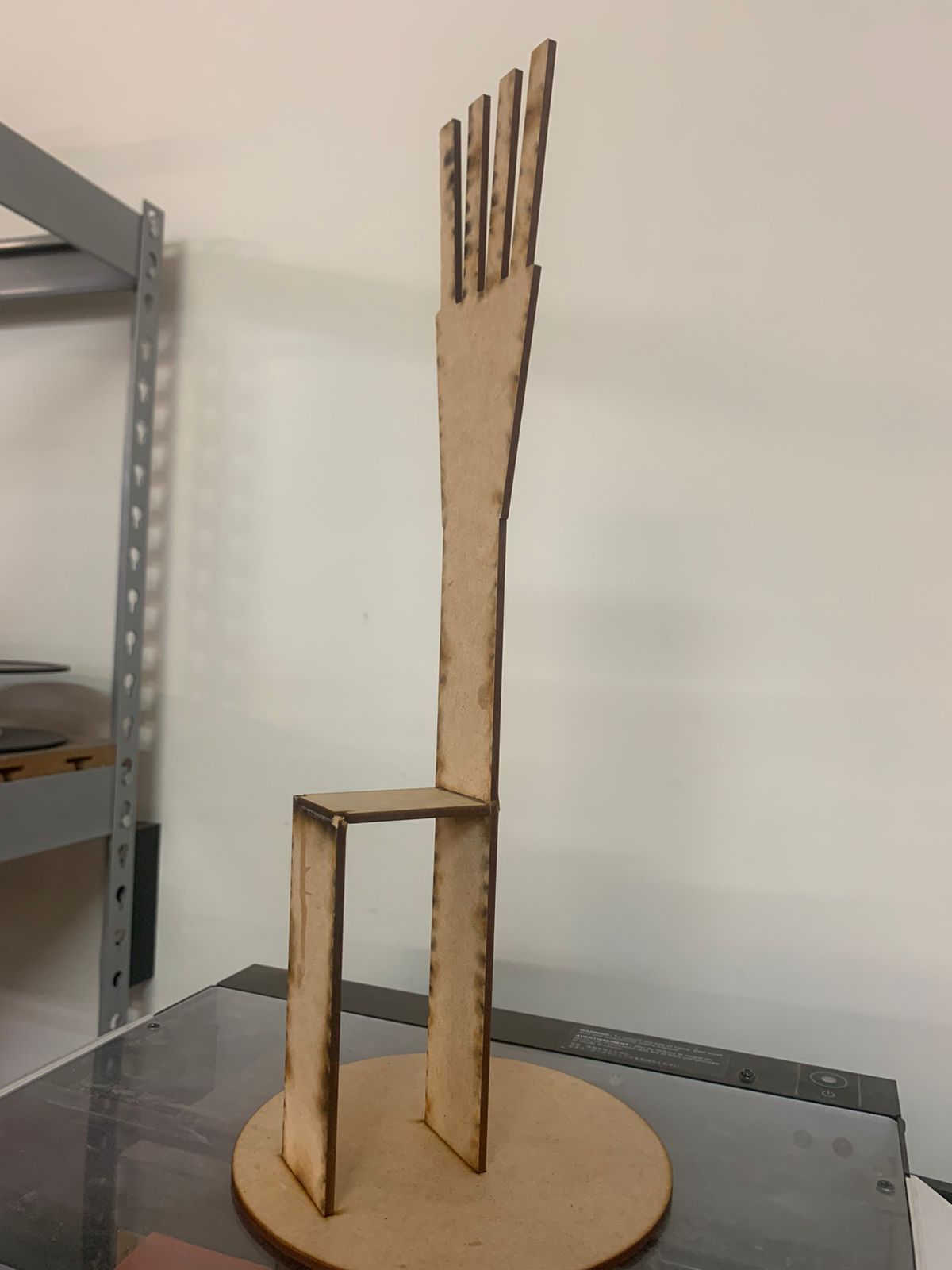
I used 3mm MDF as the material and left a 0.03 mm kerf offset to ensure that the pieces would fit tightly together without the need for glue or screws.
The parts were cut using the laser cutter available in the lab, and the results were very accurate. Once cut, I assembled the base without any issues. The press-fit joints were precise, and the structure felt stable and well-balanced.
This MDF base not only holds the forearm in place but also provides a clean and professional look for demonstration and final presentation purposes.
Logo Design and Vinyl Cutting
As part of the final aesthetic of the forearm device, I designed a custom logo that would be placed on the external case. Using the skills I developed during Week 3 – Computer-Controlled Cutting, I created the logo using Inkscape, preparing it as a vector file in SVG format.
I aimed for a clean and modern design that reflects the purpose and identity of the project. In Inkscape, I defined the shapes and typography, keeping in mind contrast and readability once applied over the PLA casing.
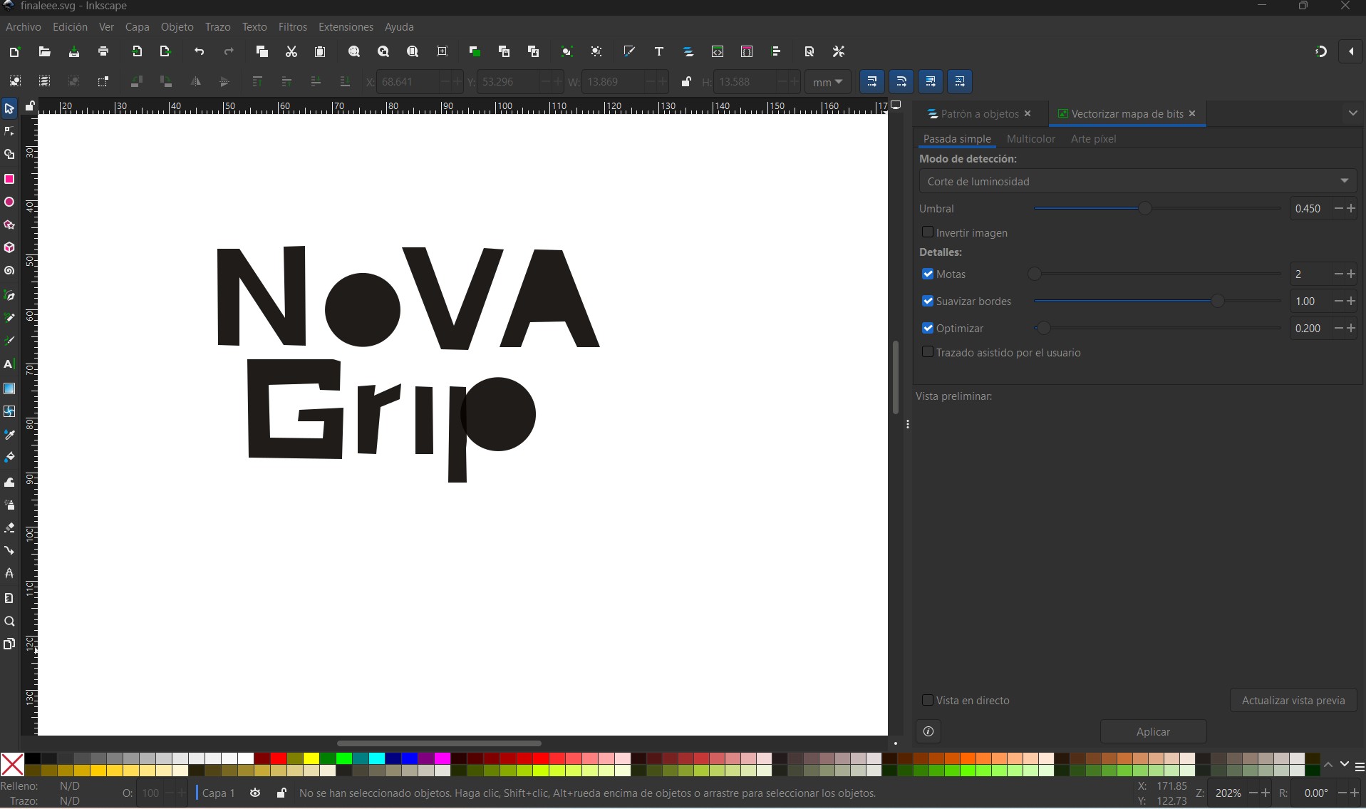
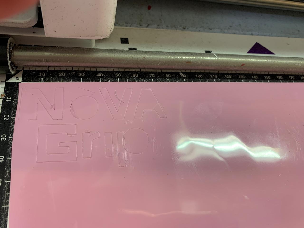
Once the SVG was ready, I exported it and used the Brother ScanNCut SDX225 Vinyl Cutter to cut the logo onto adhesive vinyl. This process was smooth thanks to the machine's built-in screen and precise blade control.
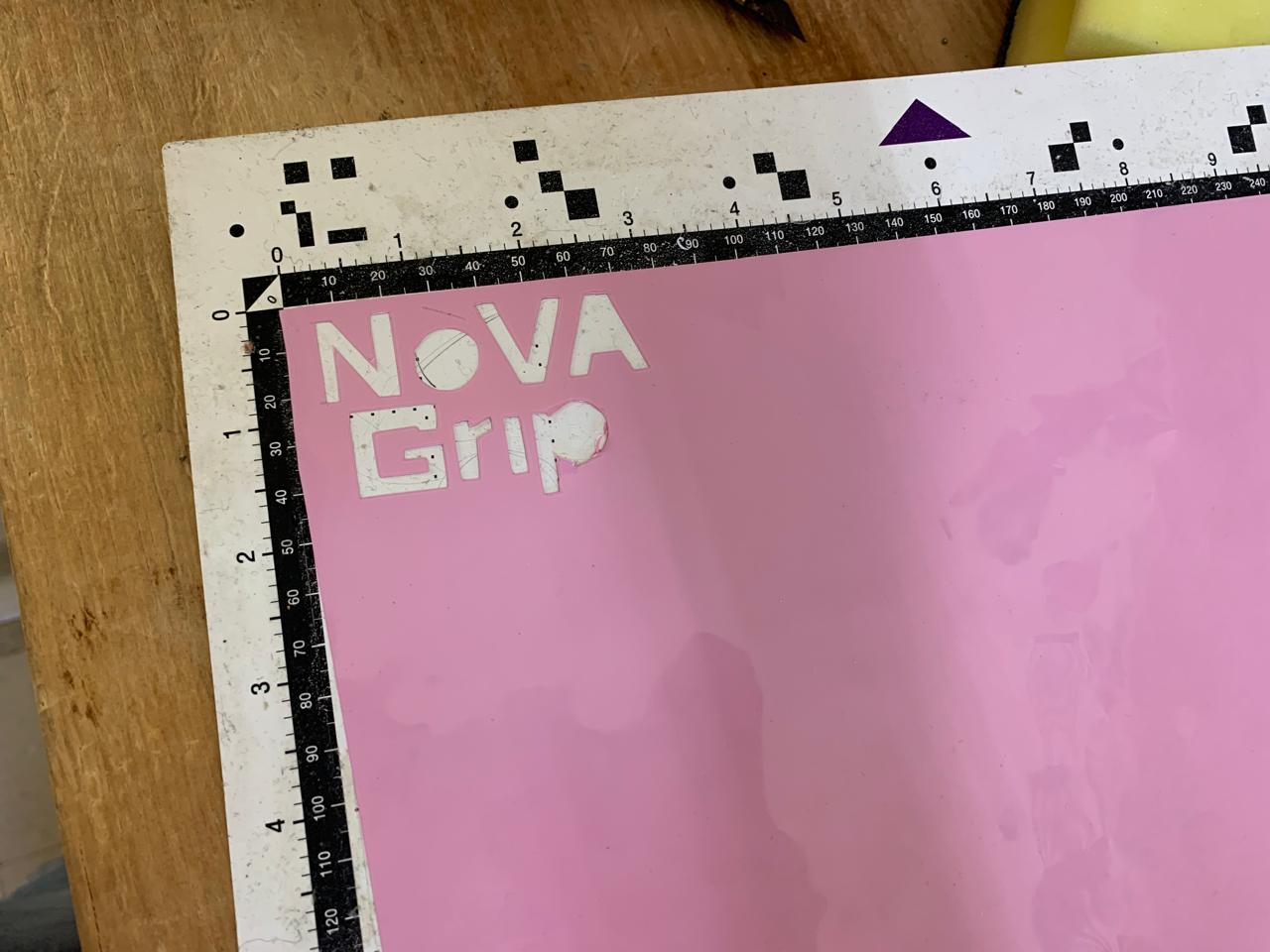
I aligned the vinyl correctly on the mat, adjusted the cut depth, and let the cutter trace the shapes of the logo. After that, I carefully weeded the excess vinyl and transferred the logo onto the 3D printed PLA forearm casing using transfer tape.
After this process, the result looked like this:
Then, I removed the pins and integrated the entire vinyl-decorated part into my final project:
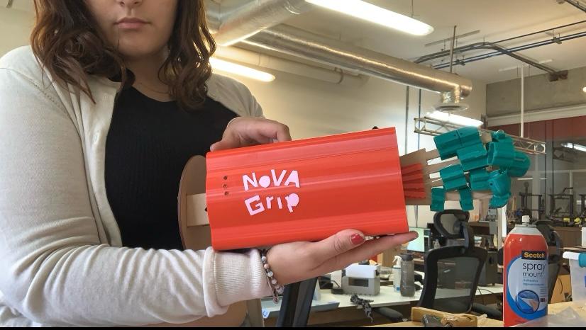
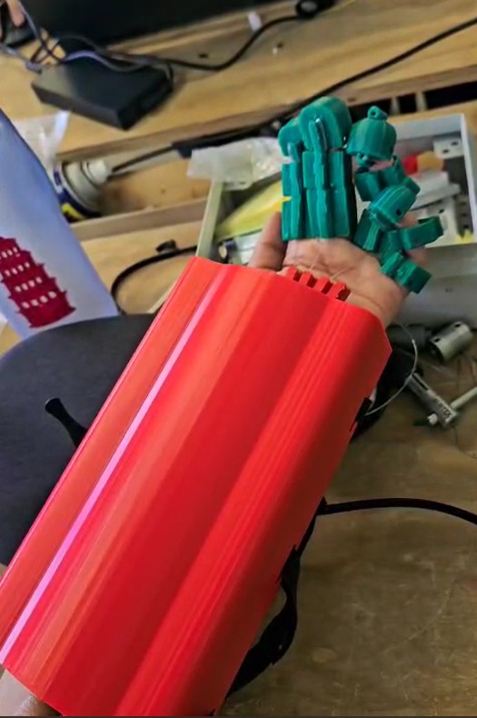
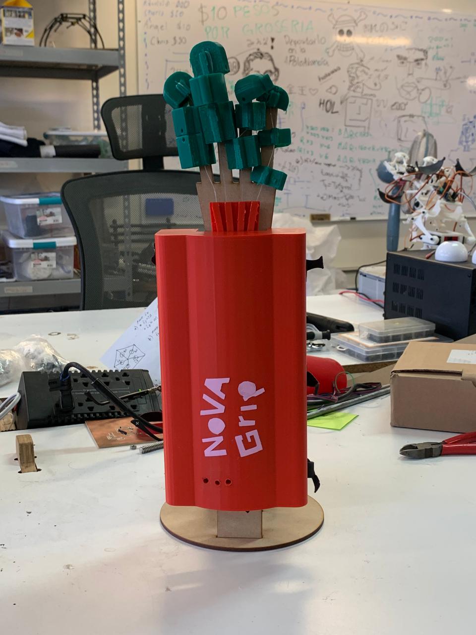
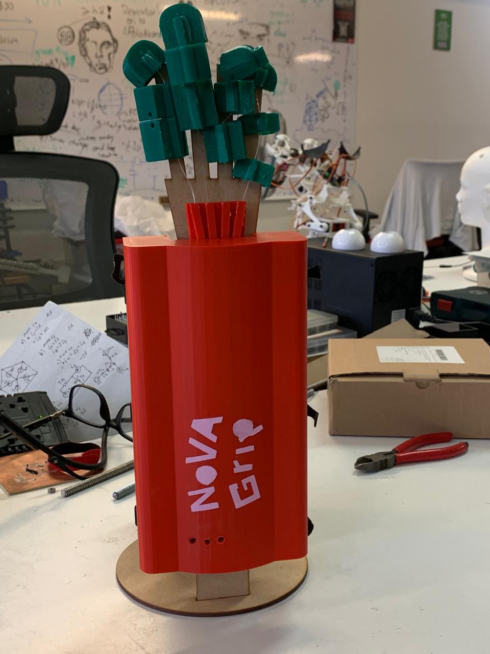
And here is the final completed project, fully assembled and functional:
Final Project Conclusion
Over the course of the Fab Academy, I developed a functional and wearable exoskeleton hand designed to assist patients with limited finger mobility, particularly those undergoing rehabilitation after brachial plexus injuries. The device allows users to open, close, and return their fingers to a neutral position through the use of buttons. A tendon system, powered by servo motors and nylon thread, enables smooth and controlled finger movement. The final design prioritizes both functionality and user comfort, and was iteratively improved based on testing and feedback.
Throughout this journey, I not only built a physical prototype—I built confidence in my ability to design, fabricate, program, and integrate complex systems. I learned how to:
- Use 2D and 3D design software to model parts and print them using flexible materials like TPU.
- Design and fabricate PCBs tailored to my specific needs using KiCad and milling machines.
- Program microcontrollers such as the Xiao RP2040 and ESP32C3 to control servos and manage user input through push buttons.
- Implement electronic circuits with voltage regulators, headers, and soldered connections to create a reliable embedded system.
- Apply networking and communication protocols like UART to connect components and enable system coordination.
- Document every step clearly and thoroughly, both for personal reflection and to share knowledge with others.
More than just technical skills, Fab Academy helped me grow as an engineer, thinker, and maker. It taught me how to prototype under pressure, troubleshoot creatively, and believe in the power of iteration. I am proud of what I created—not because it’s perfect, but because it works, and because it represents how much I have learned in such a short time.
This exoskeleton is not just a final project. It’s a foundation for future research, improvement, and perhaps, real-world application. And it’s only the beginning.
📁 Project Files
LICENSE
I chose the Creative Commons Attribution-NonCommercial-NoDerivatives 4.0 International (CC BY-NC-ND 4.0) license for my final project NOVA GRIP: Rehabilitation Exoskeleton because it protects my work while allowing others to share it under specific conditions that reflect my intentions as a creator.
🔒 Why this specific license?
- BY (Attribution): I want anyone who uses or shares my project to give me proper credit. This ensures recognition for my work and intellectual contribution.
- NC (NonCommercial): I do not authorize commercial use of my design or documentation. That means no one is allowed to profit from my work without my permission.
- ND (NoDerivatives): I do not allow modifications or adaptations of my project. This is especially important because the exoskeleton is intended for rehabilitation, and any changes could affect safety or effectiveness.
🌐 In summary:
✔ It can be downloaded and shared as-is
✘ It cannot be modified
✘ It cannot be used commercially
✔ I must always be credited as the author
NOVA GRIP: REHABILITATION EXOESQUELETON © 2025 by
Paula Rivero Robledo is licensed under
CC BY-NC-ND 4.0
![]()
![]()
![]()
![]()