3D Scannning and printing
This week at Fab Academy, we learned how to scan and print in 3D. This week's assignment is very interesting and creative, and the possibilities with 3D printing and scanning are endless. The only limit is our imagination.
Group Assignment
In Week 5 of Fab Academy, I learned about different 3D printing technologies, including SLA, SLS, FDM, and DLP. These technologies allow the creation of physical objects by adding material layer by layer. FabLab Puebla has a variety of 3D printers, including Ender 3 and Elegoo Mars, which offer different features for various printing needs. The goal was to explore and test design rules and optimize the use of these machines for rapid prototyping.
We tested tolerances, material thickness, and other parameters...
For more details, visit the Group Assignment Page.
Individual Assignment
- Design and 3D print an object (small, a few cm³, limited by printer time) that could not be made subtractively.
- 3D scan an object (and optionally print it).
3D Printing Assignment
Design and 3D Print an Object
For this week's individual assignment, we were tasked with designing and 3D printing an object (small, a few cm³, limited by printer time) that could not be made subtractively. This means the object should not be easily manufacturable using subtractive methods like milling or turning.
I decided to use SolidWorks for the design. SolidWorks is a powerful 3D CAD software widely used in engineering and industrial design. It offers advanced features for parametric modeling, simulation, and manufacturing (requires a license)
You can download it from the following link: Download SolidWorksMy Design Choice
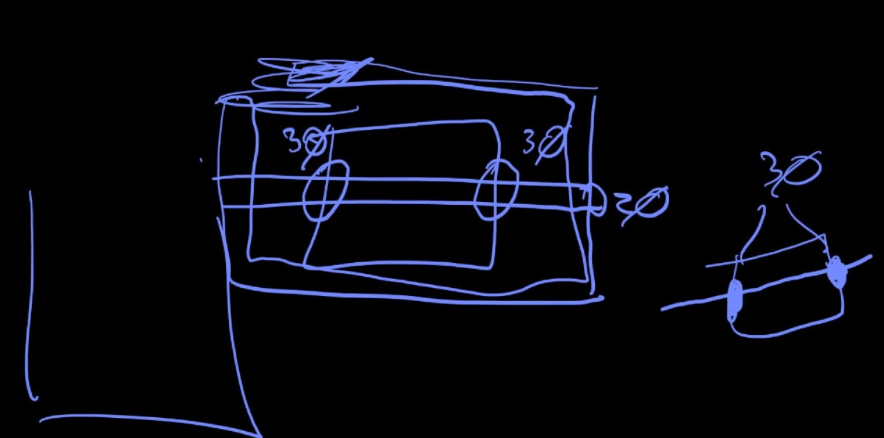
I chose to create something relatively simple yet effective: multiple floating frames, one inside another, all rotating on the same axis. Here is my first sketch of my idea.
Non-Subtractive Piece
My piece consists of nested cubes that interlock without the need for assembly. It is considered non-subtractive because it was fabricated using additive manufacturing (3D printing) rather than carving material away. Traditional subtractive methods, such as CNC milling, would struggle to create this design due to its internal structures.
Design and Printing Process
Below are the steps I followed to design and print the object:
- Step 1: Creating the base frame structure in SolidWorks.
To create the base of our figure, we first select the plane we will work on. I chose the "plant" plane and then created a sketch.
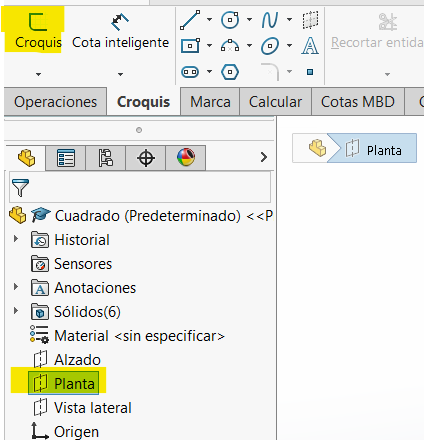
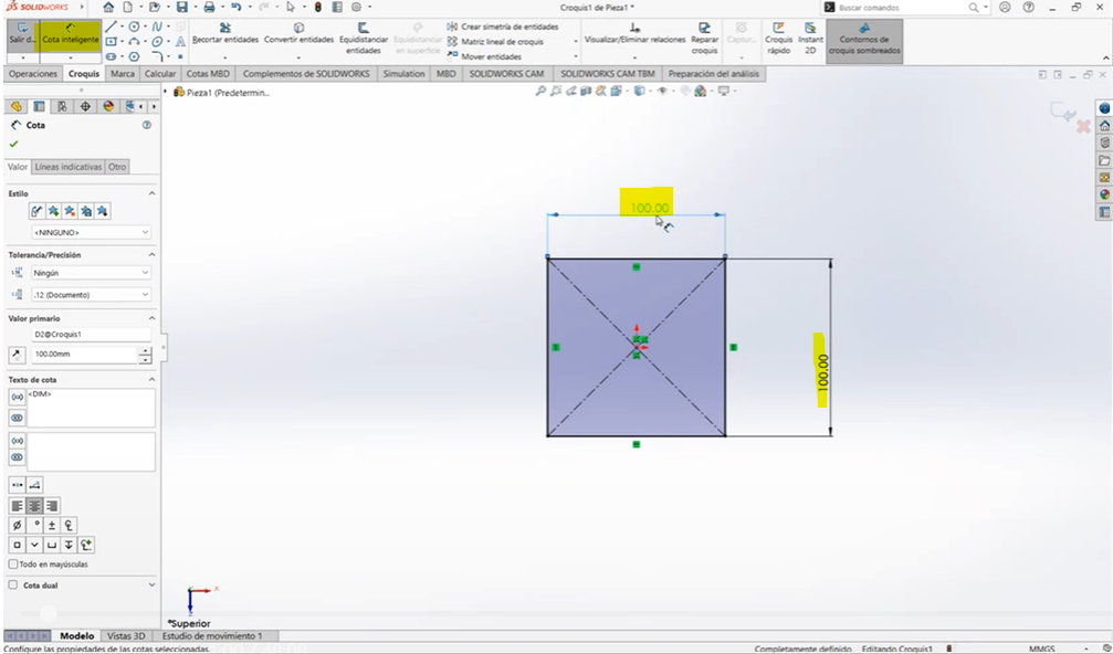
This is where we start designing. Then, using the center rectangle tool, we create a rectangle. After that, with the smart dimension tool, I set a width and height of 100mm x 100mm.
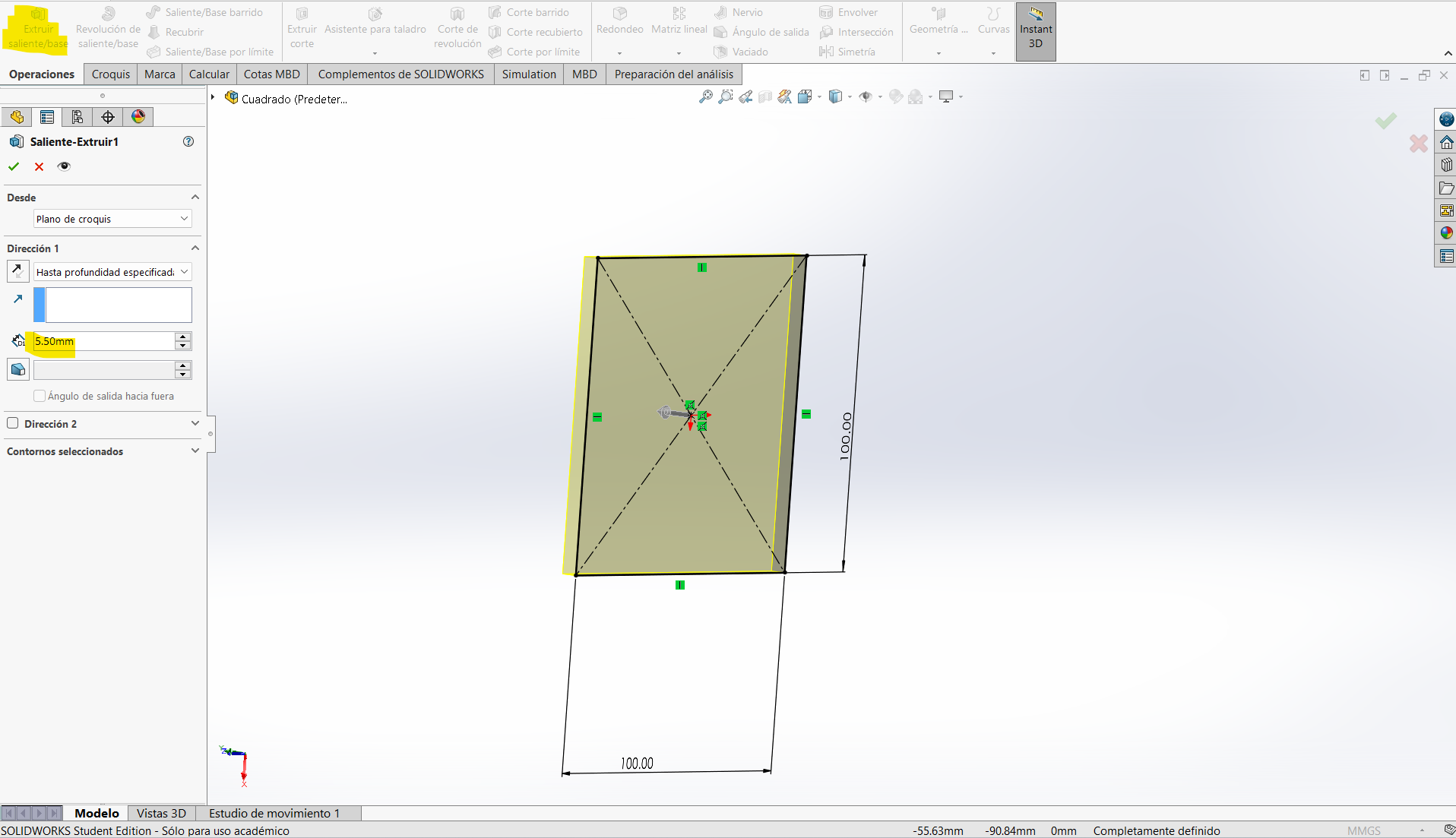
Finally, using the extrude base tool, I extruded the square to a height of 5.50mm, which will be the width of the figure and the print.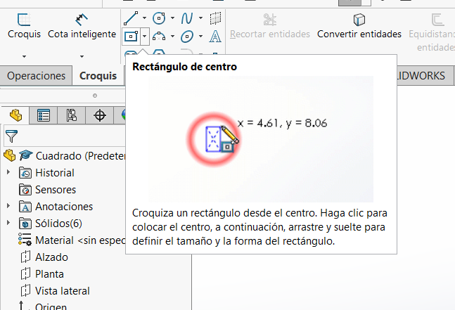
- Step 2: Adding inner rotating frames inside the main frame.
Once we have the extruded main square, we repeat the same process on a new sketch and plane, using the center rectangle tool. Using the smart dimension tool, we leave a 5.00mm gap between the 100x100mm square and the newly created one.
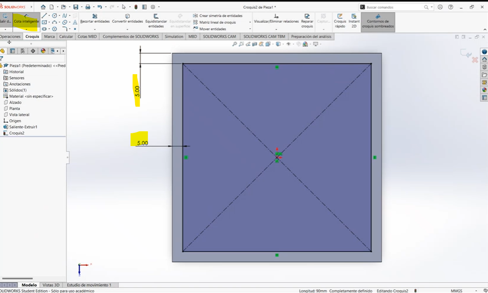
Then, we use the extrude cut tool to cut the space, creating our first inner square, which will serve as the base of our structure.
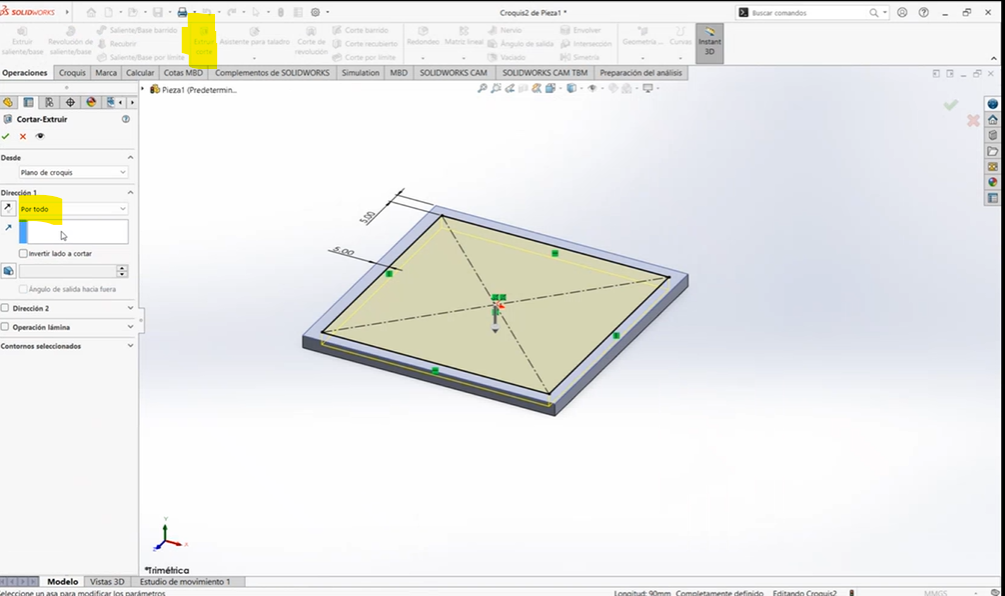
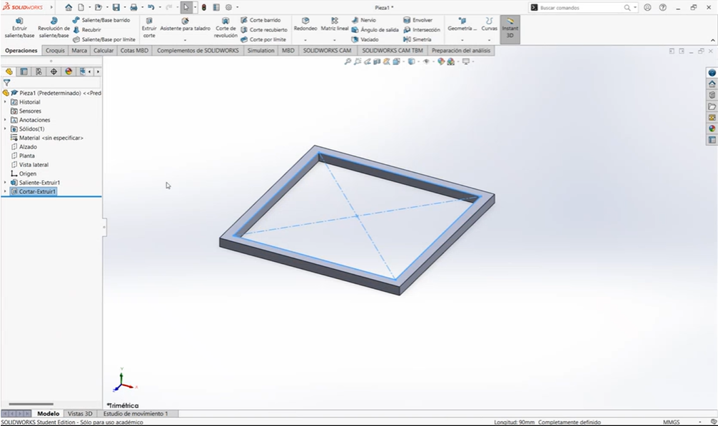
We repeat this process as many times as needed, maintaining a 3mm gap between squares to allow free rotation.
- Step 3: Ensuring proper clearances to allow smooth rotation.
After creating all squares, we align them on the same plane. Initially, I mistakenly stacked them upwards, forming a pyramid
To fix this, we edit the extrude base operation and select "vertex" under the "from" option, choosing the bottom vertex of the base square. We repeat this for all extrude base operations to properly align them.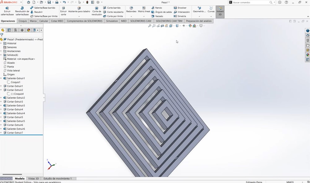
Next, we select a face of the second square, create a sketch, and draw a centered 4.5mm diameter circle. Using the extrude cut tool, we cut through all squares except the base.
On the base square, we create a similar sketch with a 3.5mm diameter circle but instead of an extrude cut, we perform an extrude base through all, forming the fixed axis where the squares will rotate freely.
This completes our structure.
- Step 4: Exporting the design to a 3D printer-compatible format.
To transfer the design to our 3D printing software, we save the file as an STL format.
Next, we open our 3D printing software. In my case, I used Bambu Studio along with the printer BambuLab A1. Download the software from the link below:
Download Bambu Studio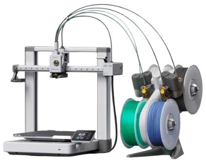
- Step 5: Printing the object and testing its movement. Importing the 3D Model (STL File)
- Layer height: Defines the thickness of each printed layer. A lower value results in better detail but increases print time.
- Line width: Controls the width of the printed lines, affecting strength and precision.
- Infill density: Determines how solid the print will be. A lower percentage makes it lighter, while a higher one makes it stronger.
- Support structures: If the model has overhangs, we may need to enable supports.
- Layer height: 0.2 mm
- Initial layer height: 0.2 mm
- Default: 0.42 mm
- Initial layer: 0.5 mm
- Outer wall: 0.42 mm
- Inner wall: 0.45 mm
- Top surface: 0.42 mm
- Sparse infill: 0.45 mm
- Internal solid infill: 0.42 mm
- Support: 0.42 mm
- Seam position: Aligned
- Smart seam application: Enabled
- Total filament used: 28.44 g (9.54 m)
- Estimated print time: 1 hour 4 minutes
- Filament type: Ensure that the selected filament matches the material loaded in the printer.
- Print bed leveling: The printer may perform an automatic leveling to ensure the first layer adheres correctly.
- Print time: The estimated duration of the print job is displayed.
- If the printed object has moving parts, gently test them to ensure they function correctly.
- Check for any friction points or areas that might need slight sanding or adjustments.
- If the movement is restricted, verify that no excess material (like stringing or over-extrusion) is causing interference.
- Square SolidWorks
Why I Use PLA for 3D Printing
I prefer to use PLA (Polylactic Acid) for 3D printing because it’s easy to work with and environmentally friendly. It's made from renewable resources like cornstarch or sugarcane, which makes it biodegradable and a better choice compared to other plastics. PLA also prints at lower temperatures (around 180-220°C), which reduces the risk of warping, and it works well with most 3D printers. I find it perfect for beginners like me, as it gives a smooth, high-quality finish. Plus, it’s odorless while printing and offers good strength for most small to medium-sized projects.
The first step in 3D printing is to obtain a 3D model in STL format. This file contains the shape of the object to be printed.
We open Bambu Studio, the software used to prepare the file for printing. Then, we load our STL file into the workspace by dragging and dropping it or using the "Open File" option.

Before we can print, we need to adjust some key parameters:
3D Printing Settings
For this print, I used a Bambu Lab A1 printer with a 0.4 mm nozzle and a Textured PEI Plate. The filament type was Generic PLA. Below are the detailed parameters used during slicing:
Layer Configuration
Line Widths
Seam Settings
Filament and Time
These settings were chosen to balance print quality and speed for the geometry of my design.
Once these settings are adjusted, we proceed to the next step.

After configuring the settings, we need to "slice" the model. This means converting the 3D object into a series of thin layers and generating a G-code file, which contains the instructions for the printer.
By clicking on "Slice Plate", Bambu Studio calculates how long the print will take, how much filament will be used, and how the printer will build the object layer by layer.
We can preview the sliced layers to ensure everything looks correct before sending the print job.

Once satisfied with the slicing, we send the file to the BambuLab A1. This can be done via a direct USB connection, SD card, or Wi-Fi if the printer supports it.
In this step, we also confirm important printer settings such as:
Once everything is checked, we click "Send" to start printing!

Step 5: Printing the Object and Testing Its Movement
The printer begins its process, heating the nozzle and bed, and then extruding the filament layer by layer. The progress can be monitored from the printer screen or the software.
After printing is complete, we allow the object to cool before carefully removing it from the build plate.
Once removed, we check the print for any defects, ensure all parts are properly formed, and remove any support structures if needed.
Testing the Movement:
And that's it! We've successfully printed and tested our 3D model using the BambuLab A1.
Documents
Design and Printing Advantages & Limitations
Advantages:
- Allows for complex geometries that are impossible to achieve with subtractive methods.
- Lightweight structure with high aesthetic appeal.
- No need for additional assembly since it is printed in one piece.
Limitations:
- Requires precise support structures to print correctly.
- Printing time is longer due to the intricate design.
- Potential for print failures if layer adhesion is not strong enough.
3D Scanning an Object
Additionally, we were also asked to 3D scan an object and optionally print it.
3D Scanning Technology
I used the Creality 3D scanner, which employs structured light technology. This scanner projects a pattern of light onto the object and captures distortions using a camera. By analyzing these distortions, the scanner reconstructs a precise 3D model.
Structured light scanning offers several benefits:
- High accuracy and detail in the scanned models.
- Fast scanning process compared to laser-based methods.
- Non-contact scanning ensures that delicate objects are not damaged.
However, it has some limitations:
- Difficulty in scanning reflective or transparent surfaces.
- Requires stable lighting conditions to work effectively.
- May need post-processing to clean up scan artifacts.
How to Use Creality Scan
What is Creality Scan?
Creality Scan is a 3D scanner developed by Creality, designed to capture high-precision 3D models. It is mainly used to digitize physical objects and convert them into 3D files for further editing or printing.
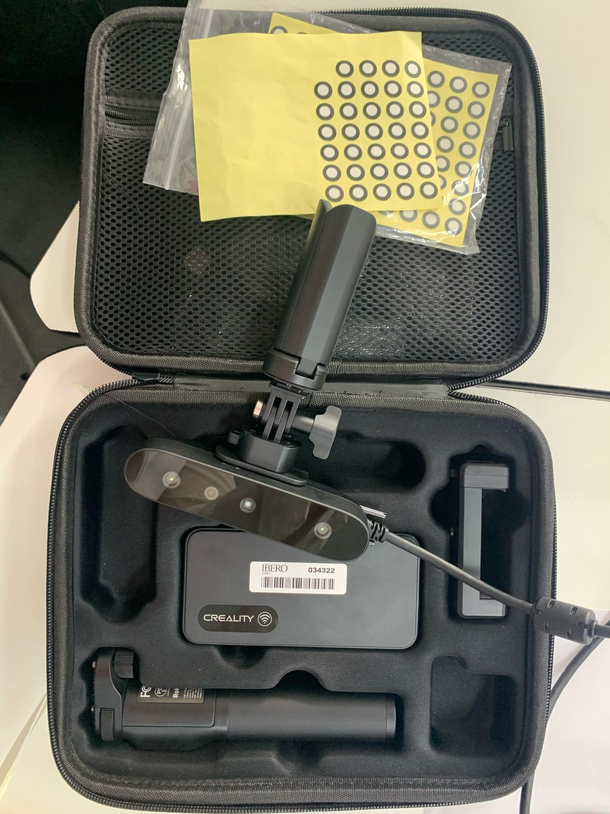
1. Software Installation
- Download the Creality Scan software from Creality's official website.
- Install the software following the setup instructions. Once you did that Open Creality Scan and select your scanner model.
- Connect the 3D scanner to your computer via the USB cable.

2. Scanner Setup
- Adjust the resolution and scanning parameters according to your needs.
- Place the object to be scanned on a stable surface.

3. Scanning Process
- Start scanning by pressing the "Start" button.
- Move the scanner around the object if necessary to capture all angles.
4. Exporting the Model
- Wait for the software to process the data and generate the 3D model.
- Review the model in the preview window.
- Save the file in STL format or your preferred format for 3D printing.
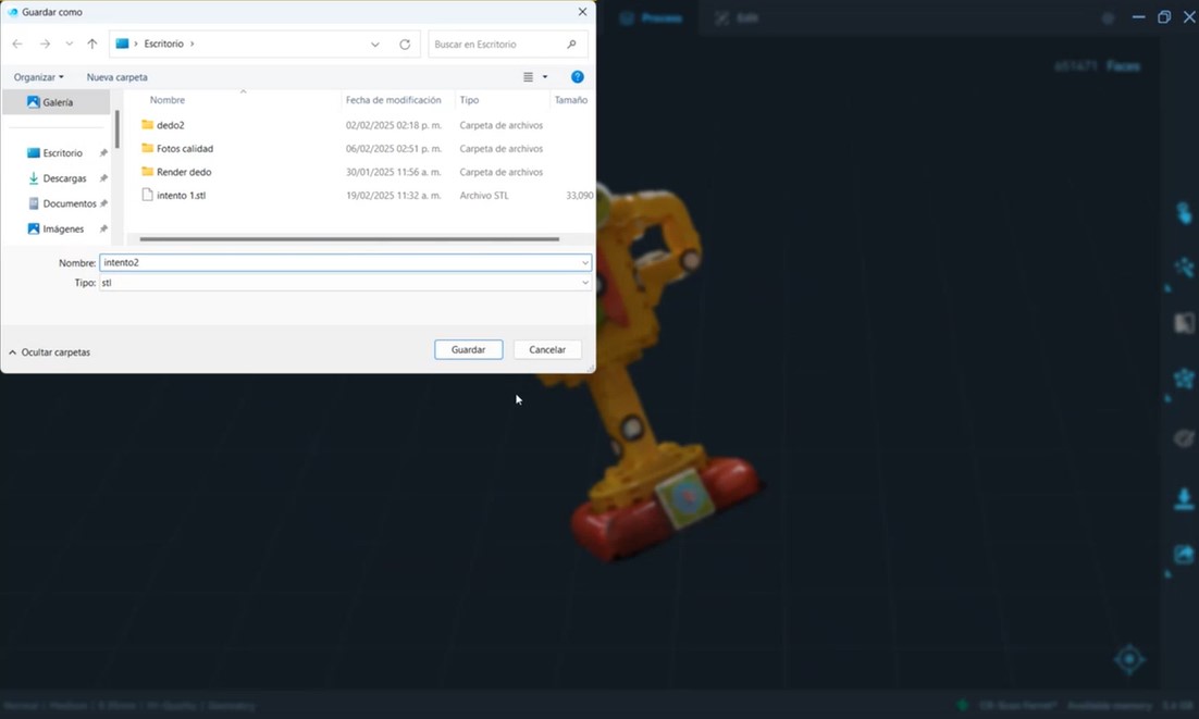
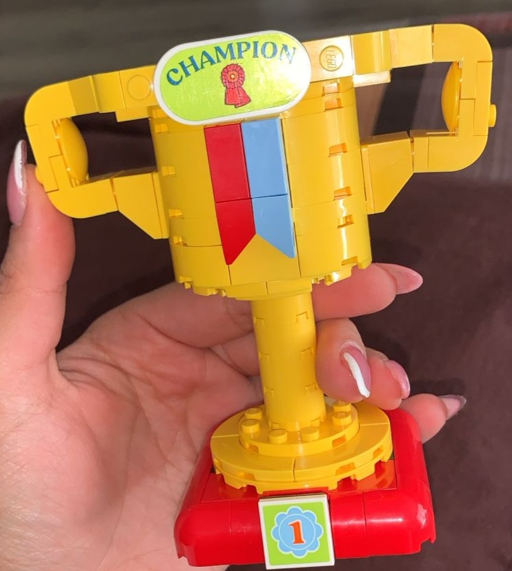
3D Scanned Model
Here is my scanned file. You can view it in 3D on Sketchfab:
Conclusion
This week at Fab Academy was both creative and hands-on. I learned how to 3D scan and print, exploring possibilities beyond traditional manufacturing methods.
For 3D printing, I designed an object in SolidWorks that couldn't be made subtractively: a series of floating frames rotating on the same axis. I went through the entire process, from modeling to printing on my BambuLab A1, ensuring proper tolerances for smooth movement.
I also experimented with 3D scanning using Creality Scan, capturing a physical object and turning it into a digital model. It was fascinating to see how technology can recreate shapes with great precision.
Overall, it was an intense but awesome week. I gained valuable insights into the limits and possibilities of 3D in digital fabrication. Excited for what’s next!
