Computer-Controlled Cutting
For this week's assignment in Fab Academy, we focused on designing a parametric kit for laser cutting and exploring the use of a vinyl cutter. Parametric design allows for flexible and easily adjustable models, making fabrication more efficient and adaptable. By using laser cutting, we can create precise interlocking pieces, while the vinyl cutter enables the production of detailed graphics, stickers, or flexible circuits.
Parametric Kit for Laser Cutting
First of all, what does it mean for a kit to be parametric? A parametric kit is a set of pieces designed to adapt to different sizes and configurations without the need to redesign from scratch. This means that dimensions, shapes, and functions depend on user-defined variables.
With the knowledge acquired in Week 2 of Computer-Aided Design, we will design our parametric kit. We will use SolidWorks software, and to make it parametric, we will use the Equations tool. This tool allows us to establish mathematical relationships between model dimensions. Basically, you define a rule, and the software updates the design automatically.
For example, if a piece must always be twice as wide as another, you can write an equation like Length = 2 * Width, so any change in width will automatically update the length, optimizing the design process and reducing errors.
How to Use Equations in SolidWorks
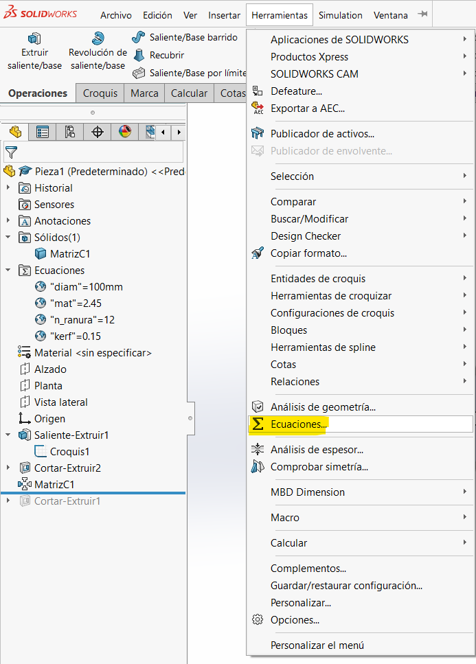
In SolidWorks, the Equations tool is found in the functions menu. To access this function:
- Open SolidWorks and create a new part.
- Go to the top bar and click on Tools.
- Select Equations... from the dropdown menu.
Designing My Parametric Kit
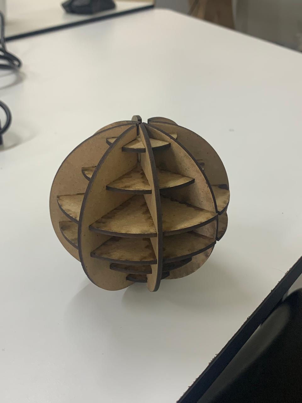
For my parametric kit, I decided to create a sphere that can transform into different shapes. To do this, I need six circles:
- Two with a diameter of 100mm
- Two with a diameter of 70mm
- Two with a diameter of 40mm
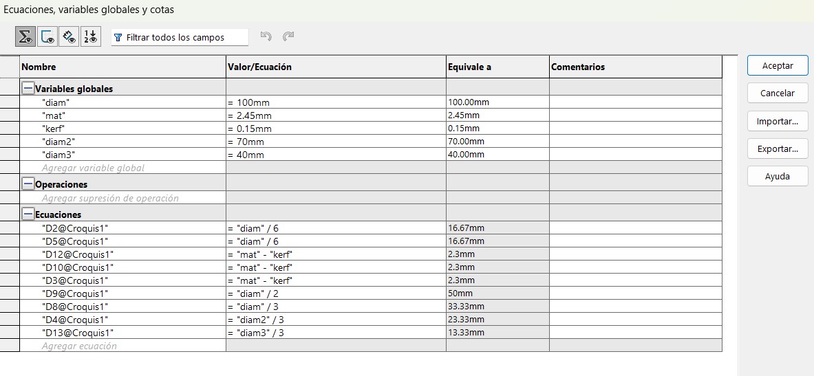
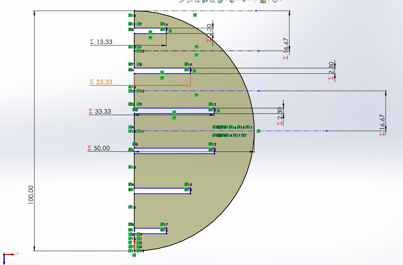
All six will have slots to assemble the tabs. We start by entering the equations for my measurements.
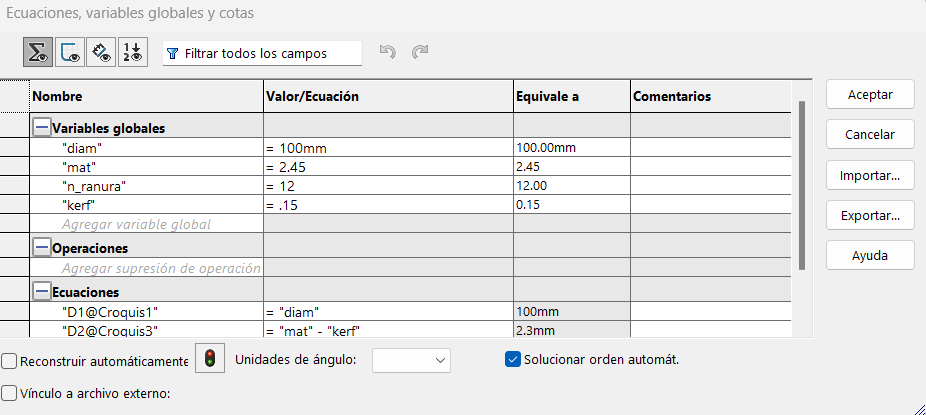
Where:
- diam = circle diameter
- mat = material thickness
- n_slot = number of slots
- kerf = material extra cut by the laser cutter (Specify the cutter model)
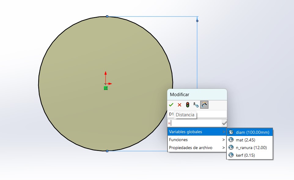
Drawing the Circle
Creating the Slots
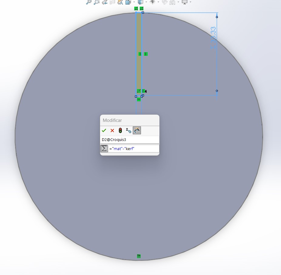
Once we have the circle defined by our equation, we create a new sketch and draw a rectangle. The length of the rectangle will be diameter / 3 to ensure that when the diameter changes, the parameters update automatically.
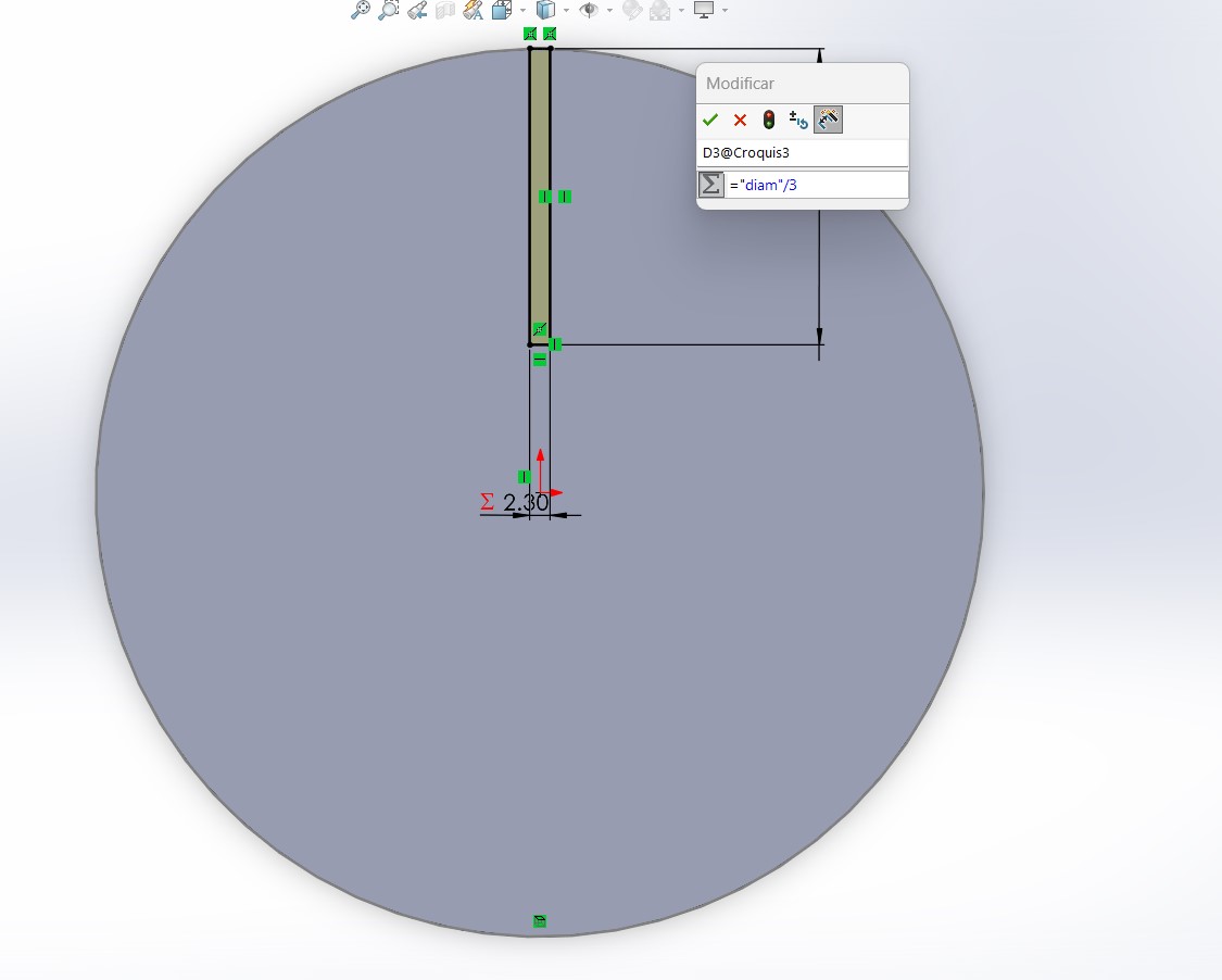
For the width, we use mat - kerf, where mat is the material thickness and kerf is the laser cut width.
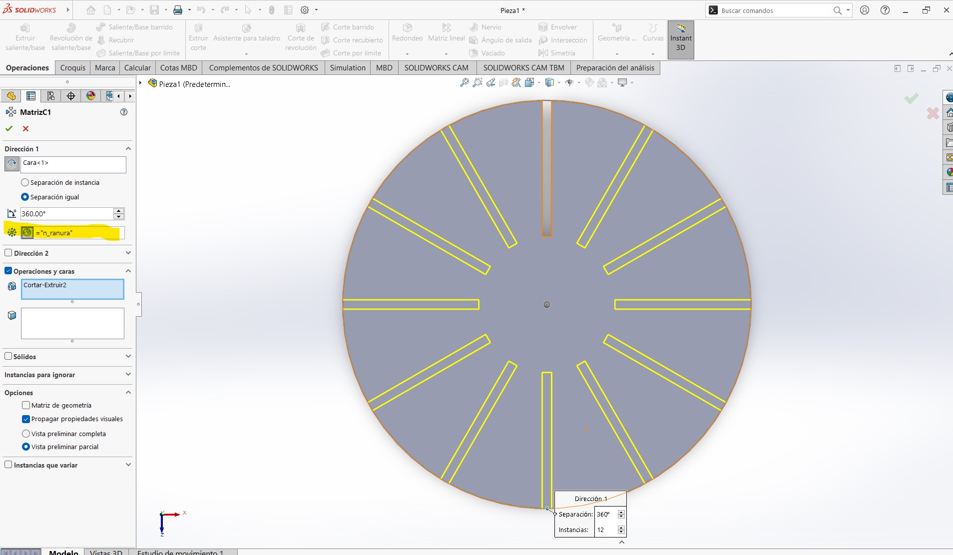
Creating Multiple Slots
Using the Linear Pattern tool, we select the Circular Pattern option. In the left menu, where the number of openings is specified, we input =n_slot, which we previously set to 12 in our equations.
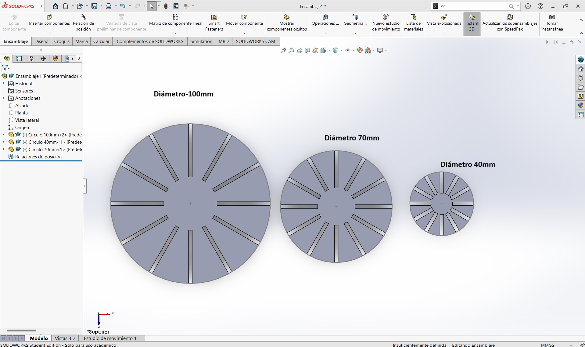
Finalizing the Design
This completes the base for our sphere. For other sizes, we simply change the values in the equations.
Saving and Exporting for Laser Cutting
To prepare our files for cutting, they must be saved in .DXF format.
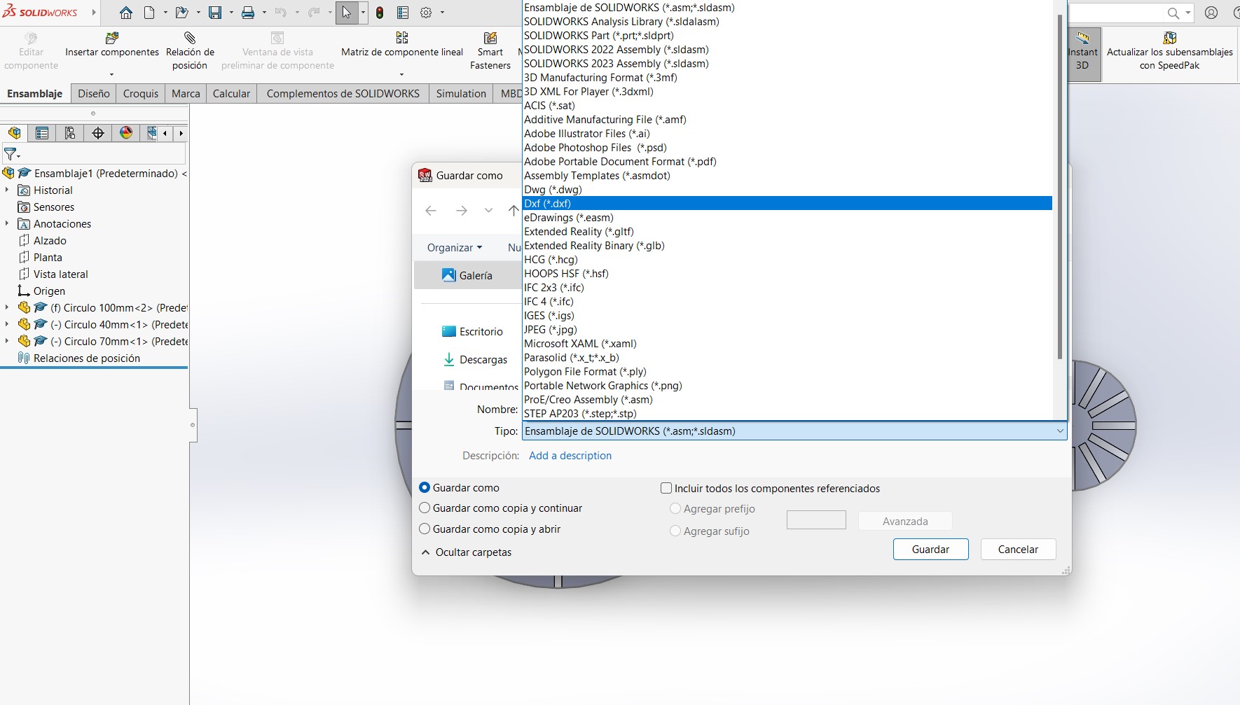
Once in DXF format, the file should look like this:

Now, we will create the connection part. For the piece that will join our circles, we follow the same process: we add the values in the equations and design the piece with the appropriate slots for the 6 circles. Each slot has a diameter equivalent to the circle divided by 3, and this is configured in our equations. Meanwhile, the width of these slots follows the same Kerf operation.
- Parametric kit
Documents
How to use the Laser Cutter
To use the laser cutter, it is essential to understand safety measures and cutting parameters such as power, speed, rate, kerf, joint clearance, and joint types. As we covered in the group assignment, we learned how to operate the laser cutter and the key parameters to consider when cutting our material.
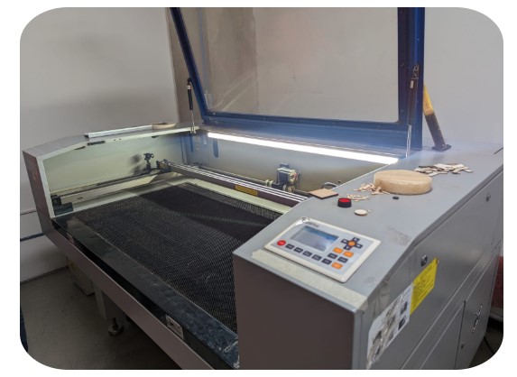
Using the CAMFive CFL-CMA1080K Laser Cutter with Smart Carve 43
In our laboratory, we have the CAMFive CFL-CMA1080K laser cutter, and the software used to adjust cutting and engraving parameters is Smart Carve 43. Below are the steps to use it:
Steps to Use Smart Carve 43
Download SmartCarve 4.3
Click the link below to go to the SmartCarve 4.3 download page:
Go to Download- Open the Software
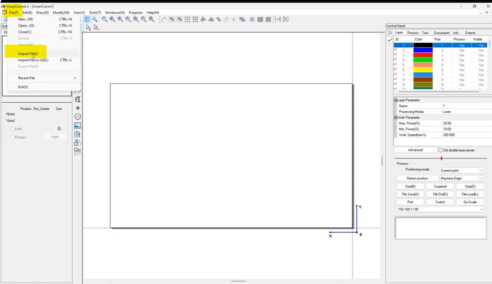
- Launch Smart Carve 43 on your computer.
- Import the Design File
- Select the "Open" or "Import" option from the menu.
- Navigate to your file's location and open it.
- Compatible formats: SVG, DXF, AI, BMP, and others.
- Turn on the cooling system and make sure it has enough water.
- Place the material flat on the cutting bed.
- Turn on the laser cutter and set the origin point where the cut will start.
- Ensure the material is secured and aligned properly on the cutting bed.
- The CMA1390 uses a metal focus gauge to set the correct distance.
- Place the focus gauge between the laser head and the material.
- Adjust the cutting bed height using the up/down arrows on the control panel until the gauge barely touches the nozzle.
- Once aligned, remove the focus gauge.
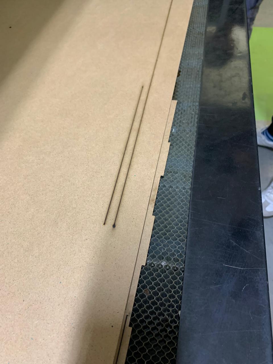
- Run a low-power test cut on the material.
- Observe the cut quality:
- If the cut is sharp and clean, the focus is correct.
- If the cut is blurry or incomplete, repeat the focusing process.
- Use the control panel to configure the power and speed settings based on the material type.
- Confirm the settings before starting the final cut.
- Set Cutting Parameters
- Adjust the values based on the material:
- Power: Laser power
- Speed: Cutting speed
- Adjust the values based on the material:
- Adjust the Design in the Work Area
- Use Smart Carve 43 tools to move, rotate, and resize the design within the cutting area. Then save it as an OUD in your usb device
- Safety Guidelines
- Wear appropriate protective gear if necessary.
- Ensure proper ventilation in the workspace.
- Do not leave the machine unattended while it is operating.
Focusing the Laser Cutter (CMA1390)
To achieve precise cuts, it's essential to correctly focus the laser. The CAM-Five CMA1390 laser cutter at FabLab Puebla uses a manual focusing method with a focus gauge. Here's the step-by-step process I followed:
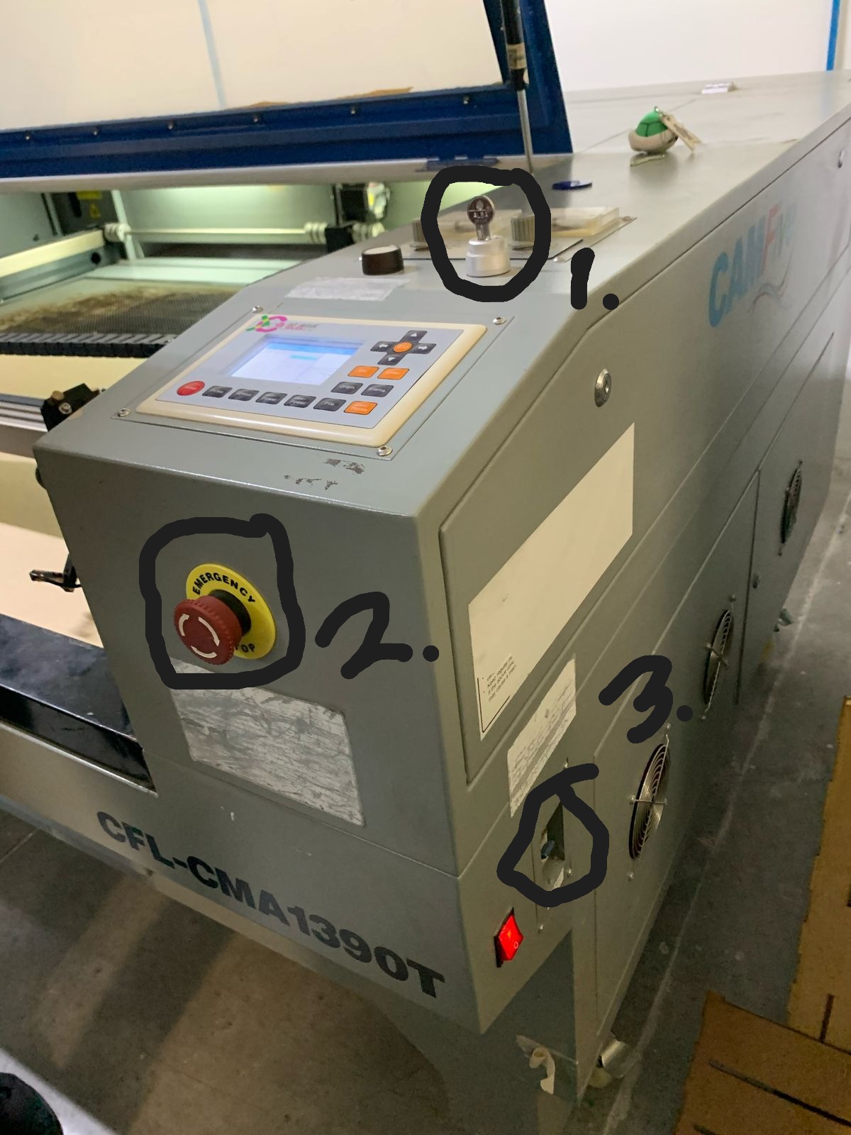
1. Preparing the Machine
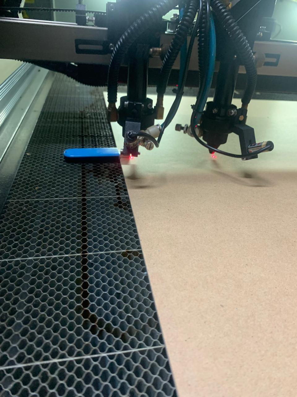
2. Positioning the Material and Adjusting the Focus
3. Performing a Test Cut
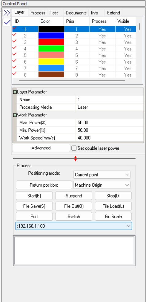
4. Setting Up the Control Panel
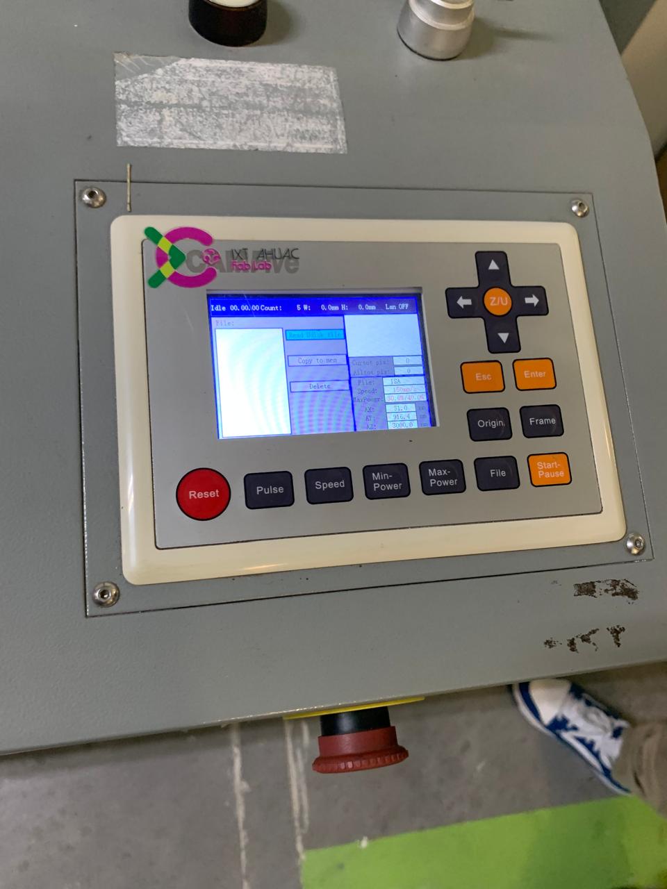
How to Use the Laser Cutter
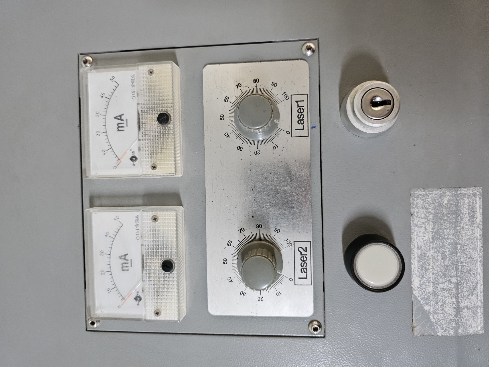
- First, insert the master key to turn on the machine, then remove the safety lock, and finally switch on the power. This means the machine is now on.
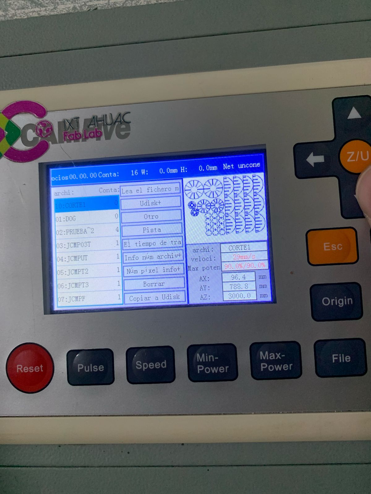
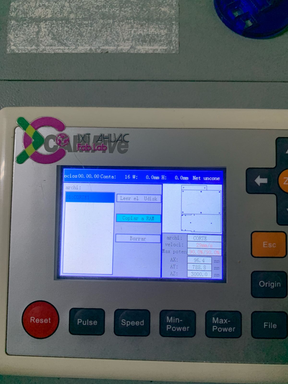
- Insert your USB drive, select the Udisk+ option, find your file, and choose the option to copy it to RAM.
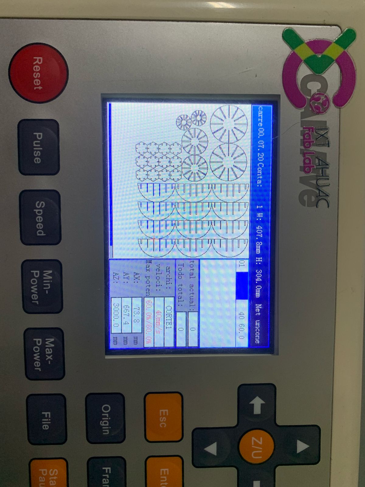
- Now, visualize your file. It already includes the cutting and origin specifications set in the Smart Carve program.
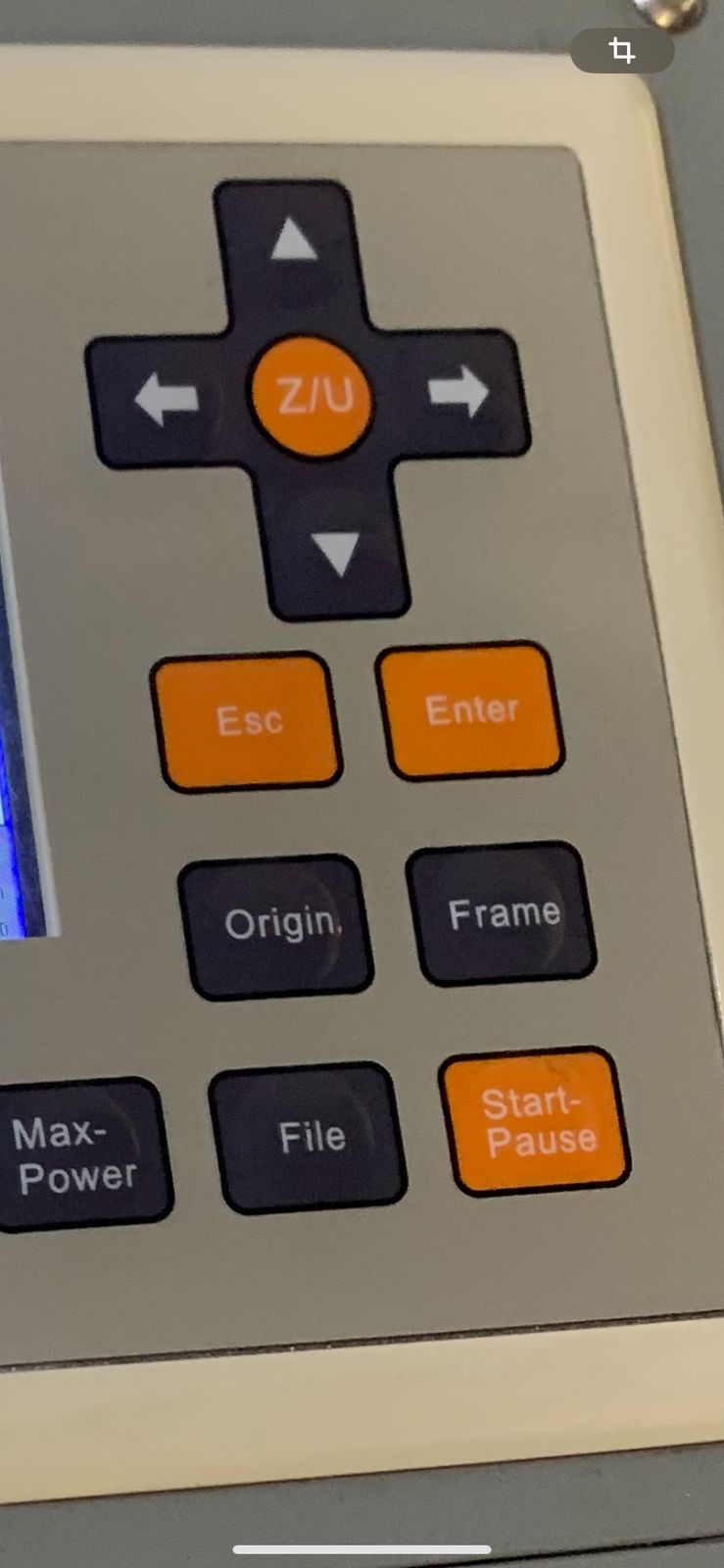
- Place your material on the cutting bed and press the Origin button on the console. This will show where the cutting will start.
- The laser is invisible, so it is crucial not to put your head, hands, or any part of your body inside once the machine is on.
- The machine has two lasers. To use one or the other, you must set the laser you will use to 100% power.Once you confirm the origin is correct, press the Frame button to check the cutting area. Turn on the laser with the white button—at this point, you must not put your hands inside. Close the machine and press Start.
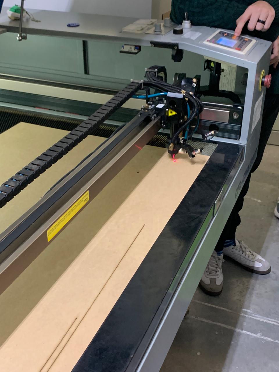
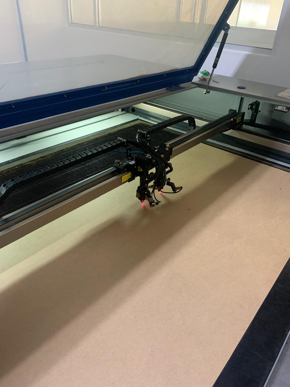
Laser Cutter in Action
Here is the laser cutter cutting the pieces.
Assembling Our Parametric Kit
Now it's time to assemble our parametric kit.
Creations with the Parametric Kit
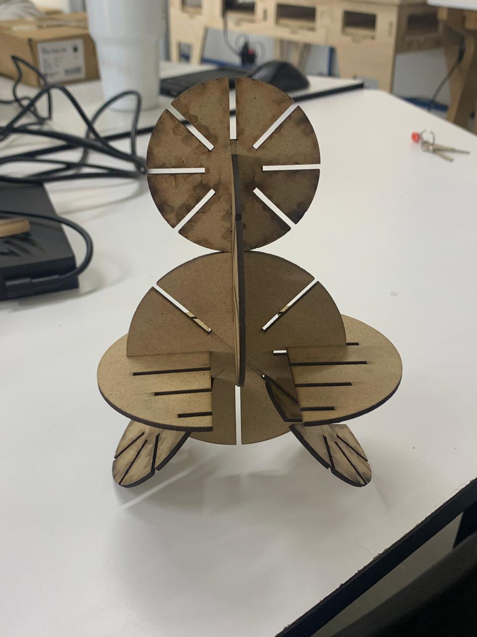
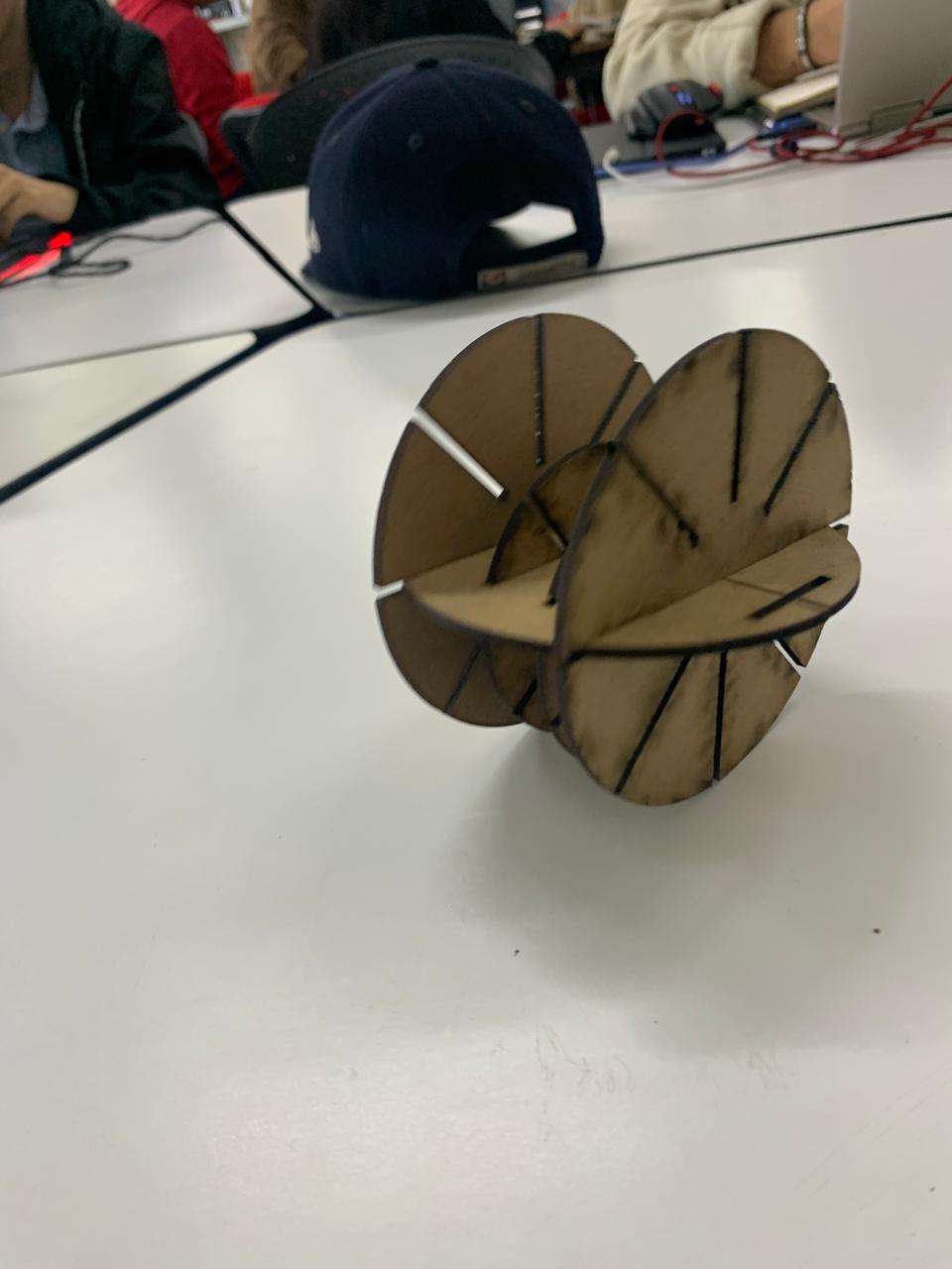
Here are some figures that can be made with the parametric kit:
- A Toy
- A Sphere
- Various wheels of different sizes
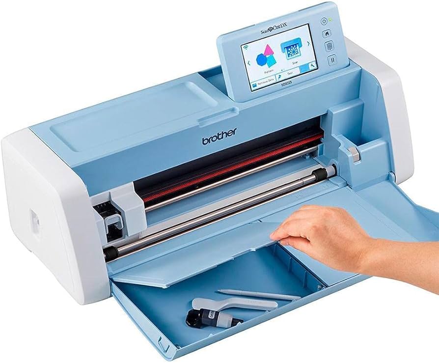
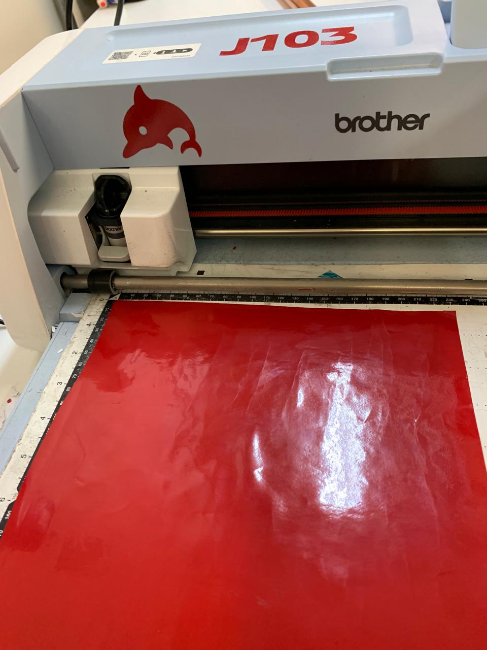
How to Use the Brother SDX225 Vinyl Cutter with an SVG File
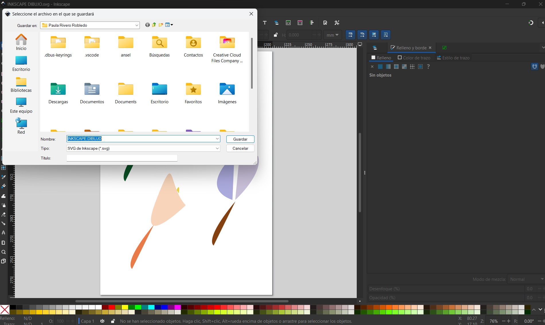
For the Vinyl Cutter I used the design I made during week 2 in Inkscape, if you want to know more about computer design , check out week 2. Here is the file of Inskape .
Flowers in Inkscape
- Prepare Your SVG File: Make sure your design is in SVG format, I used the design I did in Inscape on week 2.
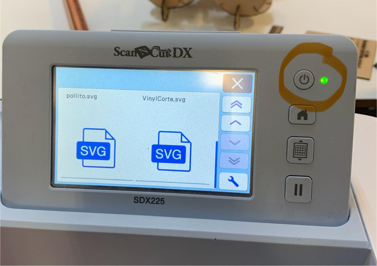
- Turn On the Machine: Press the power button to turn on the Brother SDX225.
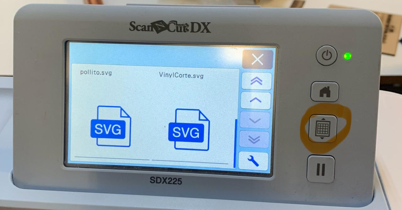
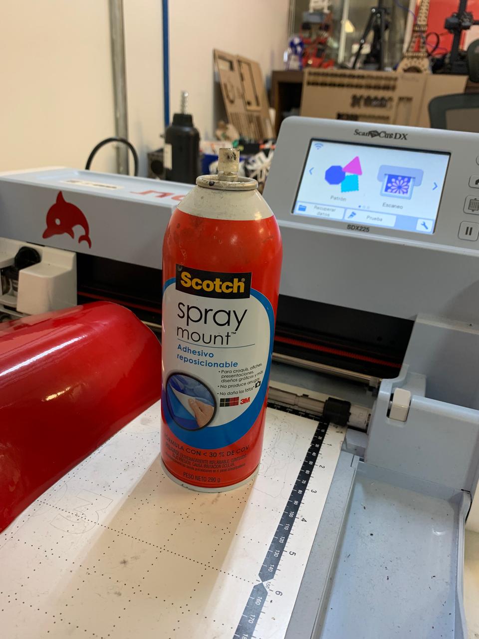
- Load the Vinyl: Place the vinyl sheet on the cutting mat with an Adhesive Spray and load it into the machine by pressing the Load Mat button.
- Import the SVG File:
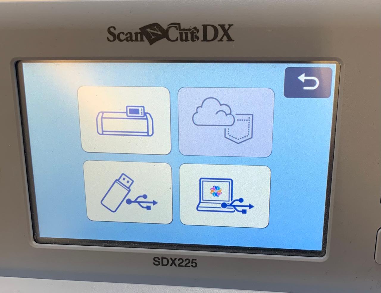
- Insert a USB drive containing your SVG file, or use a wireless connection if available.
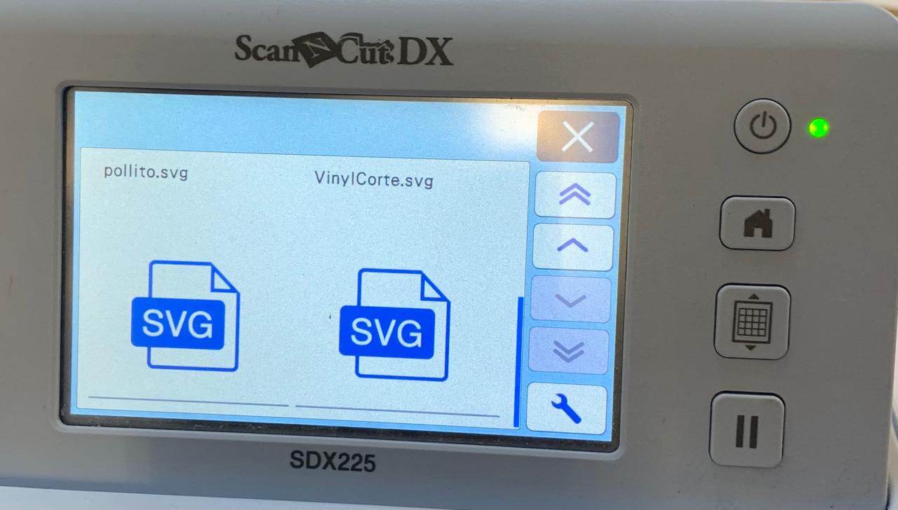
- On the machine's touchscreen, go to Retrieve Data and select your file from the USB or cloud storage.
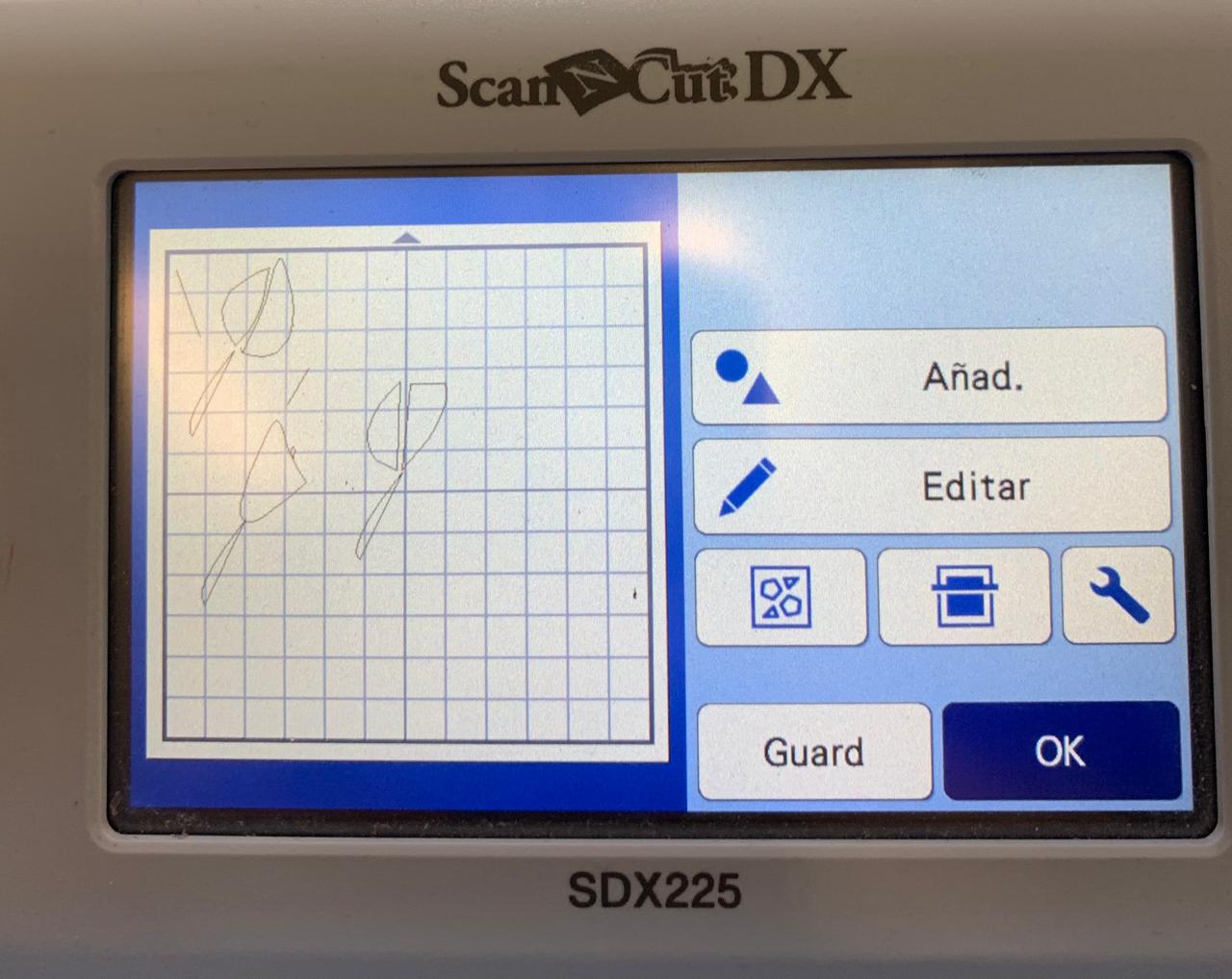
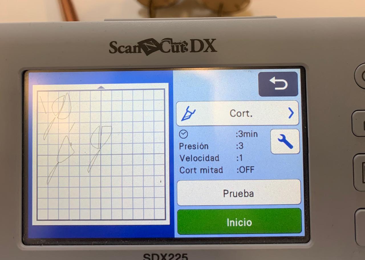
- Adjust the Cut Settings:
- Set the blade depth, pressure, and speed according to the type of vinyl.
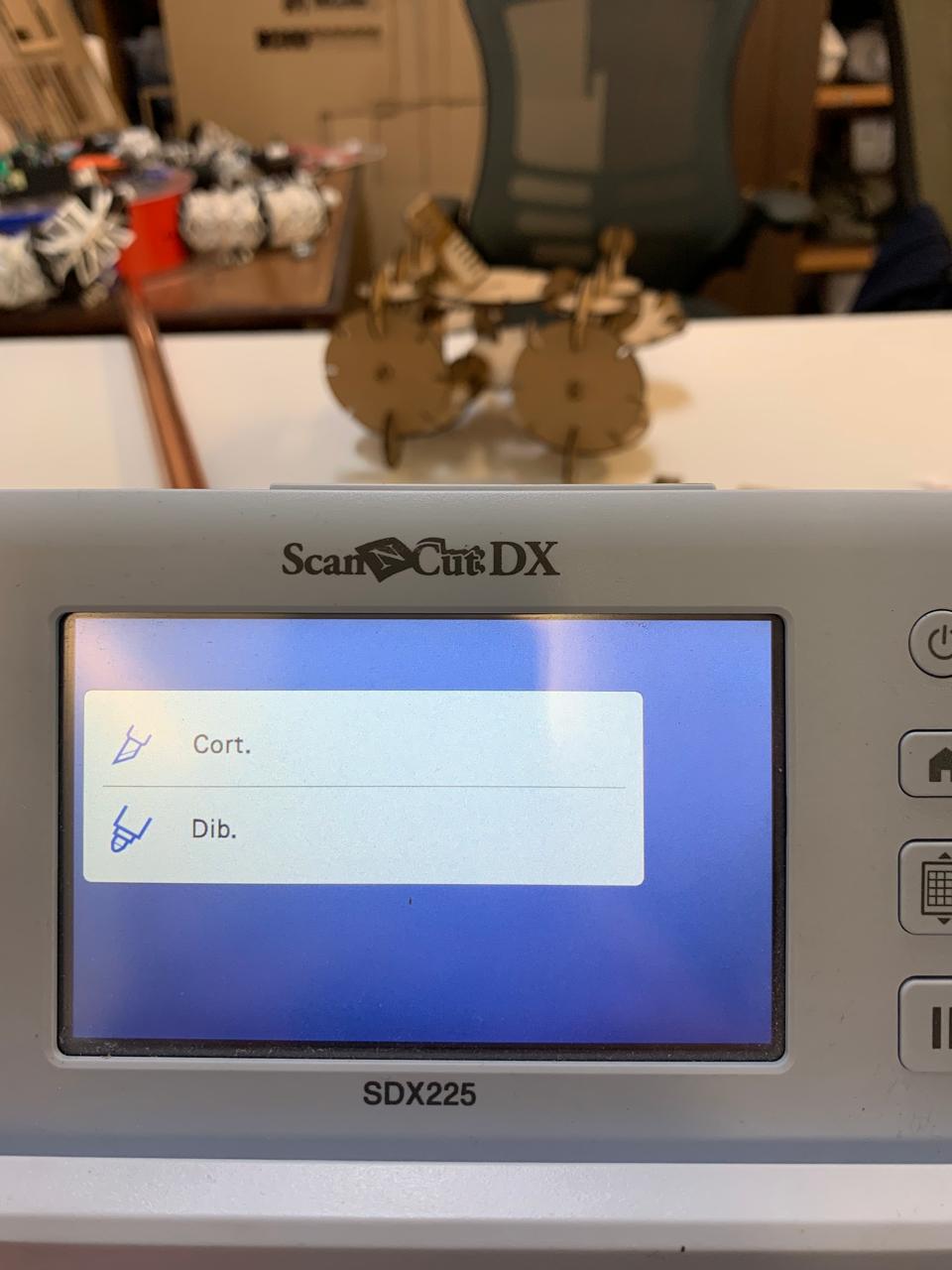
- Start Cutting: Once settings are correct, press Start to begin cutting.
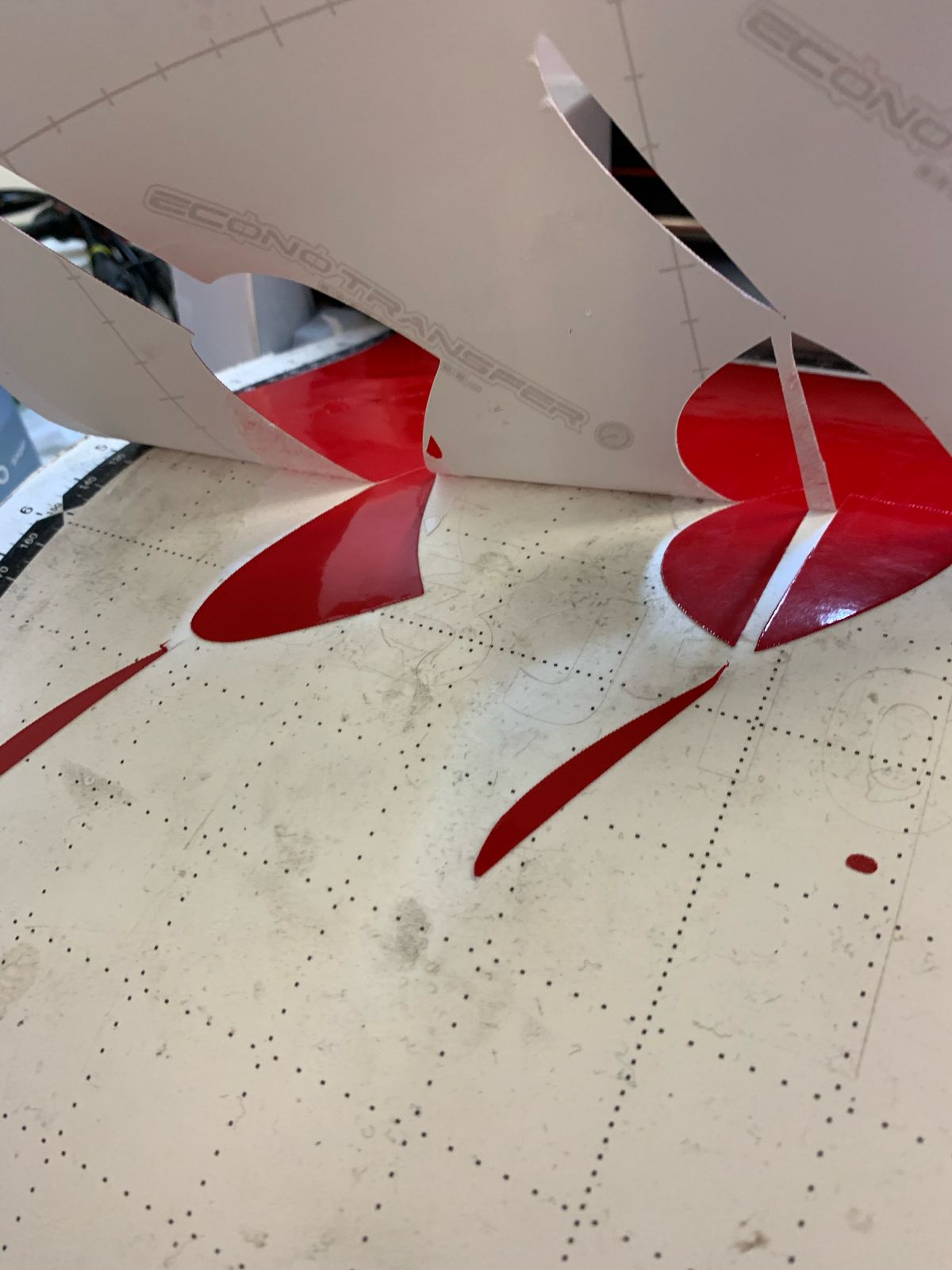
- Unload and Weed: After cutting is complete, unload the vinyl and carefully remove excess material (weeding).
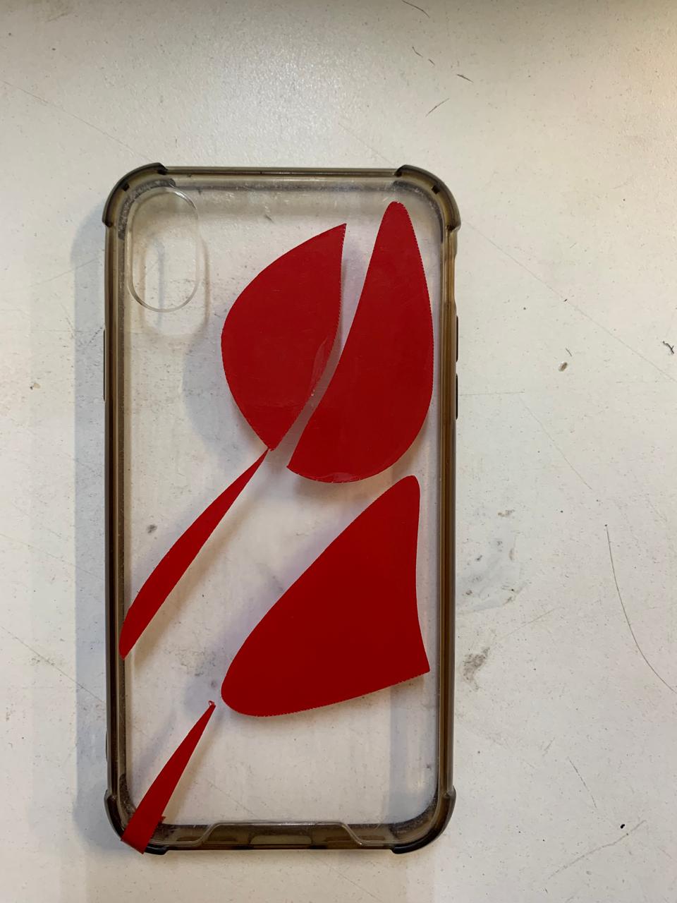
- Apply Transfer Tape: Place transfer tape over your design for easy application to the desired surface.
Laser Cutting and Vinyl Cutting Experience
This week, we learned how to use the laser cutter and the vinyl cutter. The laser cutter is a very powerful and dangerous machine if not used correctly, but it allows us to work with different materials to create various things, from simple prototypes and decorations to games and much more.
Using the laser cutter was an interesting experience, and assembling the parametric kit made the process much easier.
For the vinyl cutter, I used the design I created in Inkscape during week 2. Even so, it was a new experience for me since I had never used a vinyl cutter before. Especially in terms of design, this opens up a world of possibilities, allowing us to create everything from logos to stickers.
- © Copyright 2025 [Paula Rivero Robledo]
- Creative Commons Attribution Non Commercial