Computer-Aided Design
For the second week of Fab Academy, we explored various Computer-Aided Design (CAD) tools to model a possible final project. CAD software allows us to create digital representations of objects in 2D and 3D, helping to visualize and refine designs before fabrication.
Types of Computer-Aided Design
There are different approaches to CAD modeling, each serving specific purposes:
- 2D Design: Used for sketches, schematics, and technical drawings. Common formats include raster and vector graphics.
- 3D Modeling: Allows the creation of three-dimensional objects, useful for prototyping and manufacturing.
- Rendering & Animation: Enhances models with realistic textures, lighting, and movement.
- Simulation: Tests the behavior of a design under real-world conditions before production.
Software Tools
During this assignment, I experimented with different software for 2D and 3D modeling, comparing their features and usability.
Below, I present the design files and models created during this week.
Comparison: Inkscape vs. Adobe Illustrator
For 2D vector design, two popular tools are Inkscape and Adobe Illustrator. Below is a comparison of their features:
| Feature | Inkscape | Adobe Illustrator |
|---|---|---|
| Price | Free and open-source | Paid (subscription-based) |
| Platform | Windows, macOS, Linux (also available online) | Windows, macOS |
| File Compatibility | Supports SVG, PNG, PDF, EPS | Supports AI, SVG, PDF, EPS, and more |
| Best For | Beginners and open-source enthusiasts | Professional designers and businesses |
Download Links
- Download Inkscape (Free)
- Download Adobe Illustrator (Paid)
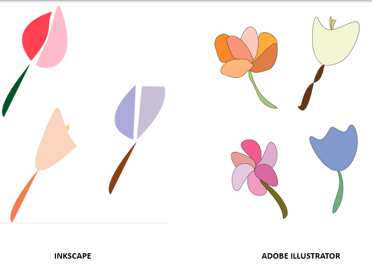
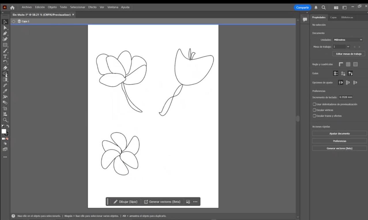
Image Comparison
Here is the two drawings I made in the differnet platforms of 2D Design
And Here are the files of each Drawing:
Vectorizing with Adobe Illustrator
Vectorizing in drawing means converting a raster image (made of pixels) into a vector image (made of mathematical lines and curves).
Why vectorize a Drawing?
- Allows scaling without losing quality.
- Makes editing and modifying shapes easier.
- Ideal for logos, illustrations, and graphic design.
There are two Tools for Vectorization
- Automatic: Inkscape, Adobe Illustrator (with "Image Trace" tool).
- Manual: Drawing with the "Pen Tool" in design software.
For this Assignment I decided to do the vetorization Manually, so let's start Manual Vectorization with Adobe illustrator
How to Vectorize a Drawing in Adobe Illustrator
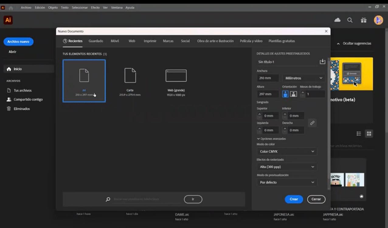
Step 1: Open Adobe Illustrator and Select Your Canvas Size
The first step is to open Adobe Illustrator and choose the size of the canvas you will use to start your design.
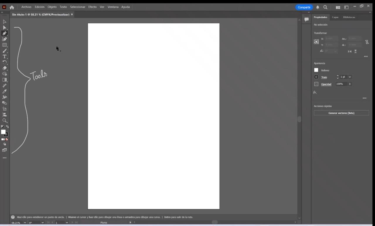
Step 2: Understanding the Interface
Once you've chosen the canvas size, your screen will look like this. On the left side, you'll find the tool menu, which offers various options from vectorization to gradient effects. An interesting fact: Adobe Illustrator allows you to vectorize using Artificial Intelligence, making it ideal if you need creative inspiration.
Step 3: Selecting the Pen Tool
To start vectorizing, select the "Pen Tool." There are two types:
- One for drawing straight lines
- One for creating curves
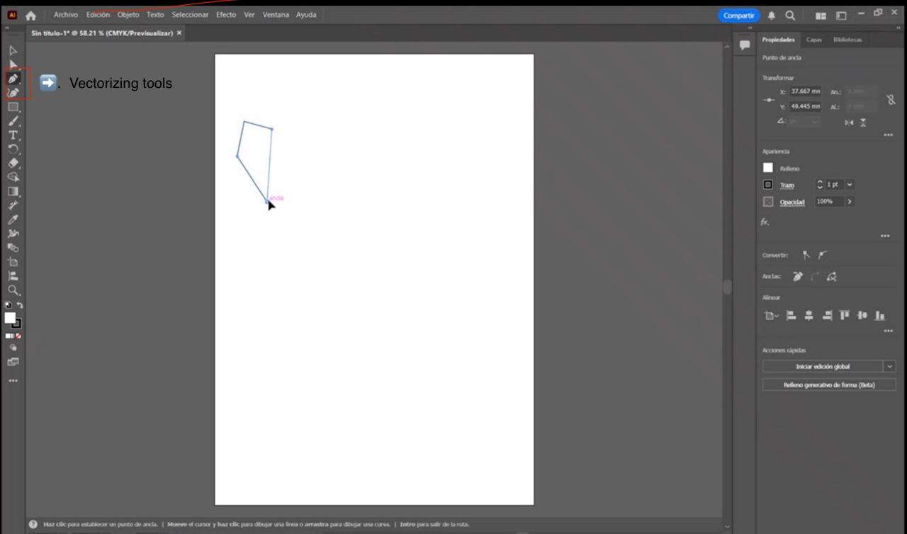
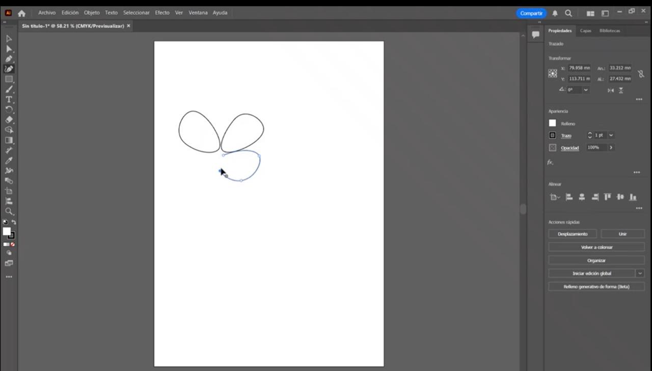
Step 4: Start Drawing
Select the pen tool that suits your design needs. In this case, I used the curved pen tool to draw flowers.
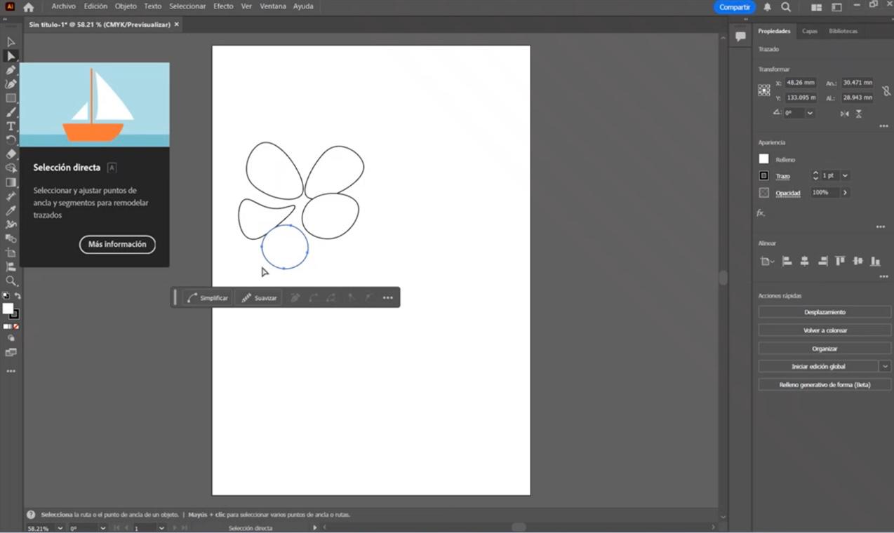
Step 5: Editing Your Drawing
On the left side, you’ll find the "Direct Selection" tool. Click it and double-click your drawing to edit it. You can change its shape, make it wider or taller, and adjust the curvature.
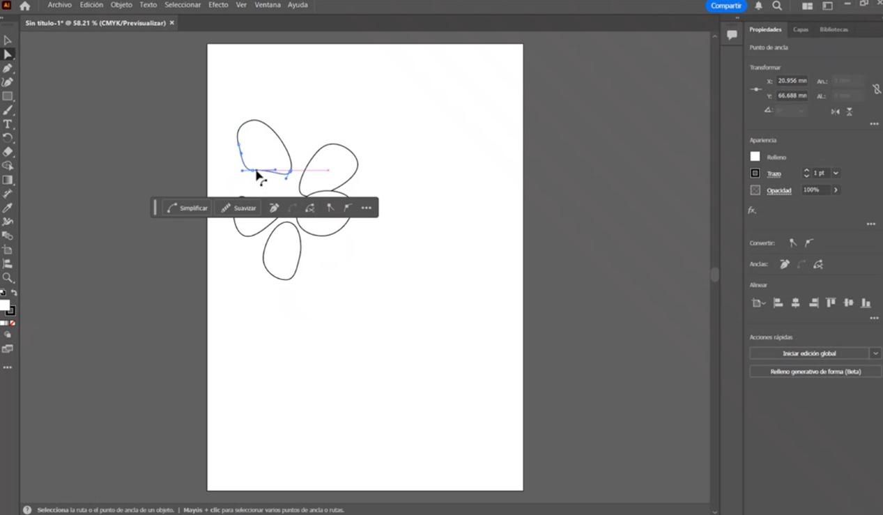
Step 6: Adjusting Curves
The blue anchor points help you modify your drawing in the desired way.
Step 7: Moving and Transforming Your Design
On the left-side menu, the first tool is an unfilled arrow. This allows you to move, rotate, or scale your design proportionally.
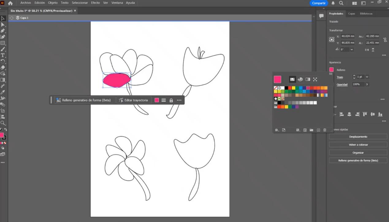
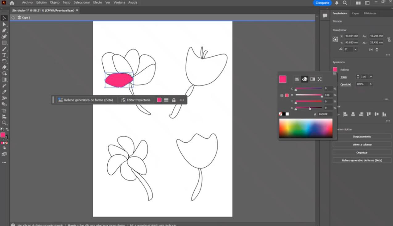
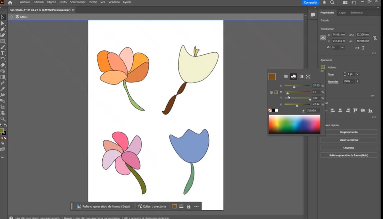
Step 8: Adding Color
To add color, simply select the part of the drawing you want to paint. On the right side, you'll find the "Fill" tool. This tool displays a preset color menu, but you can access more shades by clicking on the "Color Palette" icon.
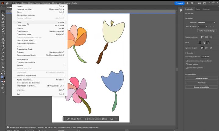
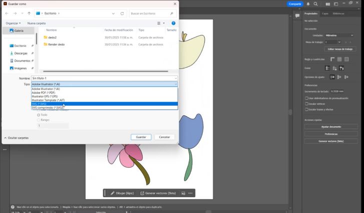
Step 9: Saving Your Vectorized Drawing
Once you’ve finished adding colors, it’s time to save your vectorized drawing. Go to the top menu and select "File" → "Save As", then choose the ".SVG" format. And that’s it! Your vectorized design is ready.
Conclusion
Adobe Illustrator is a very user-friendly platform. Once you understand the basic tools, creativity has no limits. Its intuitive interface provides explanations for each tool, making it easy for beginners to learn.
How to Vectorize a Drawing in Inkscape
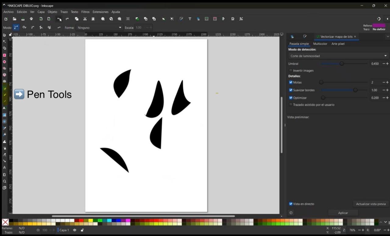
Step 1: Selecting the Pen Tool
To start vectorizing in Inkscape, select the "Pen Tool" from the left toolbar. This tool allows you to create both straight lines and curves.
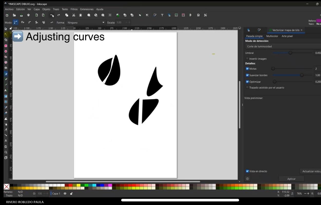
Step 2: Adjusting Curves
After drawing a shape, you can modify its curves using the "Edit Paths by Nodes" tool. By selecting a node, you can adjust its handles to refine the shape of your design.
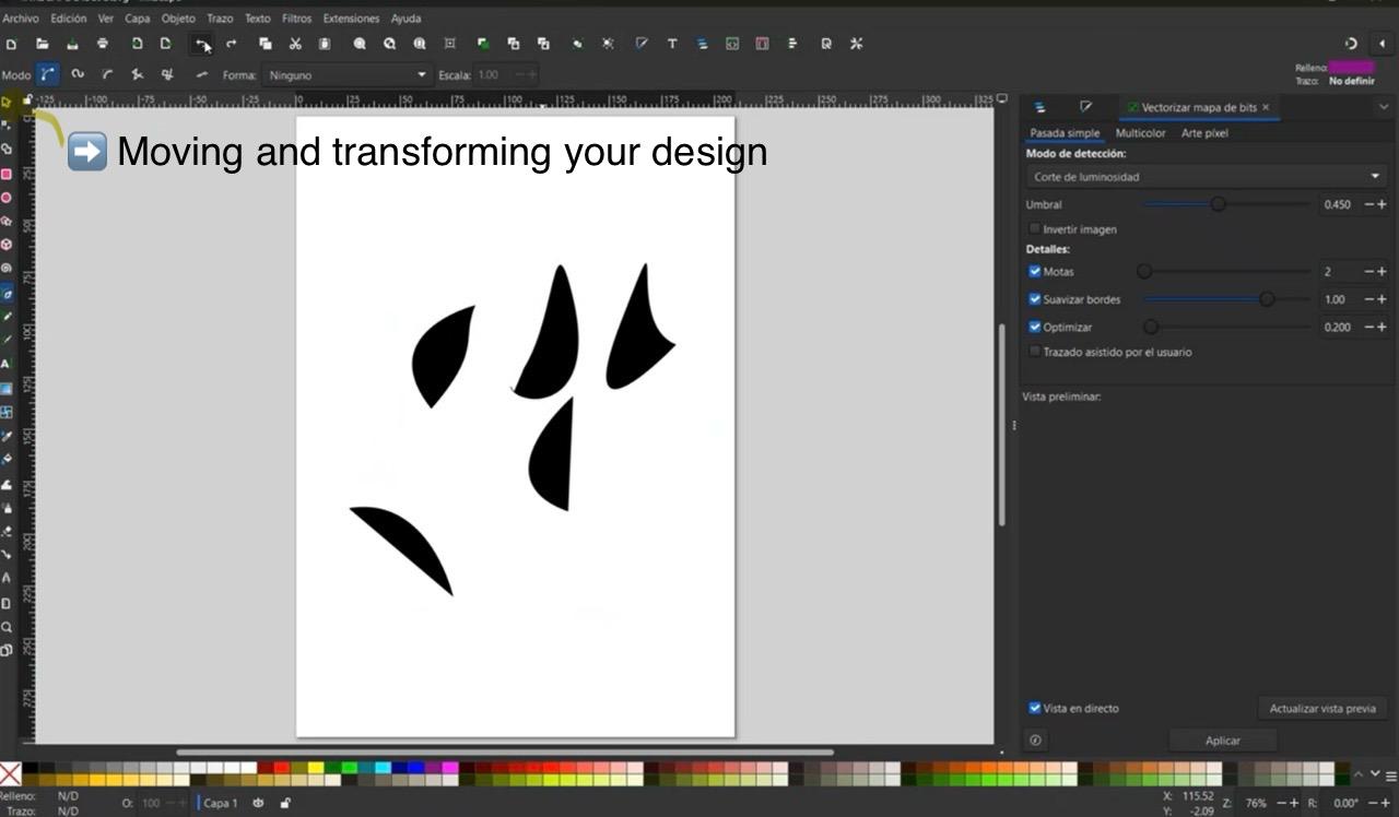
Step 3: Moving and Transforming Your Design
To move, rotate, or scale your design, use the "Select Tool" (black arrow) from the left toolbar. This tool allows you to manipulate objects freely while maintaining proportions.
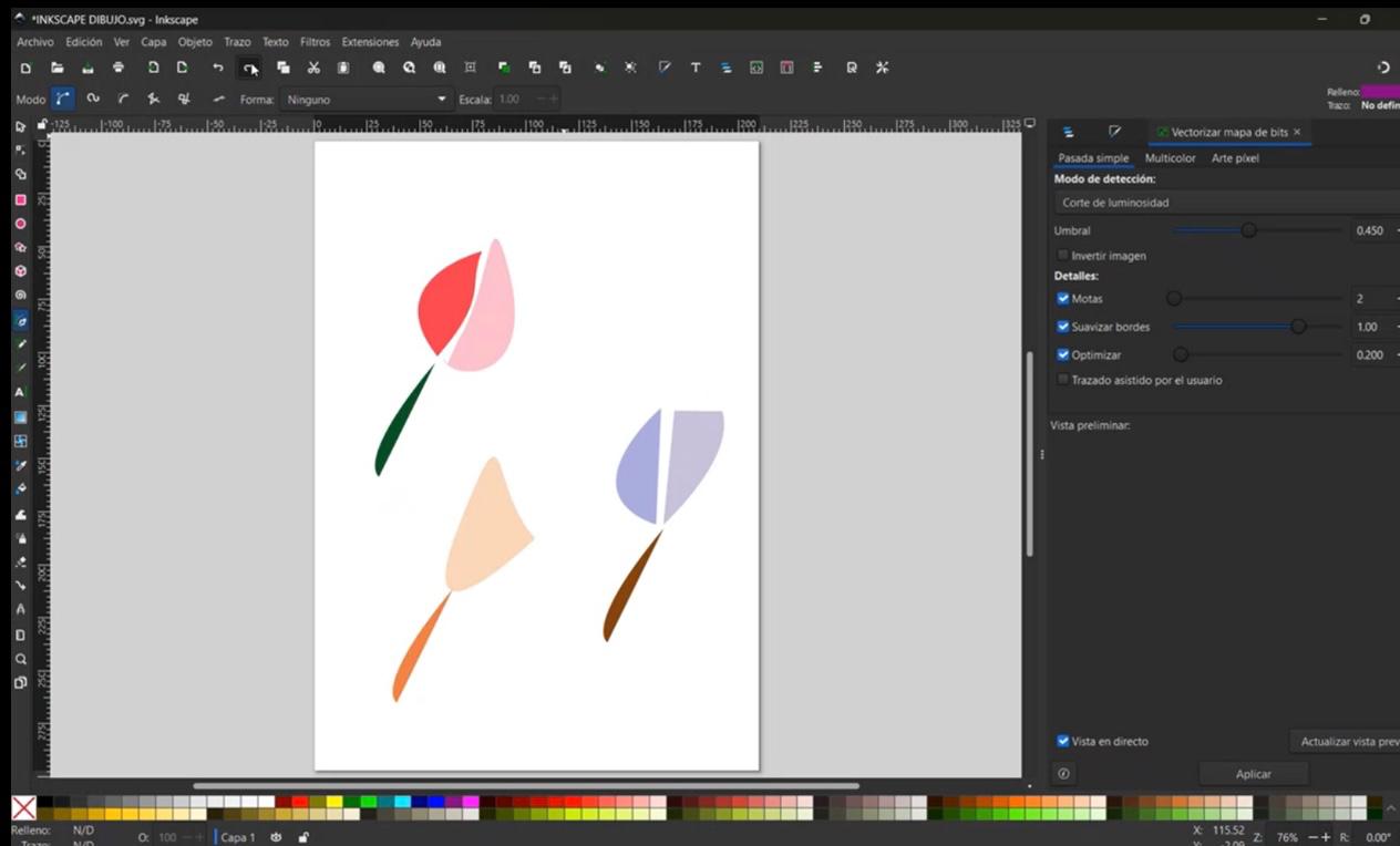
Step 4: Adding Color
To add color to your drawing, select the object and use the "Fill and Stroke" panel on the right side. Here, you can choose a solid color or apply gradients for more complex effects.
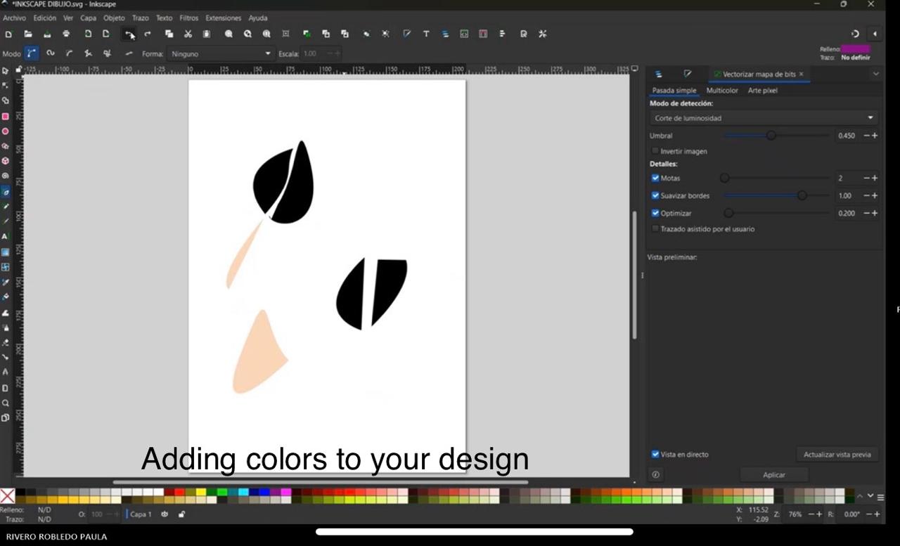
Conclusion
Inkscape is a powerful and free vector design tool. It provides many of the same features as Adobe Illustrator, making it a great option for designers looking for an accessible yet professional-grade software. With a bit of practice, you can create stunning vector illustrations with ease.
SolidWorks vs. Fusion 360
When it comes to 3D modeling and CAD software, SolidWorks and Fusion 360 are two of the most popular options. Both are excellent for designing mechanical parts, prototypes, and assemblies, but they have key differences.
What is SolidWorks?
SolidWorks is a powerful 3D CAD software widely used in engineering and industrial design. It offers advanced features for parametric modeling, simulation, and manufacturing.
Price: Paid (requires a license)
Download: SolidWorks Official Site
What is Fusion 360?
Fusion 360 is a cloud-based CAD software developed by Autodesk. It integrates modeling, simulation, and CAM (computer-aided manufacturing) in a single platform.
Price: Free for students and startups
Download: Fusion 360 Official Site
Comparison Table
| Feature | SolidWorks | Fusion 360 |
|---|---|---|
| Cost | Paid (expensive, requires a license) | Free for students |
| Accessibility | Requires installation on Windows | Works online and on multiple devices |
| Best For | Professional engineering and industrial design | Beginners, startups, and makers |
| User Interface | More complex, requires training | More intuitive and easier to learn |
How to Design in SolidWorks
To use SolidWorks effectively, it is essential to understand some basic commands. Below, I will introduce a few key commands, but if you want to learn more, you can explore an extensive guide with additional tools and commands here: SolidWorks Command Guide
Basic Commands in SolidWorks
1. Sketching Tools
SolidWorks allows you to create 2D sketches, which serve as the foundation for 3D models. Some essential sketching tools include:
- Line: Draws straight lines.
- Rectangle: Creates rectangular shapes.
- Circle: Generates circular sketches.
- Smart Dimension: Adds precise measurements to your sketch.
2. Extrude and Revolve
Once you have a sketch, you can convert it into a 3D object using:
- Extrude: Extends a 2D shape into a 3D solid.
- Revolve: Rotates a sketch around an axis to create a 3D shape.
3. Modifying 3D Models
After creating a 3D model, you may need to modify it using:
- Fillet: Rounds the edges of a model.
- Chamfer: Creates beveled edges instead of rounded ones.
- Shell: Removes material from the inside to create a hollow part.
4. Assembly Mode
SolidWorks allows you to assemble multiple parts to form complex designs. Some useful assembly tools include:
- Mate: Connects two components with specific constraints.
- Exploded View: Separates components for visualization.
- Motion Study: Simulates the movement of assembled parts.
Designing in SolidWorks a Finger for Assistive Device
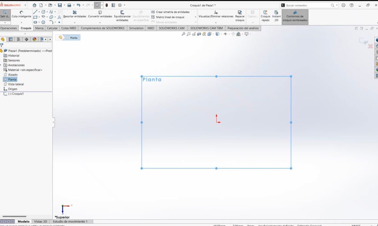
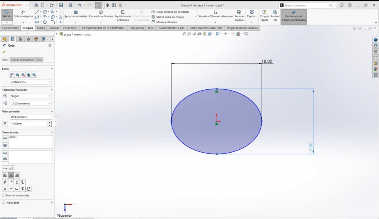
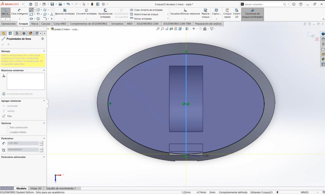
1. Creating a 2D Sketch
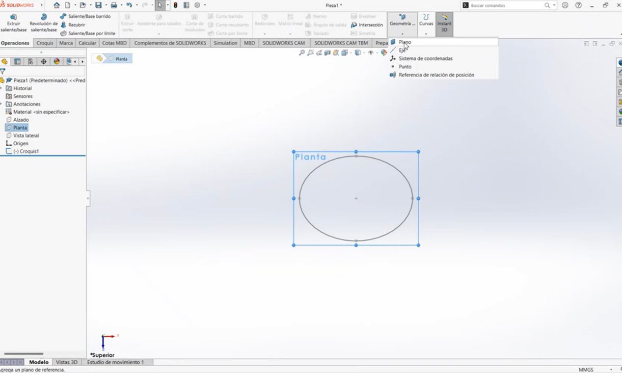
We start by drawing the basic outline of the finger on a plane.
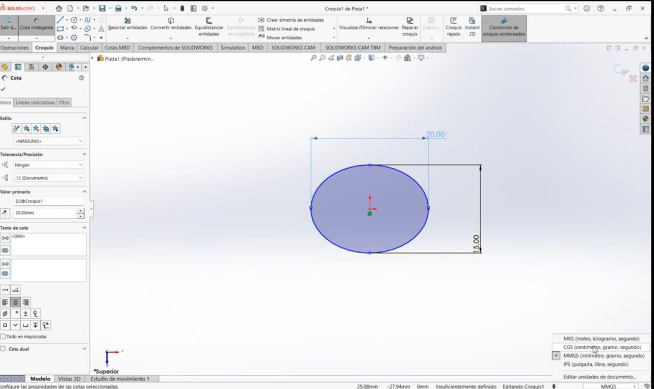
- Command Used: Sketch → Ellipse Tool
- Dimensioning: Smart Dimension to define sizes
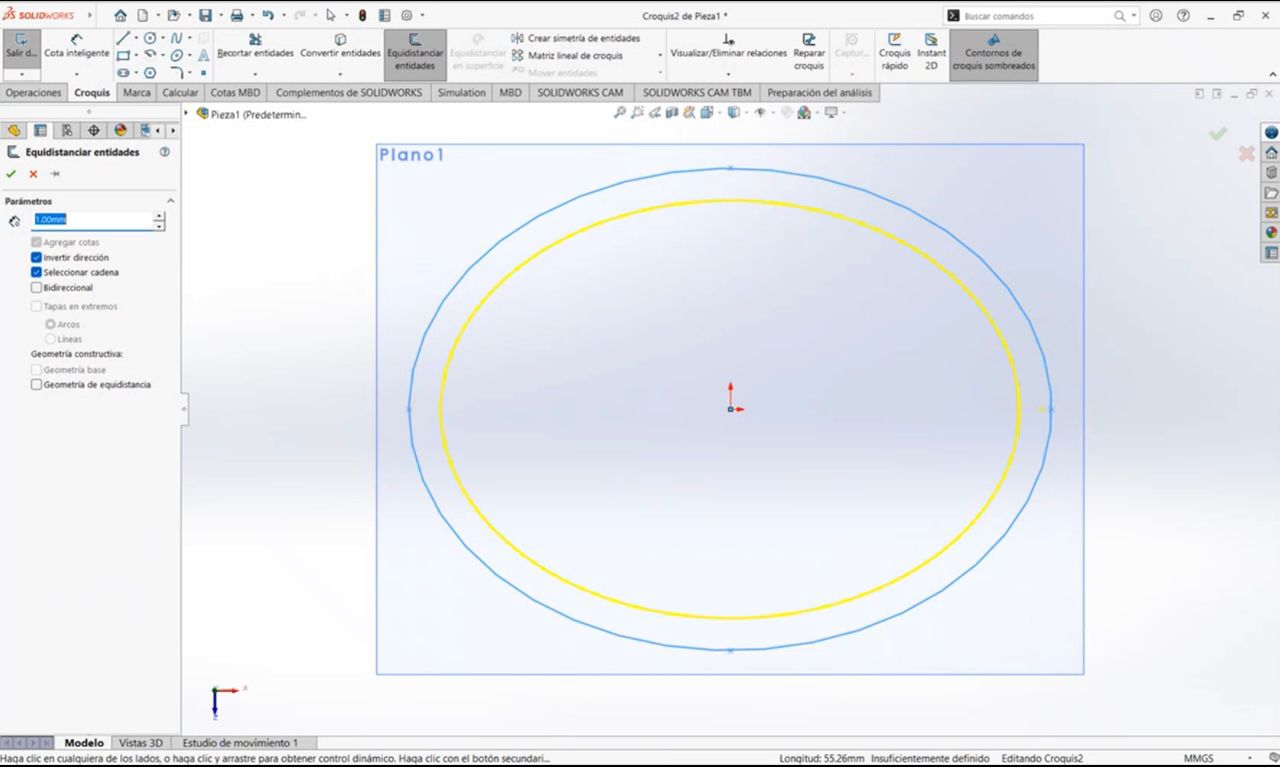
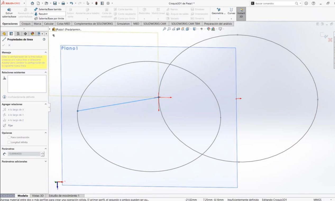
- Create a new plane: A new plane was created and an ellipse was drawn with the same measurements using the Equidistant Entities tool Then, a line was drawn from one point to another, and with the Revolve Tool, the finger shape was created.
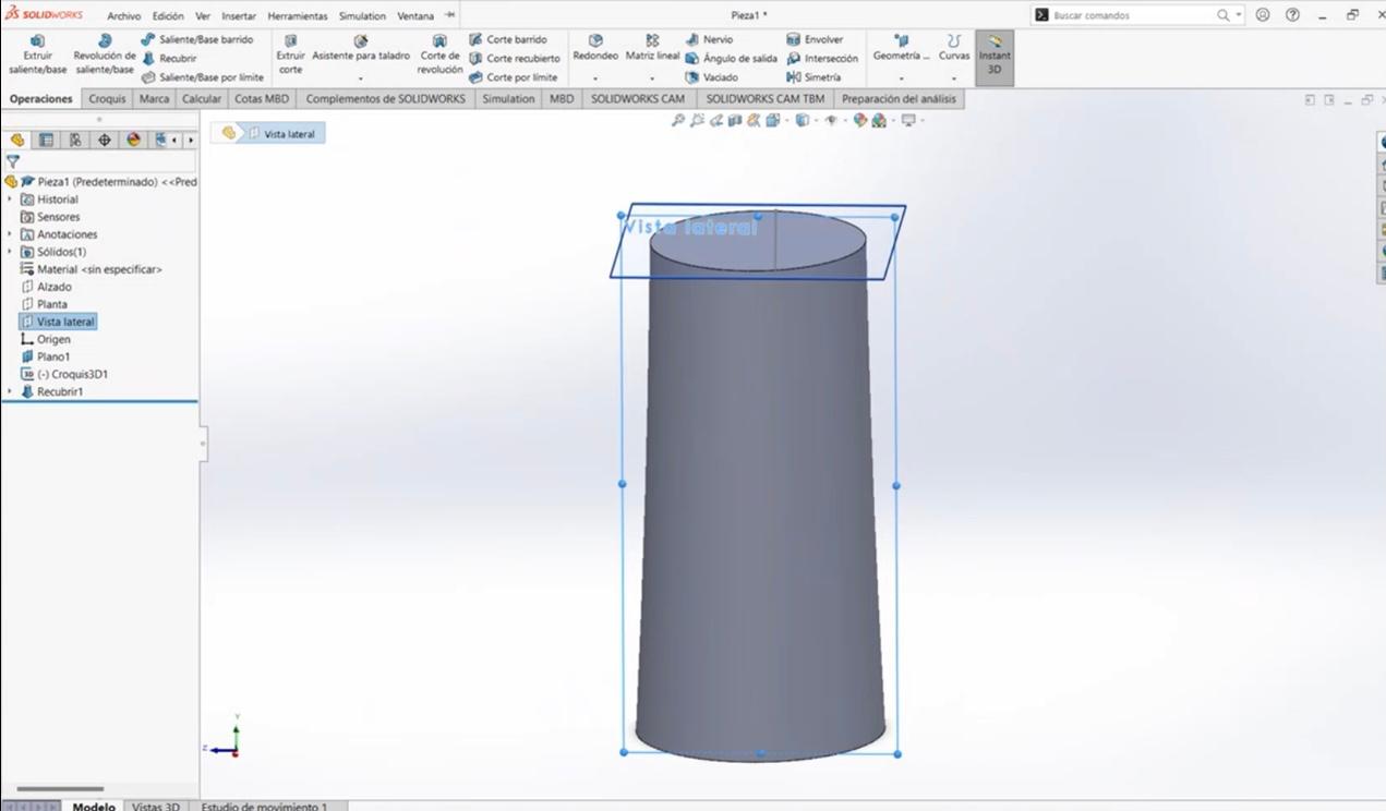
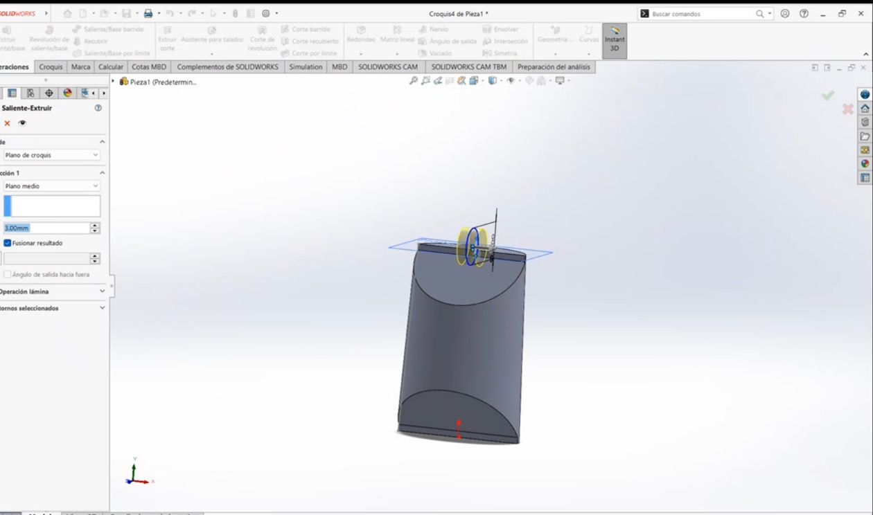
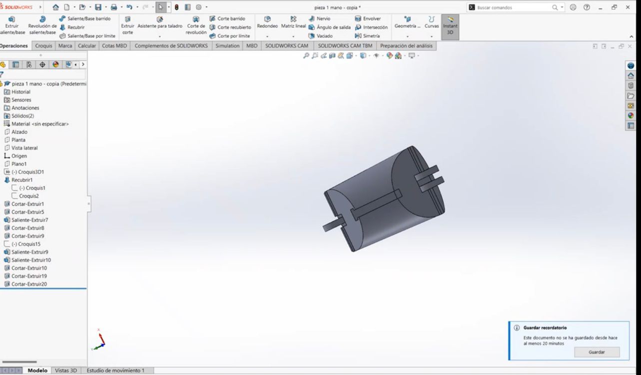
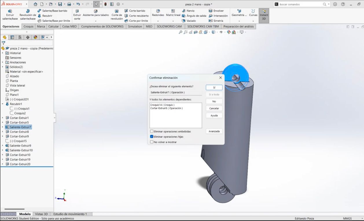
2. Extruding the Sketch and Creating the joints
To convert the 2D sketch into a 3D model, we use extrusion.
- Command Used: Features → Extruded Boss/Base
- Adjust thickness according to your design requirements
After completing the 2D sketch, we proceed with creating additional features.
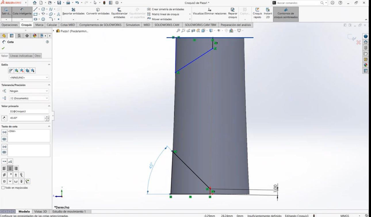
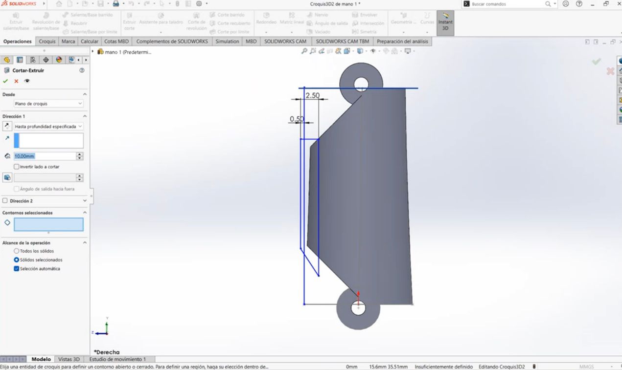
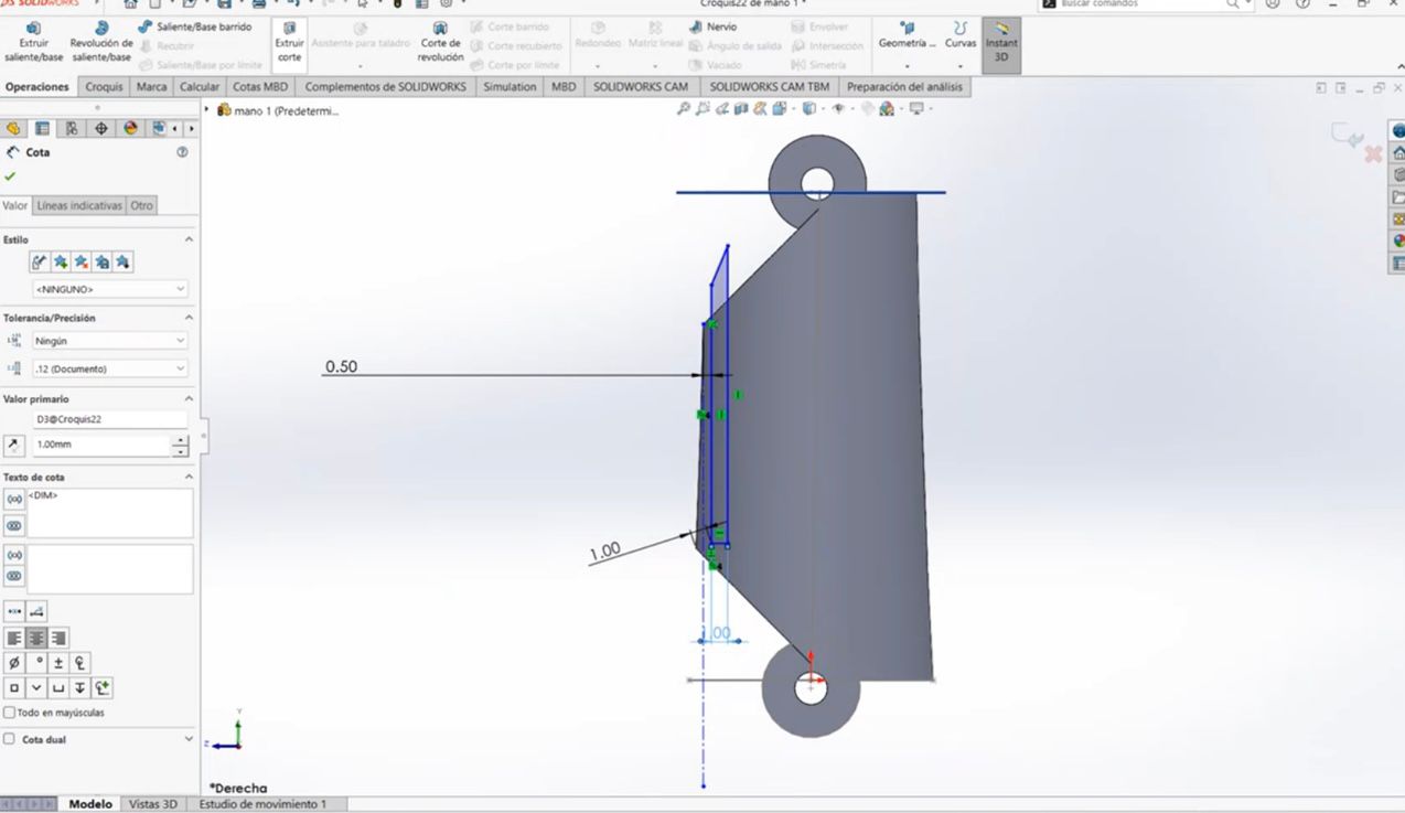
- Creating a Lateral Plane: We create another plane in a lateral view. Using the Line Tool, we form a right triangle shape. With the Smart Dimension tool, we set the desired measurements: a 45° angle and a height of 1 mm.
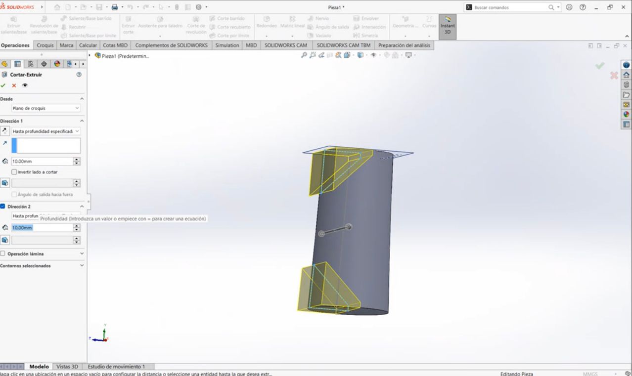
- Extrude Cut: Afterward, we apply an Extrude Cut from the mid-plane, cutting in both directions to obtain the desired shape.
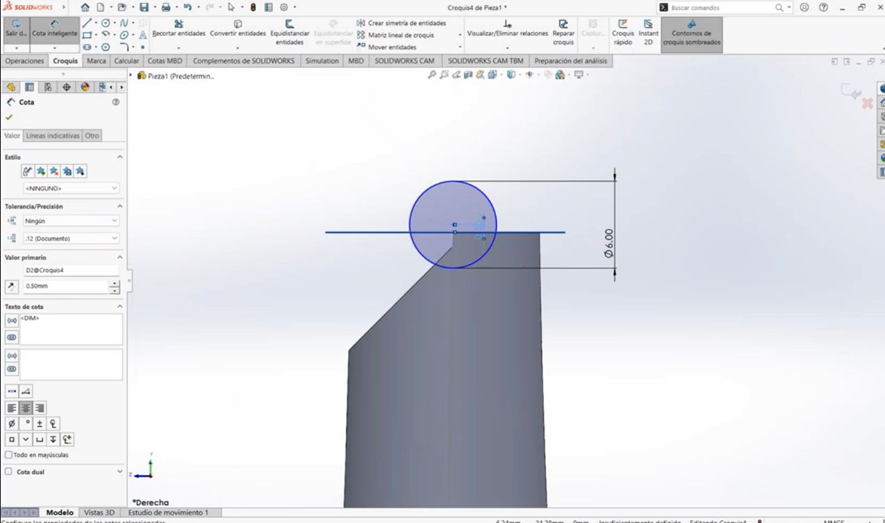
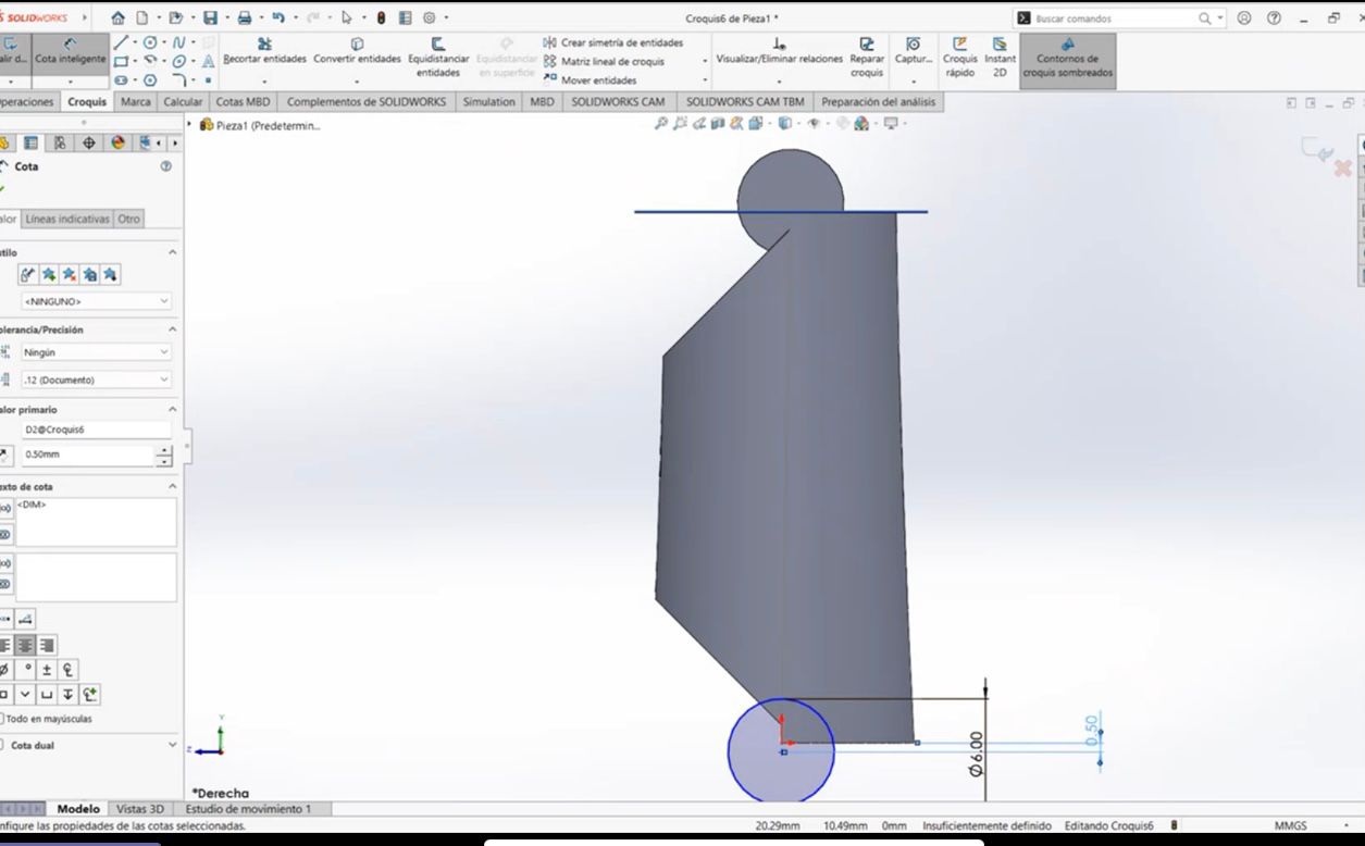
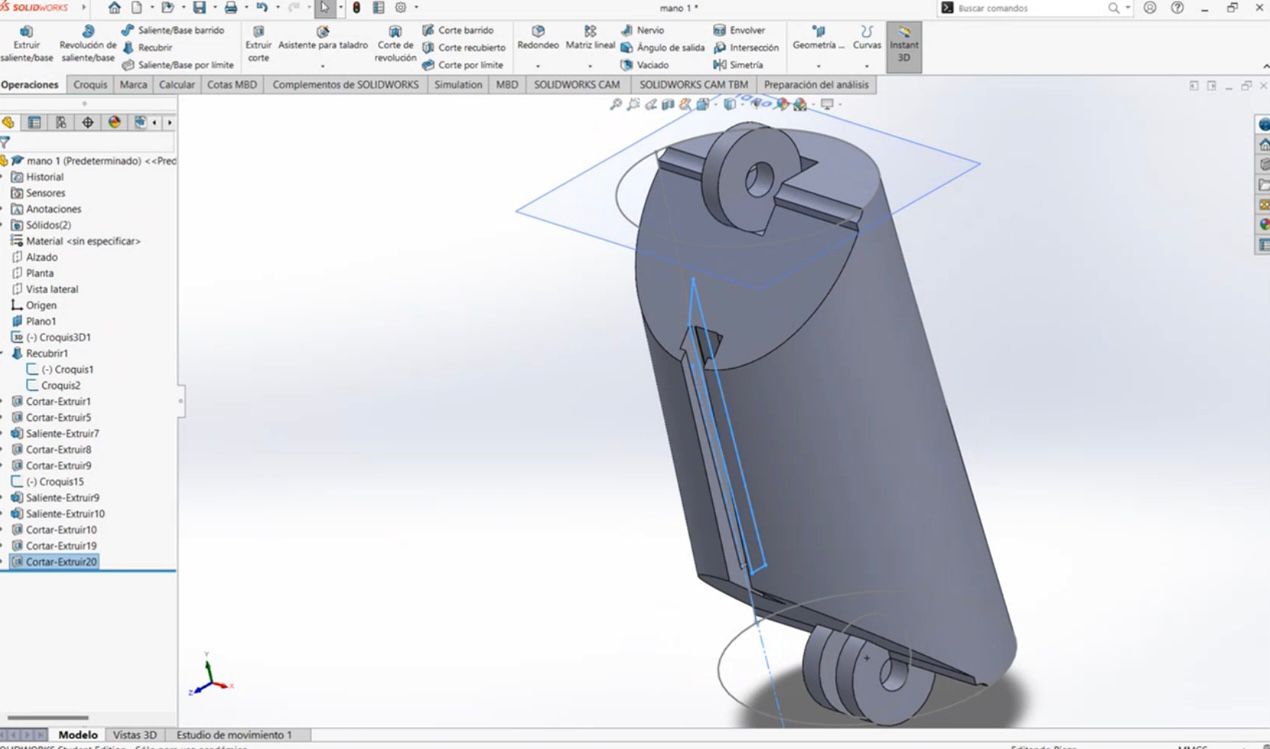
- Creating Falange Unions: We create another lateral plane to make the falange unions. A 6 mm circle is drawn, with a 0.5 mm gap between the center and the created figure. We apply an Extrude Cut on this side, and repeat the same process on the other side.
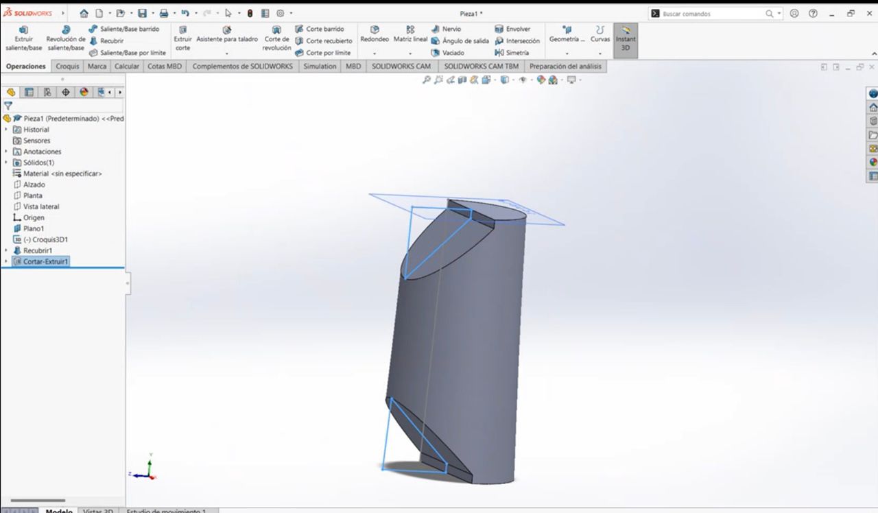
- After completing the extrude cut process, we obtain the following figure.
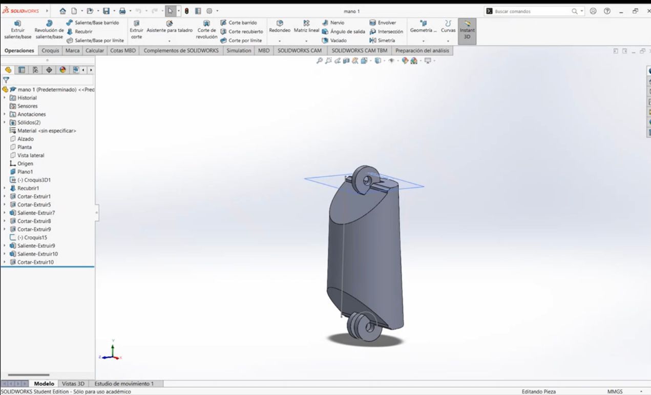
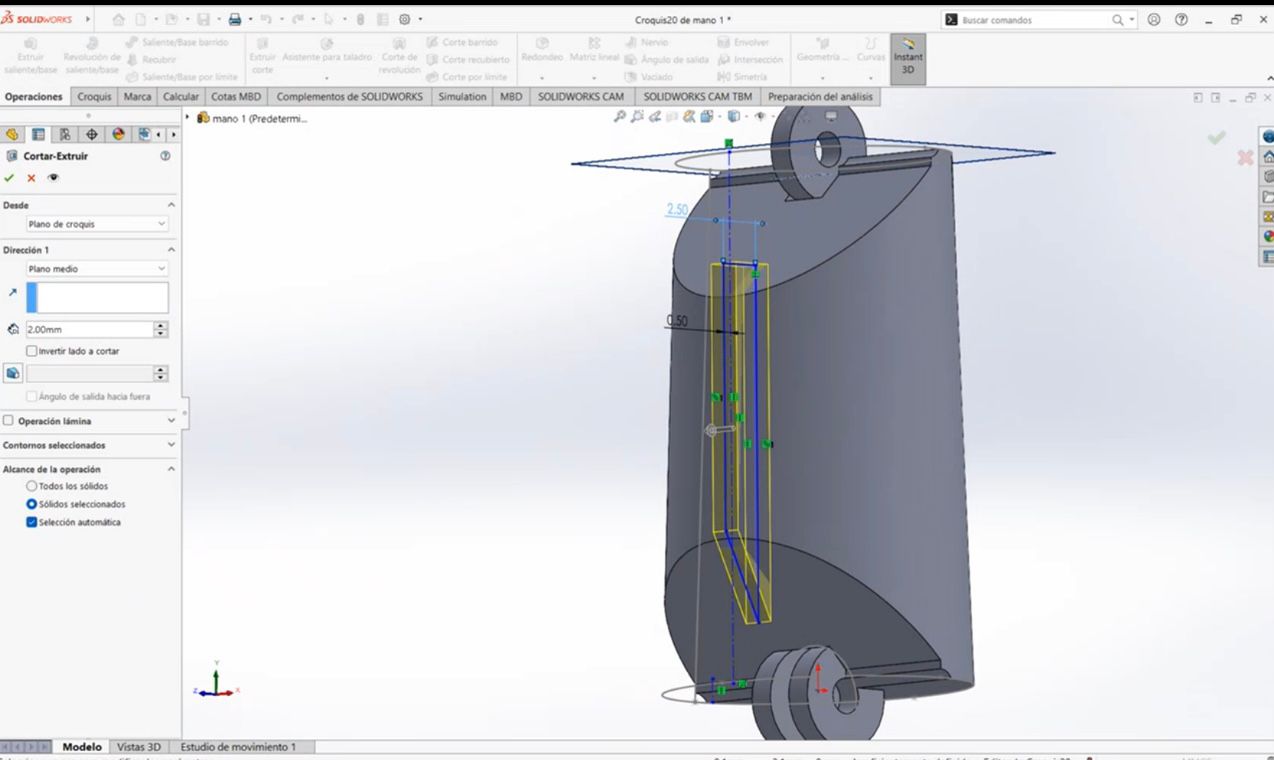
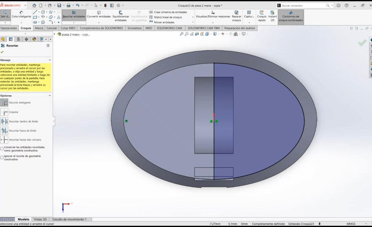
3. Circuitry Area for Flexion Movement
In this section, we will create the area for the circuitry that will control the flexion movement.
We will make two cuts, but first, we create another plane in the lateral view. Using the Line Tool, we draw the figure. It doesn't matter if the lines are long, as long as they cover the base of the finger, that's fine. Then, we extrude that cut starting from the mid-plane.
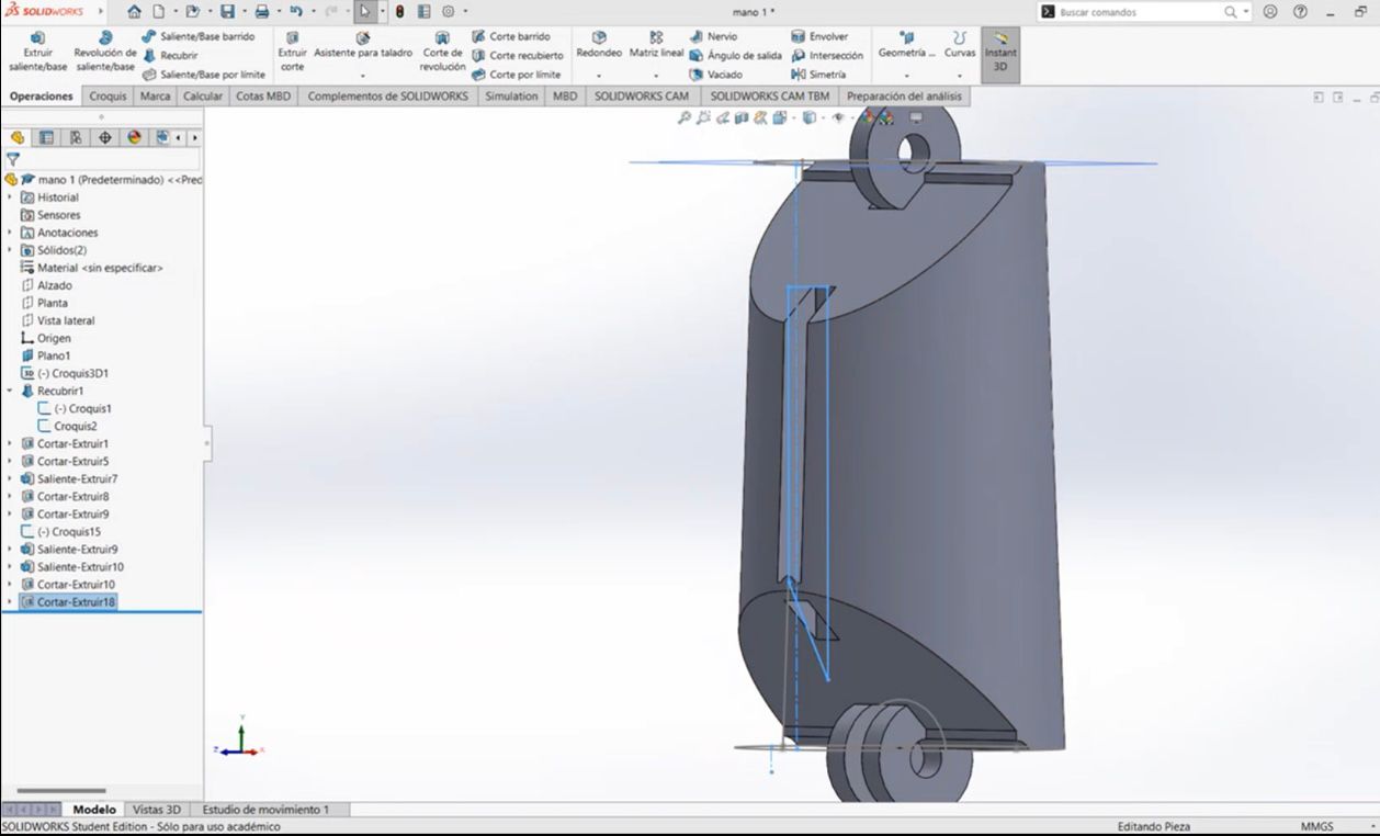
We repeat the process, adjusting the necessary dimensions, and this is the result we get:
4. Creating the Phalanges (Medial and Distal)
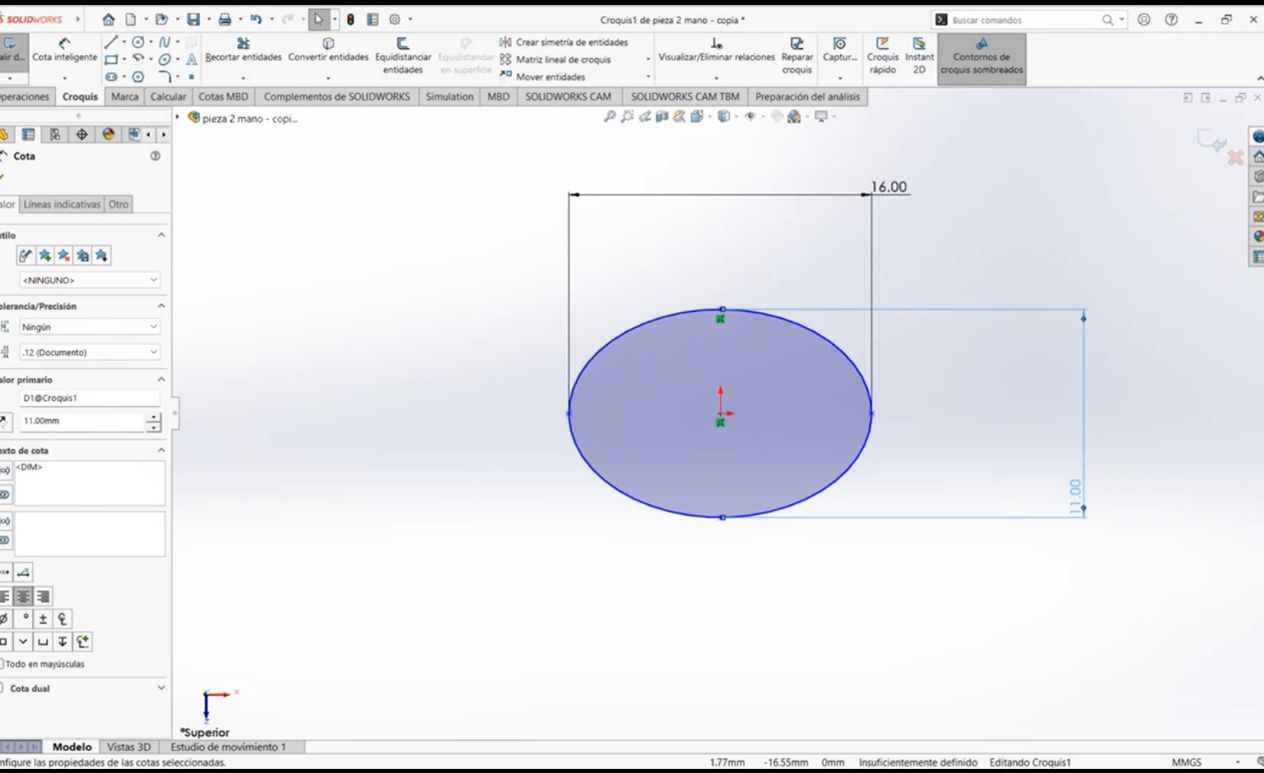
To create the medial and distal phalanges, we open a new part for each one and only need to change the diameter of the initial ellipse.
Medial Phalanx:
For the medial phalanx, we start by creating a new piece and adjust the ellipse diameter accordingly:
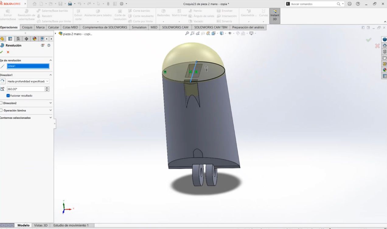
Distal Phalanx:
The process for the distal phalanx is similar: we change the diameter of the ellipse and, on the upper face, remove the union operation. This results in the following shape:
Next, we create another ellipse with the same size as the one we changed. We divide this ellipse in half using the Line Tool and then use the Cut Tool to cut half of the ellipse, resulting in the following:
Finally, using the Revolve Tool, we create the tip of the finger.
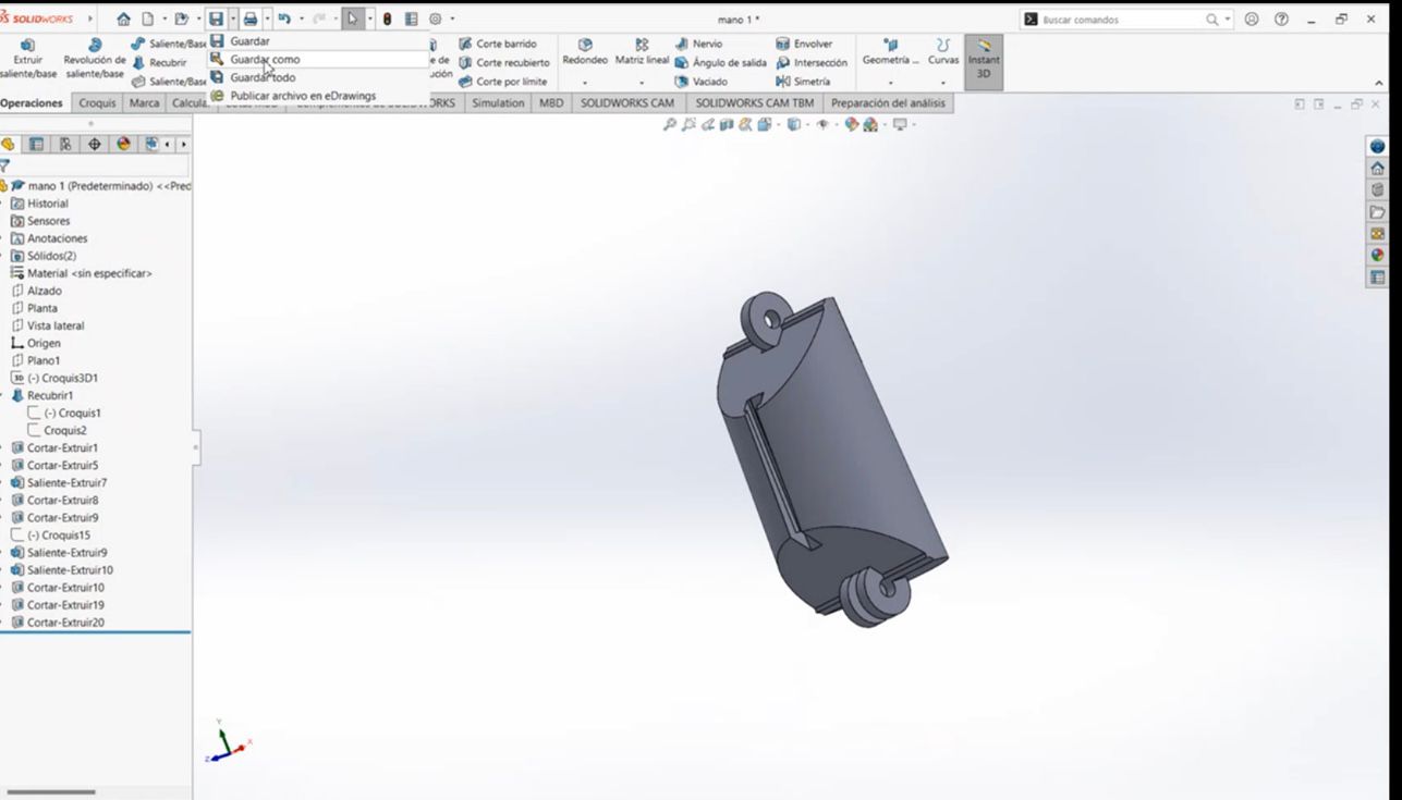
After creating the medial and distal phalanges, we save our three parts and proceed to the assembly stage.
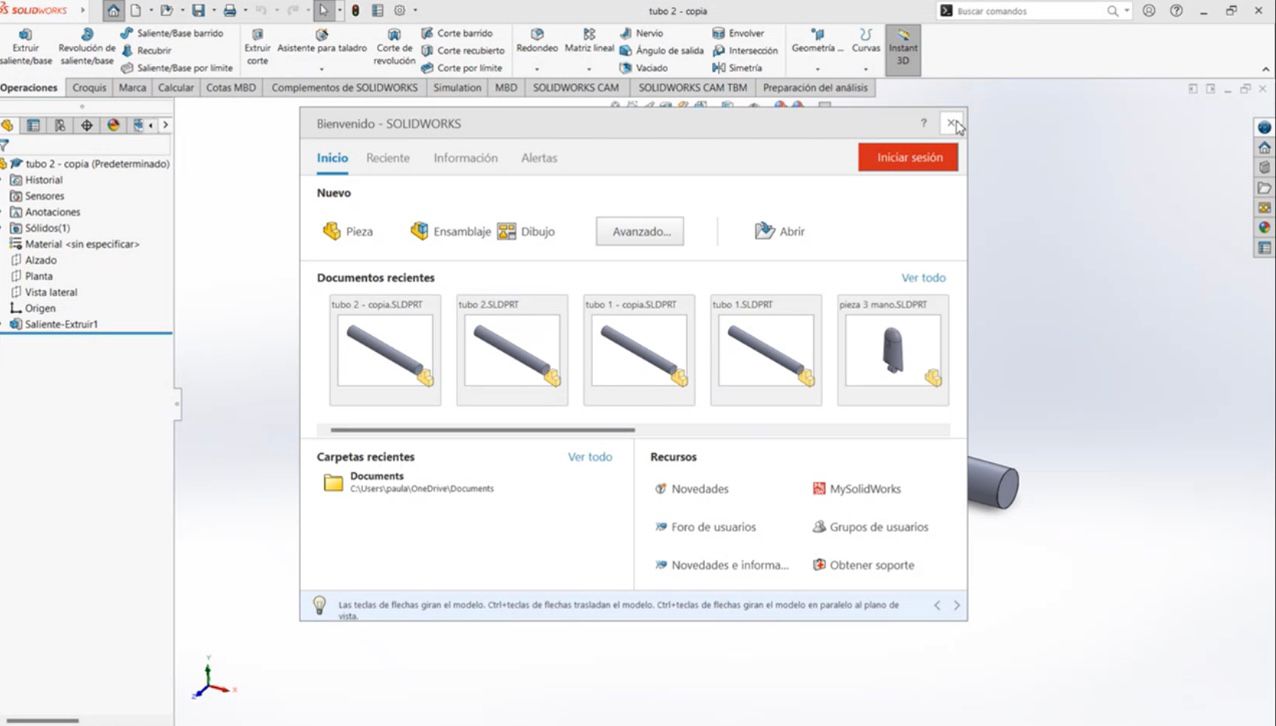
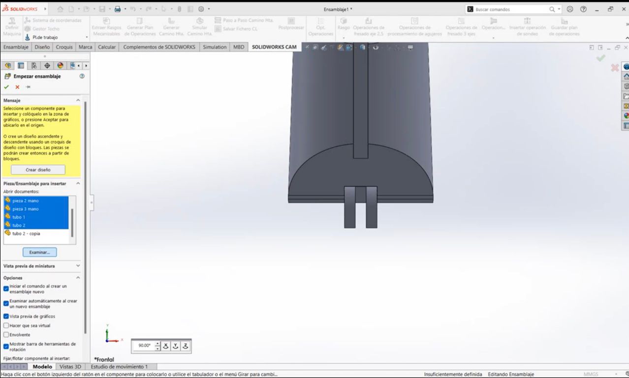
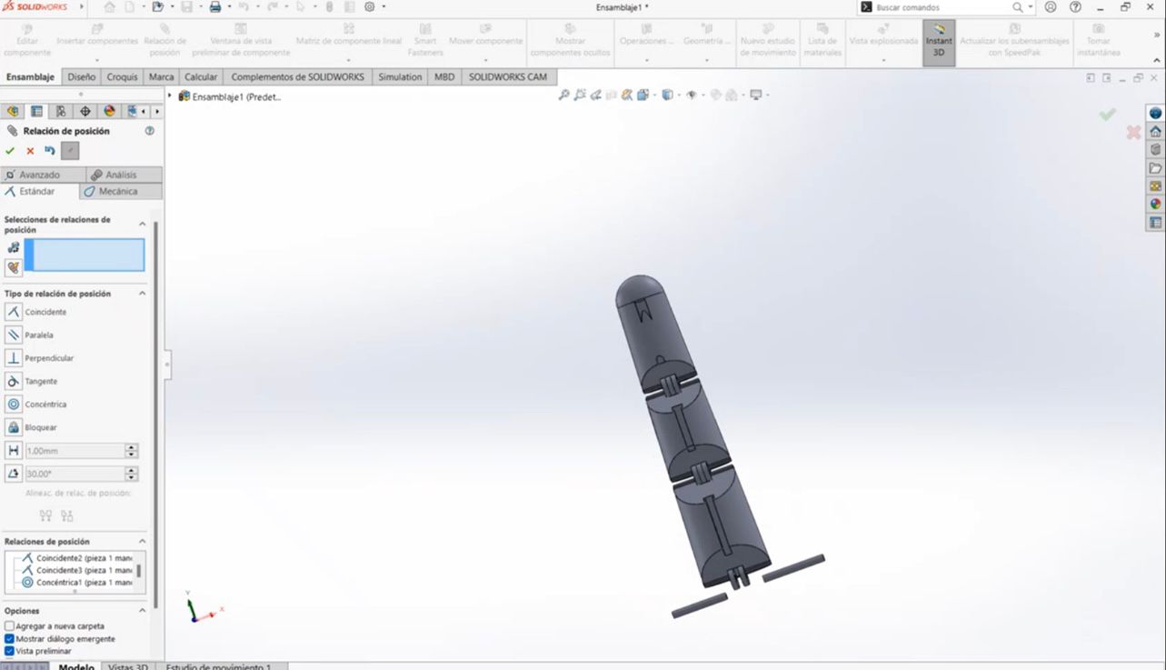
5. Assembling the Finger
To assemble the parts, we open a new document and select Assembly. Once selected, we choose the parts we are going to assemble, in this case, the 3 finger pieces.
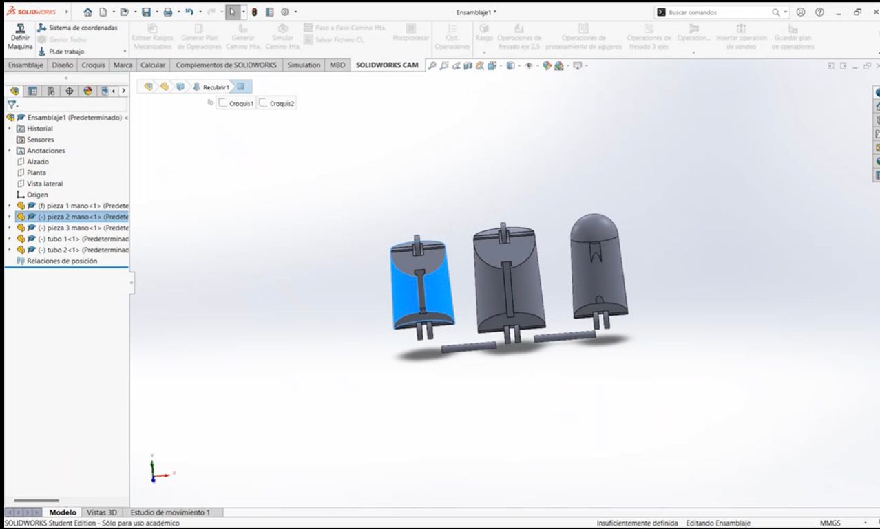
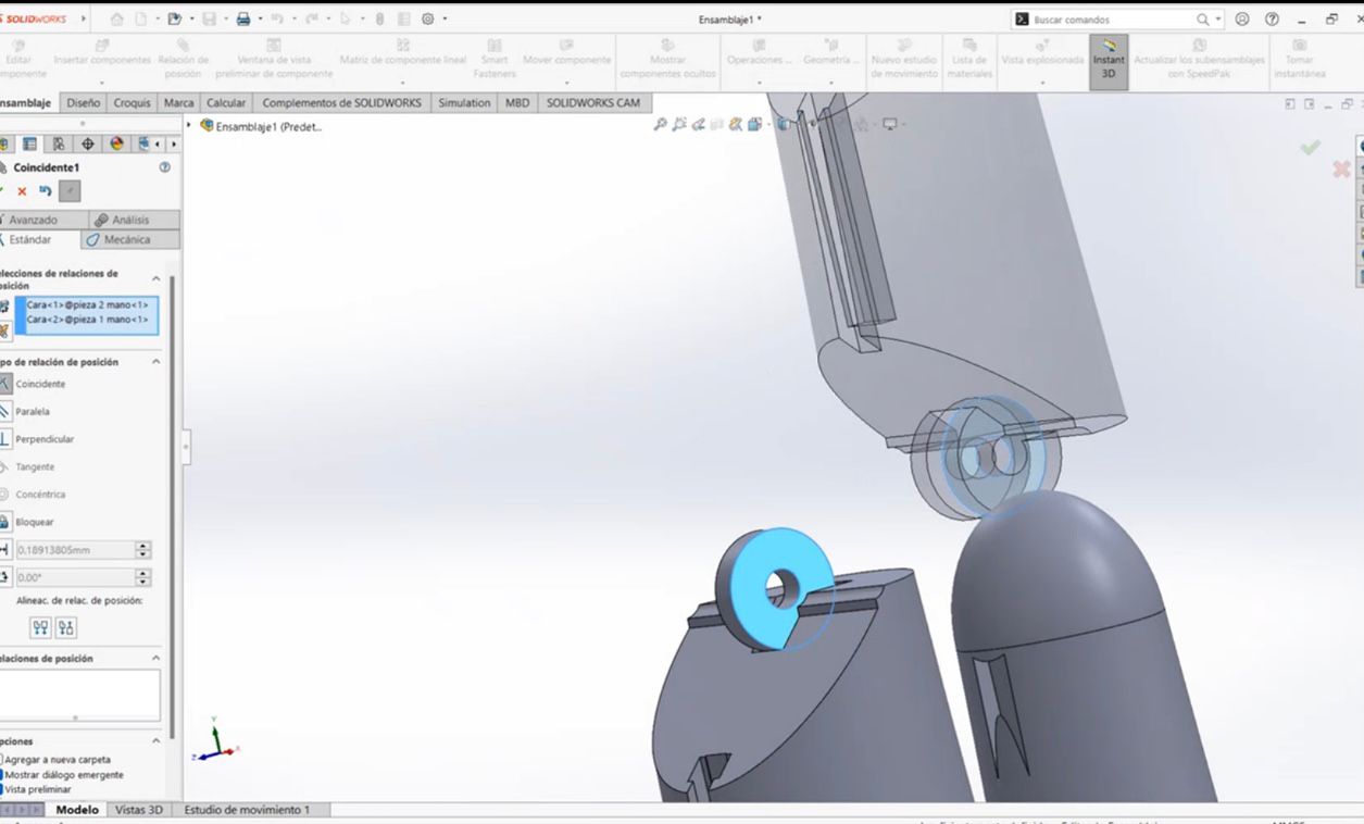
Once we have our pieces, we use the following commands:
- Command Used: Assembly → Mate (for joint constraints)
- Motion Testing: Move Component to check movement
Final Rendered Piece
Finally, this is how the piece looks when rendered:
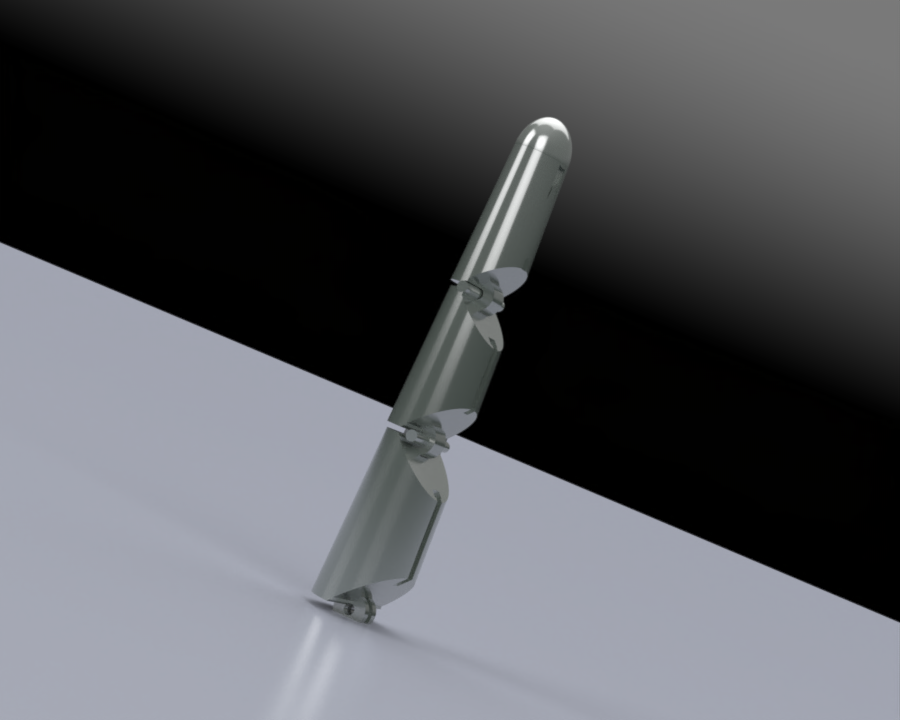
And here we have a better view of the piece:
- Finger assembled
Documents
Comments
By following these steps, we can successfully design a functional robotic finger in SolidWorks. The software provides powerful tools for sketching, modeling, and assembling, making it ideal for mechanical design.
How to Design in Fusion 360
To use Fusion 360 effectively, it is essential to understand some basic commands, just as in SolidWorks, most of the Fusion 360 commands are named the same . Below, I will introduce a few key commands, but if you want to learn more, you can explore an extensive guide with additional tools and commands here: Fusion 360 Command Guide
Basic Commands in Fusion 360
1. Sketching Tools
Fusion 360 allows you to create 2D sketches, which serve as the foundation for 3D models. Some essential sketching tools include:
- Line: Draws straight lines.
- Rectangle: Creates rectangular shapes.
- Circle: Generates circular sketches.
- Dimension: Adds precise measurements to your sketch.
2. Extrude and Revolve
Once you have a sketch, you can convert it into a 3D object using:
- Extrude: Extends a 2D shape into a 3D solid.
- Revolve: Rotates a sketch around an axis to create a 3D shape.
3. Modifying 3D Models
After creating a 3D model, you may need to modify it using:
- Fillet: Rounds the edges of a model.
- Chamfer: Creates beveled edges instead of rounded ones.
- Shell: Removes material from the inside to create a hollow part.
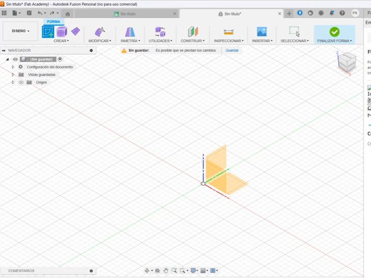
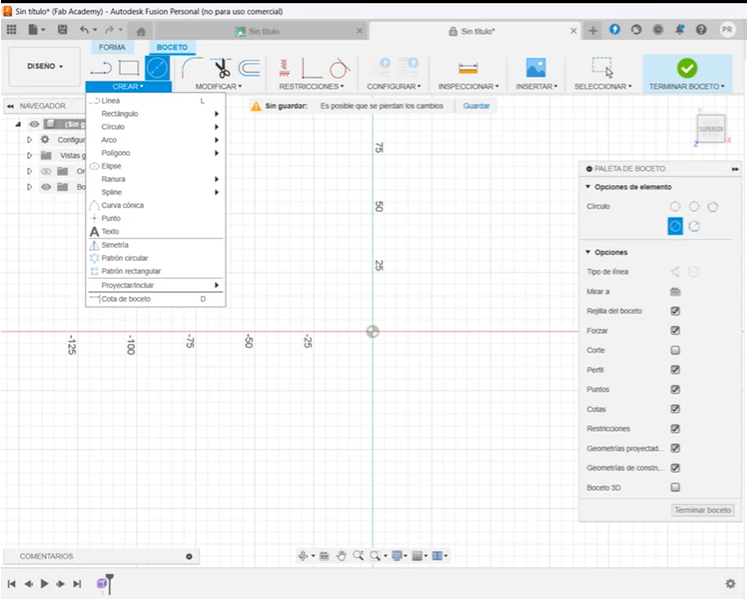
Creating a Sketch in Fusion 360
Just like in SolidWorks, we start by creating a new sketch. Click on "Create Sketch" and select a plane where you want to work.
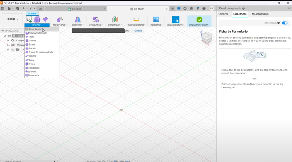
Using Drawing Tools
Next, in the command bar, we find the "Create" menu. Hover over it to reveal all the available tools for drawing, from basic lines to complex shapes. In this example, I will create a butterfly cutter.
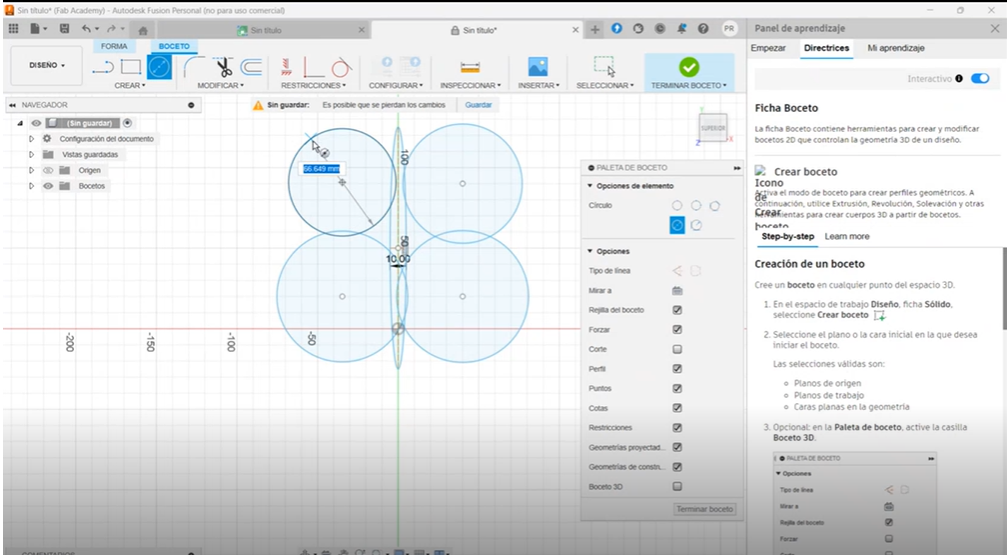
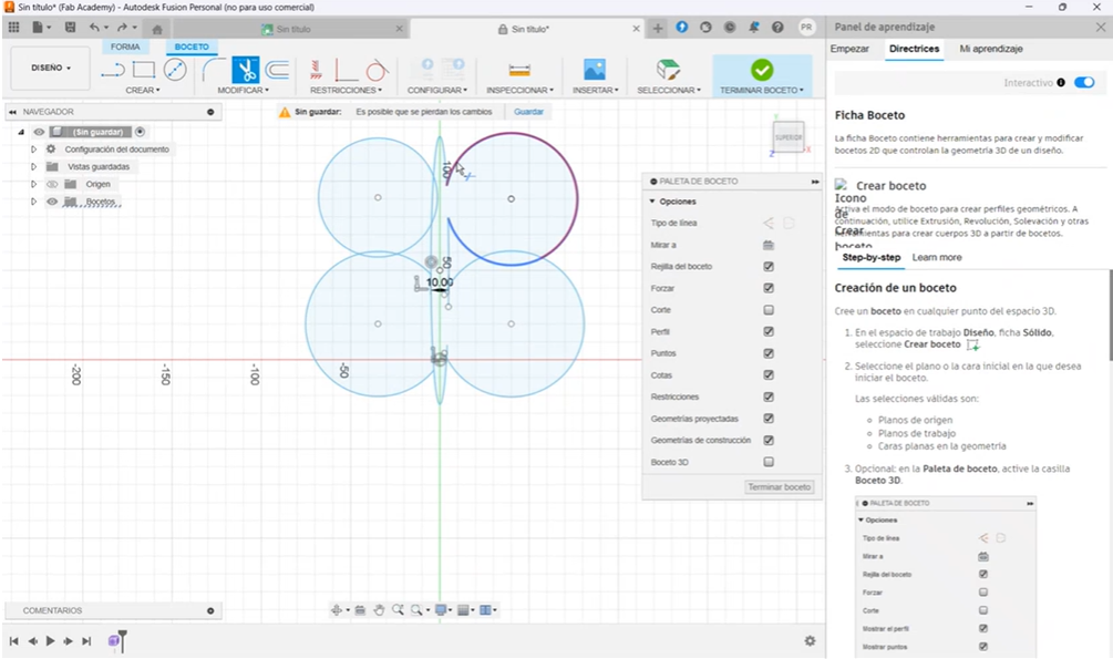
Refining the Sketch
Using the "Trim" tool, we remove excess edges to ensure the shape remains a single, unified piece.
Extruding the Sketch
After finalizing the sketch, we go back to the "Create" tab and select "Extrude" to give our piece a 3D shape.
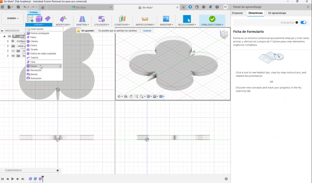
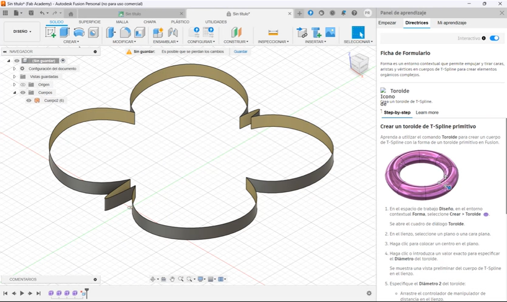
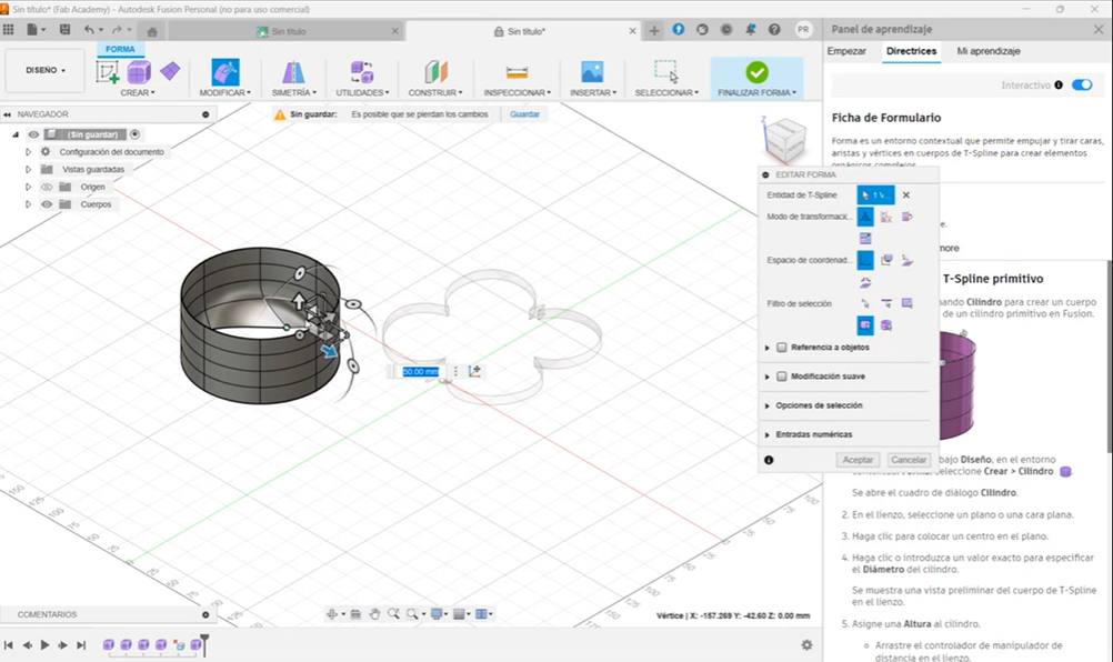
3D Modeling in Fusion 360
Fusion 360 also offers the option to create 3D models using predefined shapes, similar to sculpting clay. By using the "Modify" tool, we can manipulate these shapes to achieve unique forms that are difficult to create with standard geometric tools.
- Butterfly Shaped cutter
Documents
Pro Tip: Reduce the Size of Your Evidence and Documents!
For this activity, since the design process was extensive, I decided to record my screen using Microsoft Teams throughout the entire process.
Since the video was stored on a platform that also has a mobile app, I watched the recording on my phone, took screenshots of the most important parts, and sent them to myself via WhatsApp Web. Finally, I downloaded them to my computer. This way, all the images only took up a few KB.
For my SolidWorks files, since it was an assembly, I compressed everything into a ZIP folder, reducing the file size significantly to just a few KB. I used this method for every task this week.
Conclusion of This Week's Assignment: Computer-Aided Design
Throughout this week's assignment on Computer-Aided Design, I learned how to use different design tools to create more functional, modern, and ergonomic prototypes.
Regarding Adobe Illustrator and Inkscape, I personally preferred Adobe’s interface and tools, as they feel more intuitive and user-friendly for any user. Inkscape, on the other hand, is a very complete platform, but I feel its interface could be improved. However, it remains an accessible option for anyone.
When comparing SolidWorks and Fusion 360, both platforms offer similar tools. I had previously used SolidWorks for some tasks, and while it has many advanced features, I believe I can still improve my skills with it. If you're new to CAD design, I recommend taking a course to learn the proper commands and maximize its potential.
Fusion 360 is a user-friendly platform, although its interface could be improved to be even more intuitive. One of its standout features is the ability to create objects from predefined 3D shapes and modify them freely, allowing for greater creativity in design. I had never used Fusion 360 before, but I really enjoyed the platform and would definitely recommend it to beginners
If you are a professional engineer or work in an industrial setting, SolidWorks is a great investment. However, if you are a student, or need a more flexible and accessible tool, Fusion 360 is an excellent free alternative.
- © Copyright 2025 [Paula Rivero Robledo]
- Creative Commons Attribution Non Commercial