1. Input Devices
1. Input Devices
This week, we delved into the world of input devices. The XIAO ESP32S3, equipped with a Sense expansion board, features a camera interface and a microphone interface. Given that my final project is an intelligent glasses kit, I require a camera, a microphone, and a six-axis sensor.
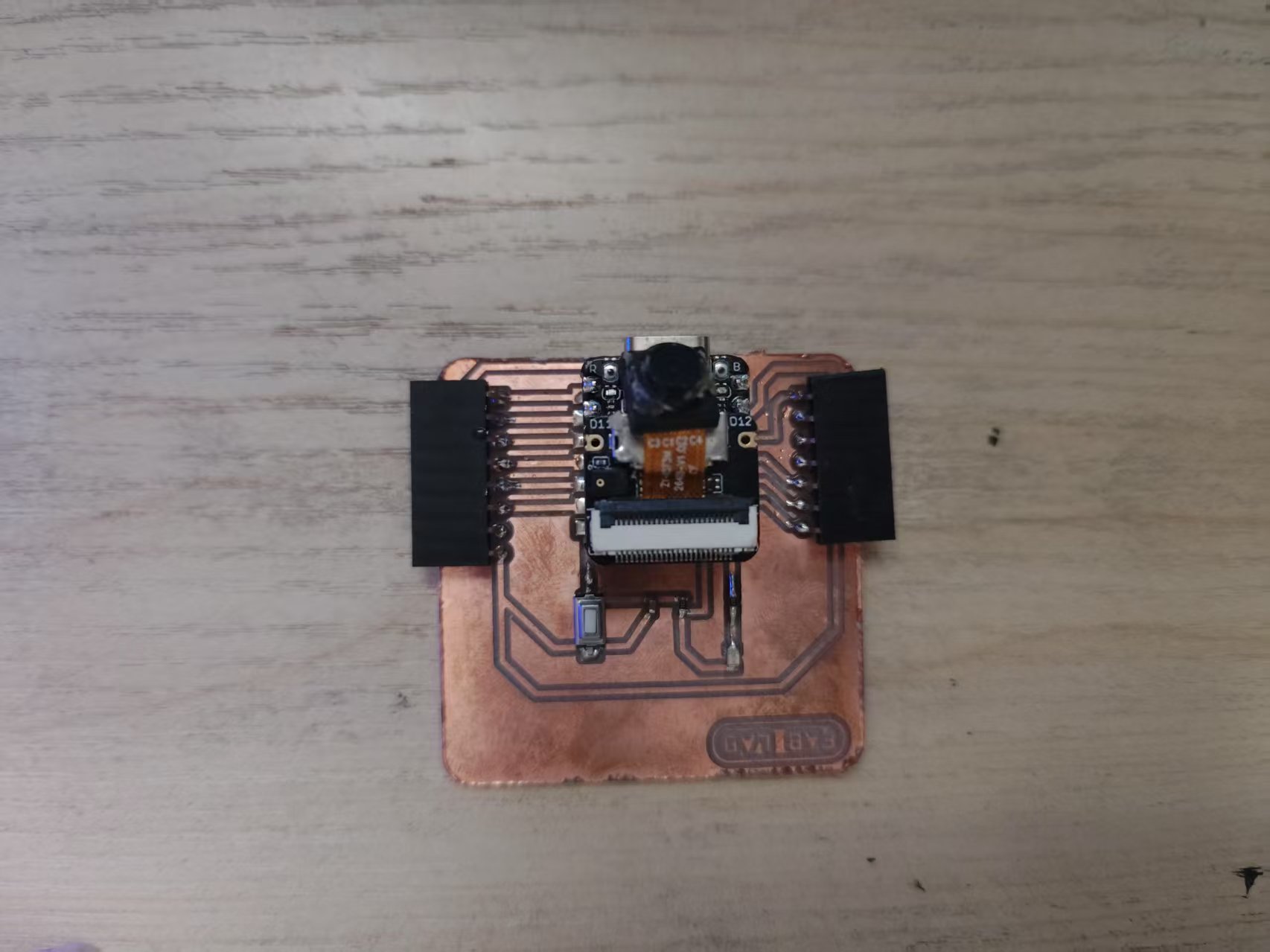
1.1 Camera
The XIAO ESP32S3 utilizes a Parallel Camera interface, which requires the following pins:
- VSYNC: Frame synchronization signal, transitioning from low to high voltage at the start of each frame.
- HSYNC: Line synchronization signal, transitioning from low to high voltage at the start of each line.
- MCLK: Camera operating clock signal, providing the clock for the camera.
- PCLK: Pixel clock signal, synchronizing pixel data.
- D0-D7: Pixel data, an 8-bit parallel data bus.
I am using the OV2640 camera, which supports a resolution of up to 1600x1200.
The program, written in ESP-IDF, captures images and sends them via an HTTP server.
All project code is open-source and available at the following link: Camera Example Code
#include <esp_log.h>
#include <esp_system.h>
#include <nvs_flash.h>
#include <sys/param.h>
#include <string.h>
#include <driver/i2c.h>

#include "freertos/FreeRTOS.h"
#include "freertos/task.h"

#include "esp_netif.h"
#include "nvs_flash.h"
#include "esp_wifi.h"
#include "esp_event.h"

#include "esp_camera.h"
#include "esp_http_server.h"
#include "esp_timer.h"

#include "iperf_cmd.h"

#include "console_wifi.h"

#define PART_BOUNDARY "123456789000000000000987654321"
static const char *_STREAM_CONTENT_TYPE = "multipart/x-mixed-replace;boundary=" PART_BOUNDARY;
static const char *_STREAM_BOUNDARY = "\r\n--" PART_BOUNDARY "\r\n";
static const char *_STREAM_PART = "Content-Type: image/jpeg\r\nContent-Length: %u\r\n\r\n";

#define TAG "main"

esp_err_t jpg_stream_httpd_handler(httpd_req_t *req)
{
    camera_fb_t *fb = NULL;
    esp_err_t res = ESP_OK;
    size_t _jpg_buf_len;
    uint8_t *_jpg_buf;
    char *part_buf[64];
    static int64_t last_frame = 0;
    if (!last_frame)
    {
        last_frame = esp_timer_get_time();
    }

    res = httpd_resp_set_type(req, _STREAM_CONTENT_TYPE);
    if (res != ESP_OK)
    {
        return res;
    }

    while (true)
    {
        fb = esp_camera_fb_get();
        if (!fb)
        {
            ESP_LOGE(TAG, "Camera capture failed");
            res = ESP_FAIL;
            break;
        }
        if (fb->format != PIXFORMAT_JPEG)
        {
            ESP_LOGI(TAG, "Converting JPEG...");
            bool jpeg_converted = frame2jpg(fb, 80, &_jpg_buf, &_jpg_buf_len);
            if (!jpeg_converted)
            {
                ESP_LOGE(TAG, "JPEG compression failed");
                esp_camera_fb_return(fb);
                res = ESP_FAIL;
            }
        }
        else
        {
            _jpg_buf_len = fb->len;
            _jpg_buf = fb->buf;
        }

        if (res == ESP_OK)
        {
            res = httpd_resp_send_chunk(req, _STREAM_BOUNDARY, strlen(_STREAM_BOUNDARY));
        }
        if (res == ESP_OK)
        {
            size_t hlen = snprintf((char *)part_buf, 64, _STREAM_PART, _jpg_buf_len);

            res = httpd_resp_send_chunk(req, (const char *)part_buf, hlen);
        }
        if (res == ESP_OK)
        {
            res = httpd_resp_send_chunk(req, (const char *)_jpg_buf, _jpg_buf_len);
        }
        if (fb->format != PIXFORMAT_JPEG)
        {
            free(_jpg_buf);
        }
        esp_camera_fb_return(fb);
        if (res != ESP_OK)
        {
            break;
        }
        int64_t fr_end = esp_timer_get_time();
        int64_t frame_time = fr_end - last_frame;
        last_frame = fr_end;
        frame_time /= 1000;
        ESP_LOGI(TAG, "MJPG: %luKB %lums (%.1ffps)", (uint32_t)(_jpg_buf_len / 1024), (uint32_t)frame_time, 1000.0 / (uint32_t)frame_time);
    }

    last_frame = 0;
    return res;
}

#define CAM_PIN_PWDN  -1
#define CAM_PIN_RESET -1

#define CAM_PIN_VSYNC 38
#define CAM_PIN_HREF  47
#define CAM_PIN_PCLK  13
#define CAM_PIN_XCLK  10

#define CAM_PIN_SIOD 40
#define CAM_PIN_SIOC 39

#define CAM_PIN_D0 15
#define CAM_PIN_D1 17
#define CAM_PIN_D2 18
#define CAM_PIN_D3 16
#define CAM_PIN_D4 14
#define CAM_PIN_D5 12
#define CAM_PIN_D6 11
#define CAM_PIN_D7 48

static camera_config_t camera_config = {
    .pin_pwdn = CAM_PIN_PWDN,
    .pin_reset = CAM_PIN_RESET,
    .pin_xclk = CAM_PIN_XCLK,
    .pin_sccb_sda = CAM_PIN_SIOD,
    .pin_sccb_scl = CAM_PIN_SIOC,

    .pin_d7 = CAM_PIN_D7,
    .pin_d6 = CAM_PIN_D6,
    .pin_d5 = CAM_PIN_D5,
    .pin_d4 = CAM_PIN_D4,
    .pin_d3 = CAM_PIN_D3,
    .pin_d2 = CAM_PIN_D2,
    .pin_d1 = CAM_PIN_D1,
    .pin_d0 = CAM_PIN_D0,
    .pin_vsync = CAM_PIN_VSYNC,
    .pin_href = CAM_PIN_HREF,
    .pin_pclk = CAM_PIN_PCLK,

    .xclk_freq_hz = 20000000,
    .ledc_timer = LEDC_TIMER_0,
    .ledc_channel = LEDC_CHANNEL_0,

    .frame_size = FRAMESIZE_QVGA,

    .jpeg_quality = 12, // 0-63, for OV series camera sensors, lower number means higher quality
    .fb_count = 2,      // When jpeg mode is used, if fb_count more than one, the driver will work in continuous mode.
    .fb_location = CAMERA_FB_IN_PSRAM,
    .grab_mode = CAMERA_FB_IN_PSRAM,
};

void app_main(void)
{
    ESP_ERROR_CHECK(esp_netif_init());
    ESP_ERROR_CHECK(esp_event_loop_create_default());
    esp_err_t ret = nvs_flash_init(); // Initialize NVS
    if (ret == ESP_ERR_NVS_NO_FREE_PAGES || ret == ESP_ERR_NVS_NEW_VERSION_FOUND)
    {
        ESP_ERROR_CHECK(nvs_flash_erase());
        ret = nvs_flash_init();
    }

    ESP_ERROR_CHECK(esp_camera_init(&camera_config));

    sensor_t *sensor = esp_camera_sensor_get();
    // sensor->set_vflip(sensor, 1);
    sensor->set_hmirror(sensor, 1);

    httpd_handle_t server = NULL;
    httpd_config_t config = HTTPD_DEFAULT_CONFIG();

    /* Use the URI wildcard matching function in order to
     * allow the same handler to respond to multiple different
     * target URIs which match the wildcard scheme */
    config.uri_match_fn = httpd_uri_match_wildcard;

    ESP_LOGI(TAG, "Starting HTTP Server on port: '%d'", config.server_port);
    ESP_ERROR_CHECK(httpd_start(&server, &config));

    /* URI handler for getting uploaded files */
    httpd_uri_t stream = {
        .uri = "/stream", // Match all URIs of type /path/to/file
        .method = HTTP_GET,
        .handler = jpg_stream_httpd_handler,
        .user_ctx = NULL // Pass server data as context
    };

    httpd_register_uri_handler(server, &stream);
    uint32_t frame_time = 0;

    // Initialize console REPL
    ESP_ERROR_CHECK(console_cmd_init());

    ESP_ERROR_CHECK(console_cmd_wifi_register());

    // start console REPL
    ESP_ERROR_CHECK(console_cmd_start());
}
Compile and flash the program to the XIAO ESP32S3:
idf.py build
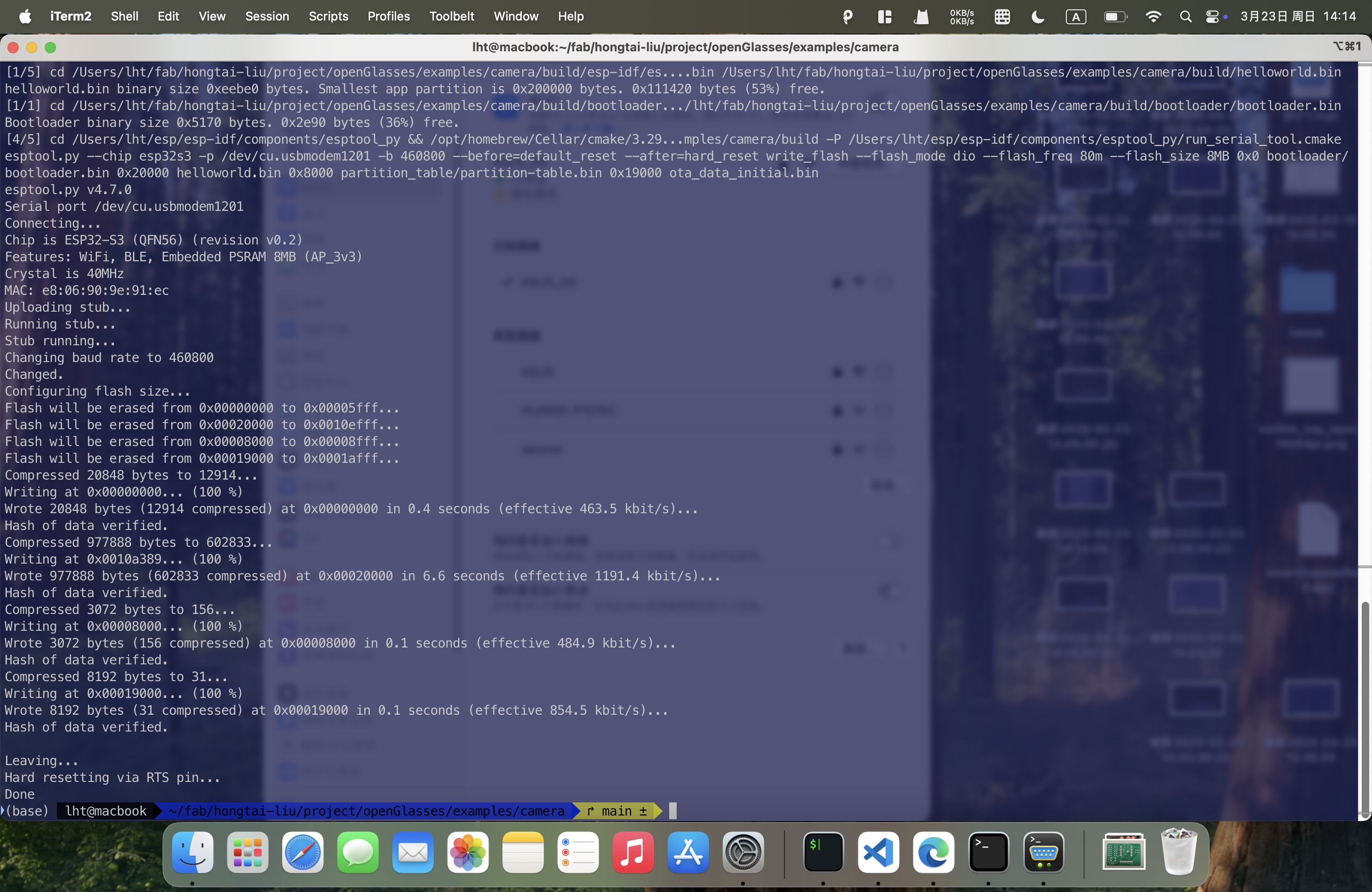
idf.py flash
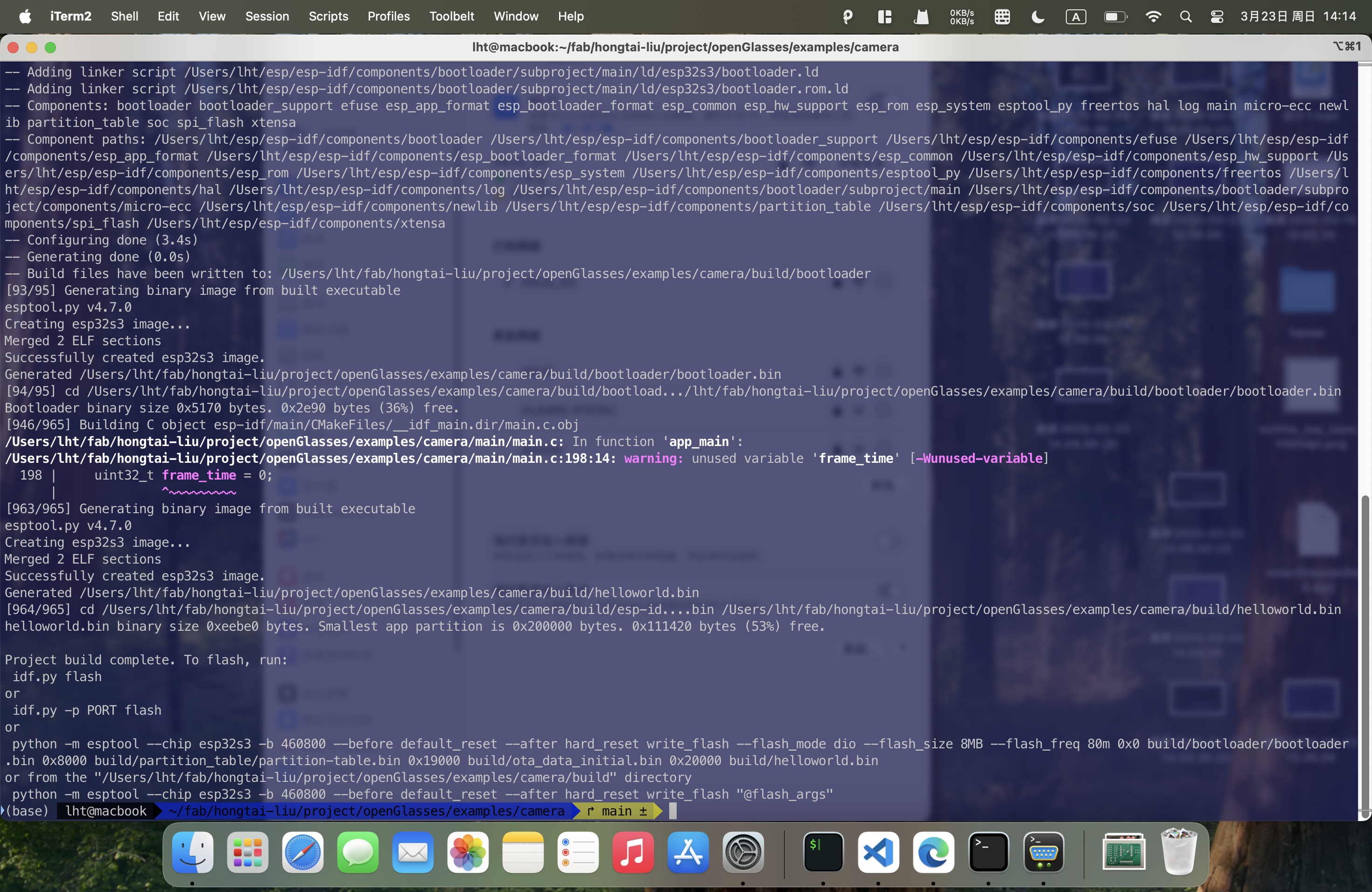
Open the serial monitor:
idf.py monitor
Connect the device to the same network as your PC using the serial command. Then, enter the device's IP address and port number in a browser to view the live camera feed.
> wifi sta join <ssid> <password>
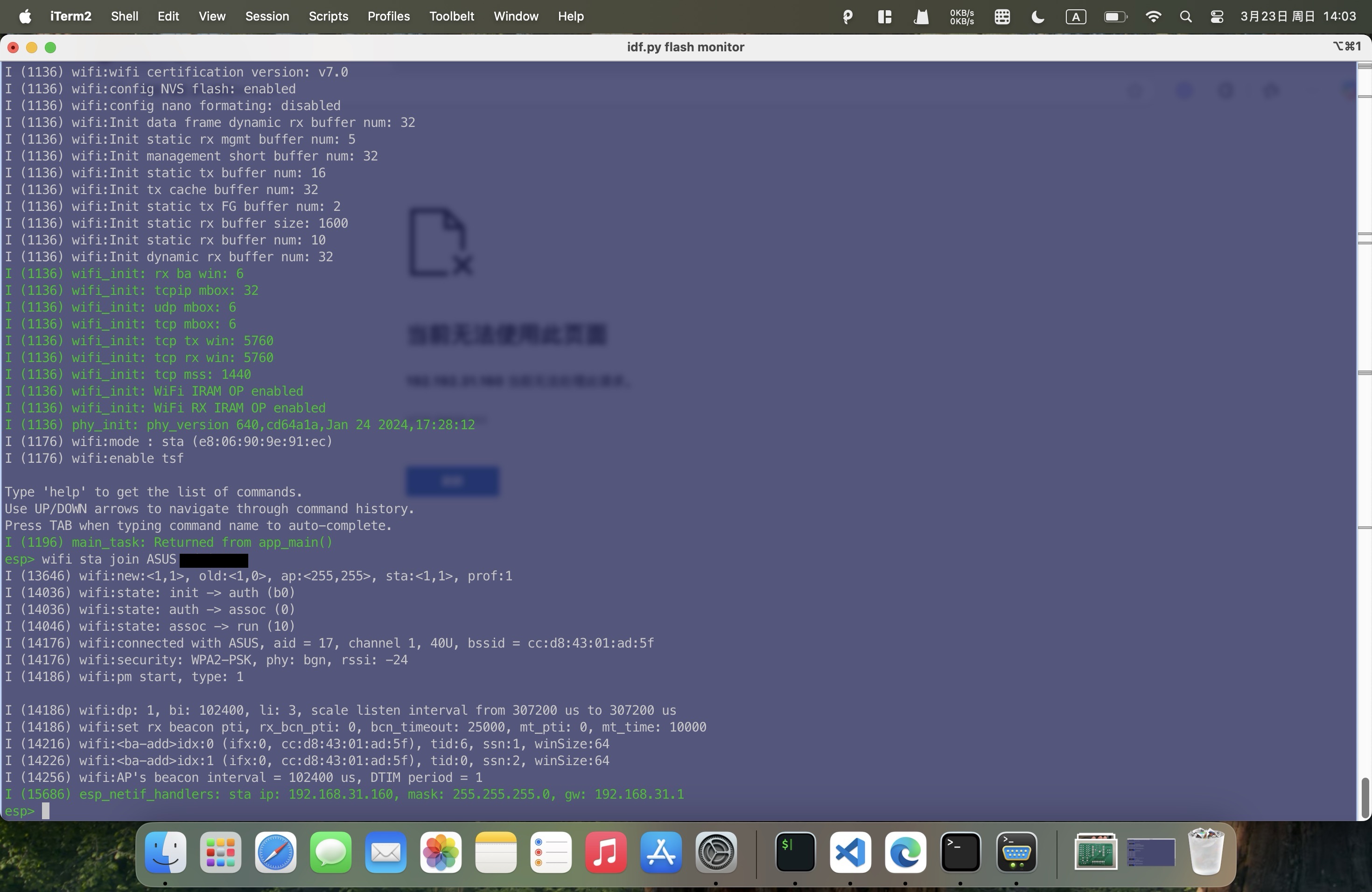
Enter http://<device-ip>:<port>/stream in the browser to view the live camera feed.

1.2 Microphone
The XIAO ESP32S3 utilizes a DMIC interface, which requires the following pins:
- CLK: Clock signal, synchronizing audio data.
- DATA: Audio data, 8-bit serial data.
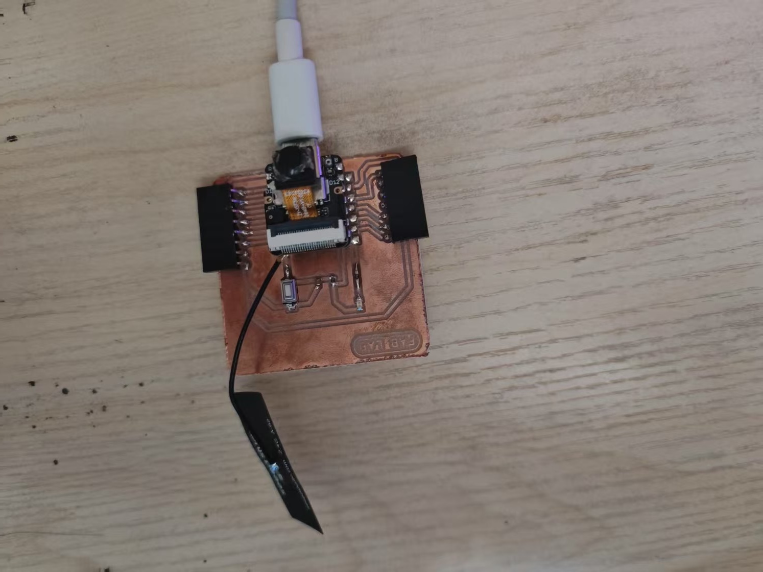
The program captures audio and records it to an SD card.
All project code is open-source and available at the following link: Microphone Recording Example Code
#include <stdio.h>
#include <string.h>
#include <math.h>
#include <sys/unistd.h>
#include <sys/stat.h>
#include "sdkconfig.h"
#include "esp_log.h"
#include "esp_err.h"
#include "esp_system.h"
#include "esp_vfs_fat.h"
#include "freertos/FreeRTOS.h"
#include "freertos/task.h"
#include "driver/i2s_pdm.h"
#include "driver/gpio.h"
#include "driver/spi_common.h"
#include "sdmmc_cmd.h"
#include "format_wav.h"
#include "mbedtls/base64.h"

static const char *TAG = "pdm_rec_example";

#define SPI_DMA_CHAN   SPI_DMA_CH_AUTO
#define NUM_CHANNELS   (1) // For mono recording only!
#define SD_MOUNT_POINT "/sdcard"
#define SAMPLE_SIZE    (CONFIG_EXAMPLE_BIT_SAMPLE * 1024)
#define BYTE_RATE      (CONFIG_EXAMPLE_SAMPLE_RATE * (CONFIG_EXAMPLE_BIT_SAMPLE / 8)) * NUM_CHANNELS

// When testing SD and SPI modes, keep in mind that once the card has been
// initialized in SPI mode, it can not be reinitialized in SD mode without
// toggling power to the card.
sdmmc_host_t host = SDSPI_HOST_DEFAULT();
sdmmc_card_t *card;
i2s_chan_handle_t rx_handle = NULL;

static int16_t i2s_readraw_buff[SAMPLE_SIZE];
size_t bytes_read;
const int WAVE_HEADER_SIZE = 44;

void mount_sdcard(void)
{
    esp_err_t ret;
    // Options for mounting the filesystem.
    // If format_if_mount_failed is set to true, SD card will be partitioned and
    // formatted in case when mounting fails.
    esp_vfs_fat_sdmmc_mount_config_t mount_config = { .format_if_mount_failed = true, .max_files = 5, .allocation_unit_size = 8 * 1024 };
    ESP_LOGI(TAG, "Initializing SD card");

    spi_bus_config_t bus_cfg = {
        .mosi_io_num = CONFIG_EXAMPLE_SPI_MOSI_GPIO,
        .miso_io_num = CONFIG_EXAMPLE_SPI_MISO_GPIO,
        .sclk_io_num = CONFIG_EXAMPLE_SPI_SCLK_GPIO,
        .quadwp_io_num = -1,
        .quadhd_io_num = -1,
        .max_transfer_sz = 4000,
    };
    ret = spi_bus_initialize(host.slot, &bus_cfg, SPI_DMA_CHAN);
    if (ret != ESP_OK)
    {
        ESP_LOGE(TAG, "Failed to initialize bus.");
        return;
    }

    // This initializes the slot without card detect (CD) and write protect (WP) signals.
    // Modify slot_config.gpio_cd and slot_config.gpio_wp if your board has these signals.
    sdspi_device_config_t slot_config = SDSPI_DEVICE_CONFIG_DEFAULT();
    slot_config.gpio_cs = CONFIG_EXAMPLE_SPI_CS_GPIO;
    slot_config.host_id = host.slot;

    ret = esp_vfs_fat_sdspi_mount(SD_MOUNT_POINT, &host, &slot_config, &mount_config, &card);

    if (ret != ESP_OK)
    {
        if (ret == ESP_FAIL)
        {
            ESP_LOGE(TAG, "Failed to mount filesystem.");
        }
        else
        {
            ESP_LOGE(TAG,
                "Failed to initialize the card (%s). "
                "Make sure SD card lines have pull-up resistors in place.",
                esp_err_to_name(ret));
        }
        return;
    }

    // Card has been initialized, print its properties
    sdmmc_card_print_info(stdout, card);
}

void record_wav(uint32_t rec_time)
{
    // Use POSIX and C standard library functions to work with files.
    int flash_wr_size = 0;
    ESP_LOGI(TAG, "Opening file");

    uint32_t flash_rec_time = BYTE_RATE * rec_time;
    const wav_header_t wav_header = WAV_HEADER_PCM_DEFAULT(flash_rec_time, 16, CONFIG_EXAMPLE_SAMPLE_RATE, 1);

    // First check if file exists before creating a new file.
    struct stat st;
    if (stat(SD_MOUNT_POINT "/record.wav", &st) == 0)
    {
        // Delete it if it exists
        unlink(SD_MOUNT_POINT "/record.wav");
    }

    // Create new WAV file
    FILE *f = fopen(SD_MOUNT_POINT "/record.wav", "a");
    if (f == NULL)
    {
        ESP_LOGE(TAG, "Failed to open file for writing");
        return;
    }

    // Write the header to the WAV file
    fwrite(&wav_header, sizeof(wav_header), 1, f);

    uint8_t *pcm_buff = malloc(128*1024);

    // Start recording
    while (flash_wr_size < flash_rec_time)
    {
        // Read the RAW samples from the microphone
        if (i2s_channel_read(rx_handle, (char *)i2s_readraw_buff, SAMPLE_SIZE, &bytes_read, 1000) == ESP_OK)
        {
            printf("%d [0] %d [1] %d [2] %d [3]%d ...\n",bytes_read, i2s_readraw_buff[0], i2s_readraw_buff[1], i2s_readraw_buff[2], i2s_readraw_buff[3]);
            memcpy(pcm_buff + flash_wr_size, i2s_readraw_buff, bytes_read);
            printf("[0] %d [1] %d [2] %d [3]%d...\n",pcm_buff[flash_wr_size], pcm_buff[flash_wr_size + 1], pcm_buff[flash_wr_size + 2], pcm_buff[flash_wr_size + 3]);
            // Write the samples to the WAV file
            fwrite(i2s_readraw_buff, bytes_read, 1, f);
            flash_wr_size += bytes_read;
        }
        else
        {
            printf("Read Failed!\n");
        }
    }

    uint8_t *base64_pcm = malloc(flash_wr_size * 2);
    size_t base64_size = 0;
    // Base64 encode the PCM data
    mbedtls_base64_encode(base64_pcm, flash_wr_size * 2, &base64_size, pcm_buff, flash_wr_size);
    base64_pcm[base64_size] = '\0';
    printf("Base64 encoded PCM data %d: %d\n",base64_size, flash_wr_size);
    printf("%s\n", base64_pcm);

    ESP_LOGI(TAG, "Recording done!");
    fclose(f);
    ESP_LOGI(TAG, "File written on SDCard");

    // All done, unmount partition and disable SPI peripheral
    esp_vfs_fat_sdcard_unmount(SD_MOUNT_POINT, card);
    ESP_LOGI(TAG, "Card unmounted");
    // Deinitialize the bus after all devices are removed
    spi_bus_free(host.slot);
}

void init_microphone(void)
{
    i2s_chan_config_t chan_cfg = I2S_CHANNEL_DEFAULT_CONFIG(I2S_NUM_AUTO, I2S_ROLE_MASTER);
    ESP_ERROR_CHECK(i2s_new_channel(&chan_cfg, NULL, &rx_handle));

    i2s_pdm_rx_config_t pdm_rx_cfg = {
        .clk_cfg = I2S_PDM_RX_CLK_DEFAULT_CONFIG(CONFIG_EXAMPLE_SAMPLE_RATE),
        /* The default mono slot is the left slot (whose 'select pin' of the PDM microphone is pulled down) */
        .slot_cfg = I2S_PDM_RX_SLOT_DEFAULT_CONFIG(I2S_DATA_BIT_WIDTH_16BIT, I2S_SLOT_MODE_MONO),
        .gpio_cfg = {
            .clk = CONFIG_EXAMPLE_I2S_CLK_GPIO,
            .din = CONFIG_EXAMPLE_I2S_DATA_GPIO,
            .invert_flags = {
                .clk_inv = false,
            },
        },
    };
    ESP_ERROR_CHECK(i2s_channel_init_pdm_rx_mode(rx_handle, &pdm_rx_cfg));
    ESP_ERROR_CHECK(i2s_channel_enable(rx_handle));
}

void app_main(void)
{
    printf("PDM microphone recording example start\n--------------------------------------\n");
    // Mount the SDCard for recording the audio file
    mount_sdcard();
    // Acquire a I2S PDM channel for the PDM digital microphone
    init_microphone();
    ESP_LOGI(TAG, "Starting recording for %d seconds!", CONFIG_EXAMPLE_REC_TIME);
    // Start Recording
    record_wav(CONFIG_EXAMPLE_REC_TIME);
    // Stop I2S driver and destroy
    ESP_ERROR_CHECK(i2s_channel_disable(rx_handle));
    ESP_ERROR_CHECK(i2s_del_channel(rx_handle));
}
Flash the program to the XIAO ESP32S3:
idf.py build
idf.py flash
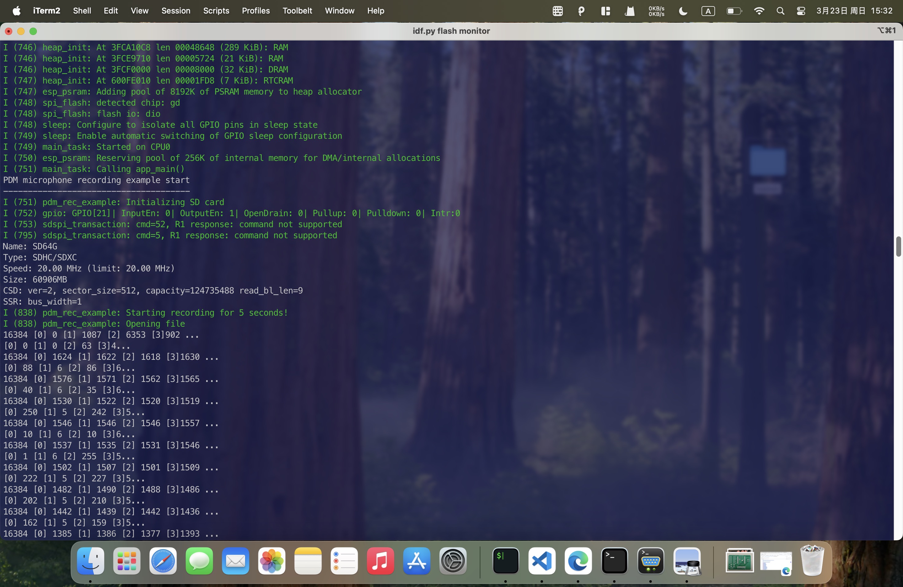
Finally, Get the recorded audio file from the SD card.
Download audio1.3 Accelerometer
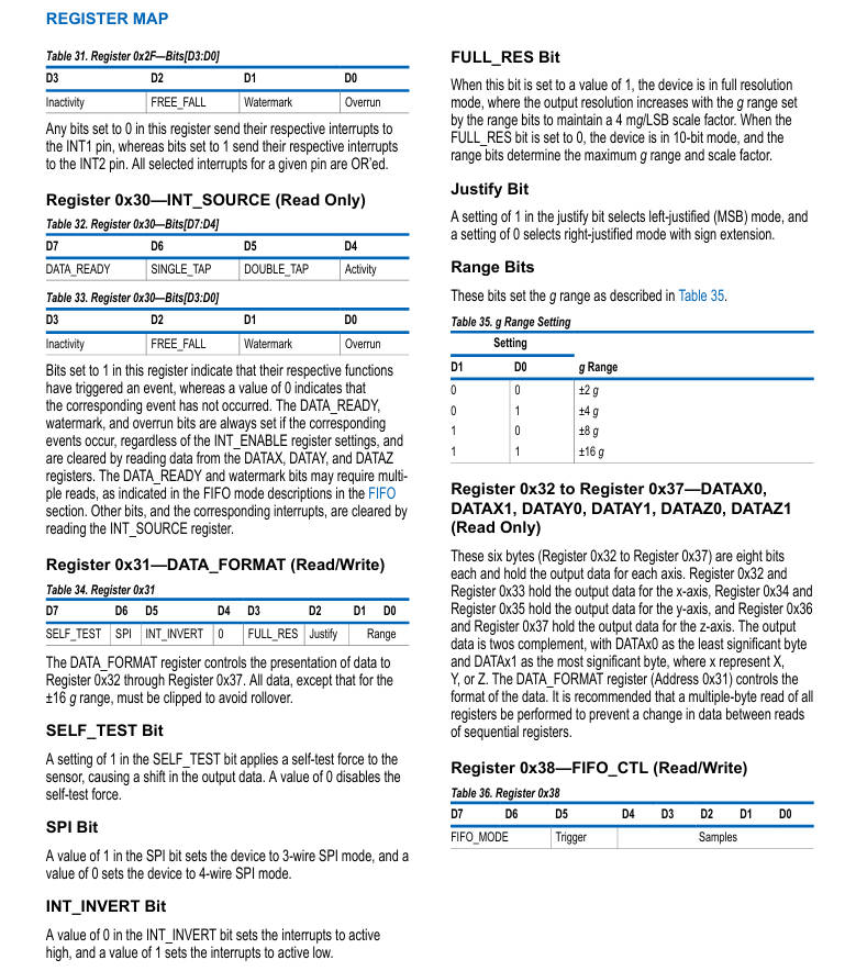
In my project, I have integrated a accelerometer. It is an LIS3DH sensor, which features an I2C interface and requires the following pins:
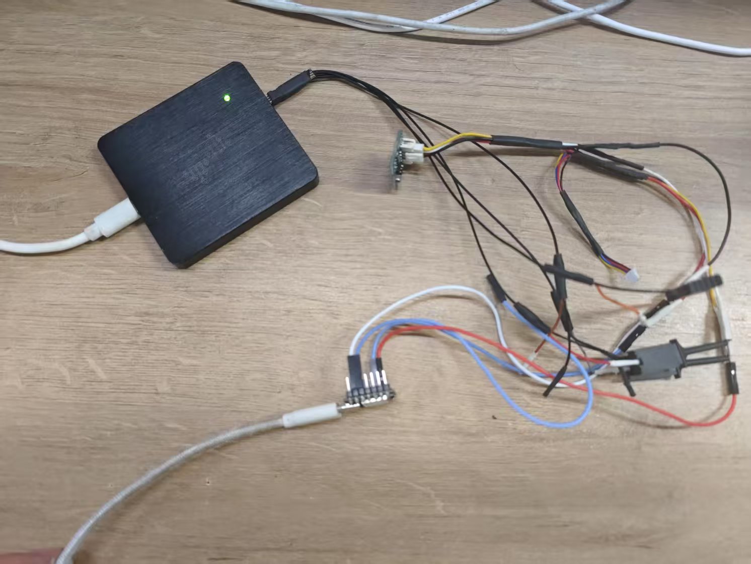
Mission Objectives
- Establish I2C communication between XIAO ESP32S3 and ADXL345L
- Capture I2C protocol waveforms using logic analyzer
- Parse data from 0x32 start register to obtain 3-axis acceleration values
ADXL345L Technical Specifications
Core Parameters
| Parameter | Specification |
|---|---|
| Communication Protocol | I2C/SPI (I2C used) |
| Measurement Range | ±2g/±4g/±8g/±16g |
| Resolution (±2g) | 4mg/LSB |
| Output Data Rate | 0.1Hz - 3200Hz |
| Operating Voltage | 2.0V - 3.6V |
| I2C Address | 0x53 (SDO=GND) |
Register Configuration
• 0x32: X-axis low byte (X0)
• 0x33: X-axis high byte (X1)
• 0x34: Y-axis low byte (Y0)
• 0x35: Y-axis high byte (Y1)
• 0x36: Z-axis low byte (Z0)
• 0x37: Z-axis high byte (Z1)
Hardware Connection Guide
1. XIAO ESP32S3 ↔ ADXL345L Wiring
| ADXL345L Pin | XIAO ESP32S3 Pin |
|---|---|
| VCC | 3.3V |
| GND | GND |
| SDA | D4 (I2C_SDA) |
| SCL | D5 (I2C_SCL) |
| SDO | GND (Address 0x53) |
2. Logic Analyzer Connection
| Analyzer Channel | Connection Point |
|---|---|
| CH0 | SDA (White wire) |
| CH1 | SCL (Red wire) |
| GND | Board GND |
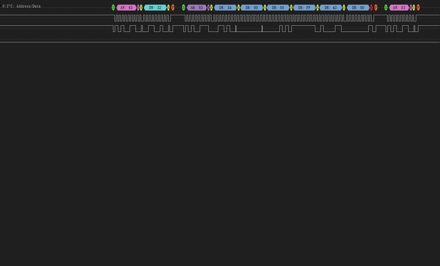
Connect ADXL345L to XIAO ESP32S3 with logic analyzer
Software Implementation
1. Arduino Code Framework
#include <Wire.h>
#include <ADXL345.h>

ADXL345 adxl; //variable adxl is an instance of the ADXL345 library

void setup() {
    Serial.begin(9600);
    adxl.powerOn();

    //set activity/ inactivity thresholds (0-255)
    adxl.setActivityThreshold(75); //62.5mg per increment
    adxl.setInactivityThreshold(75); //62.5mg per increment
    adxl.setTimeInactivity(10); // how many seconds of no activity is inactive?

    //look of activity movement on this axes - 1 == on; 0 == off
    adxl.setActivityX(1);
    adxl.setActivityY(1);
    adxl.setActivityZ(1);

    //look of inactivity movement on this axes - 1 == on; 0 == off
    adxl.setInactivityX(1);
    adxl.setInactivityY(1);
    adxl.setInactivityZ(1);

    //look of tap movement on this axes - 1 == on; 0 == off
    adxl.setTapDetectionOnX(0);
    adxl.setTapDetectionOnY(0);
    adxl.setTapDetectionOnZ(1);

    //set values for what is a tap, and what is a double tap (0-255)
    adxl.setTapThreshold(50); //62.5mg per increment
    adxl.setTapDuration(15); //625us per increment
    adxl.setDoubleTapLatency(80); //1.25ms per increment
    adxl.setDoubleTapWindow(200); //1.25ms per increment

    //set values for what is considered freefall (0-255)
    adxl.setFreeFallThreshold(7); //(5 - 9) recommended - 62.5mg per increment
    adxl.setFreeFallDuration(45); //(20 - 70) recommended - 5ms per increment

    //setting all interrupts to take place on int pin 1
    //I had issues with int pin 2, was unable to reset it
    adxl.setInterruptMapping(ADXL345_INT_SINGLE_TAP_BIT,   ADXL345_INT1_PIN);
    adxl.setInterruptMapping(ADXL345_INT_DOUBLE_TAP_BIT,   ADXL345_INT1_PIN);
    adxl.setInterruptMapping(ADXL345_INT_FREE_FALL_BIT,    ADXL345_INT1_PIN);
    adxl.setInterruptMapping(ADXL345_INT_ACTIVITY_BIT,     ADXL345_INT1_PIN);
    adxl.setInterruptMapping(ADXL345_INT_INACTIVITY_BIT,   ADXL345_INT1_PIN);

    //register interrupt actions - 1 == on; 0 == off
    adxl.setInterrupt(ADXL345_INT_SINGLE_TAP_BIT, 1);
    adxl.setInterrupt(ADXL345_INT_DOUBLE_TAP_BIT, 1);
    adxl.setInterrupt(ADXL345_INT_FREE_FALL_BIT,  1);
    adxl.setInterrupt(ADXL345_INT_ACTIVITY_BIT,   1);
    adxl.setInterrupt(ADXL345_INT_INACTIVITY_BIT, 1);
}

void loop() {

    //Boring accelerometer stuff
    int x, y, z;
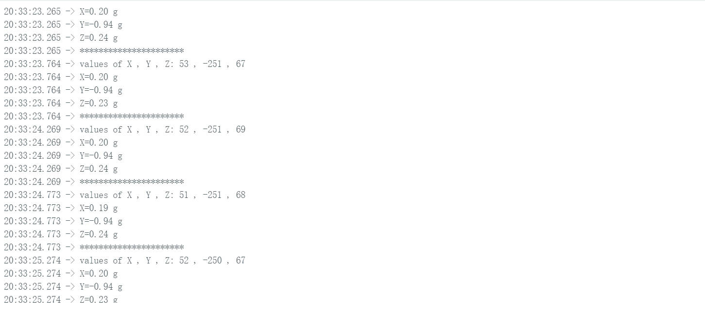
    adxl.readXYZ(&x, &y, &z); //read the accelerometer values and store them in variables  x,y,z
    // Output x,y,z values
    Serial.print("values of X , Y , Z: ");
    Serial.print(x);
    Serial.print(" , ");
    Serial.print(y);
    Serial.print(" , ");
    Serial.println(z);

    double xyz[3];
    double ax, ay, az;
    adxl.getAcceleration(xyz);
    ax = xyz[0];
    ay = xyz[1];
    az = xyz[2];
    Serial.print("X=");
    Serial.print(ax);
    Serial.println(" g");
    Serial.print("Y=");
    Serial.print(ay);
    Serial.println(" g");
    Serial.print("Z=");
    Serial.print(az);
    Serial.println(" g");
    Serial.println("**********************");
    delay(500);

}
Logic Analyzer Verification
1. Typical I2C Communication Waveform
I2C protocol capture for axis data reading
Waveform Characteristics
• Start Condition: SDA falls while SCL high
• Address Frame: 0x53 (7-bit address + R/W bit)
• Register Write: 0x32 start address
• Data Read: 6-byte continuous read (ACK after each byte)
2. Data Parsing Validation
| Register | Raw Value (HEX) | Calculation | Acceleration (g) |
|---|---|---|---|
| 0x32 (X0) | 0x34 | 52 × 0.00376390 | +0.1957g |
| 0x33 (X1) | 0x00 | ||
| 0x34 (Y0) | 0x05 | -251 × 0.00376009 | -0.9438g |
| 0x35 (Y1) | 0xFF | ||
| 0x36 (Z0) | 0x43 | 67 × 0.00349265 | +0.2340g |
| 0x37 (Z1) | 0x00 |
1.4 Mositure Sensor
I connected the moisture sensor to the Board I designed at week 6.
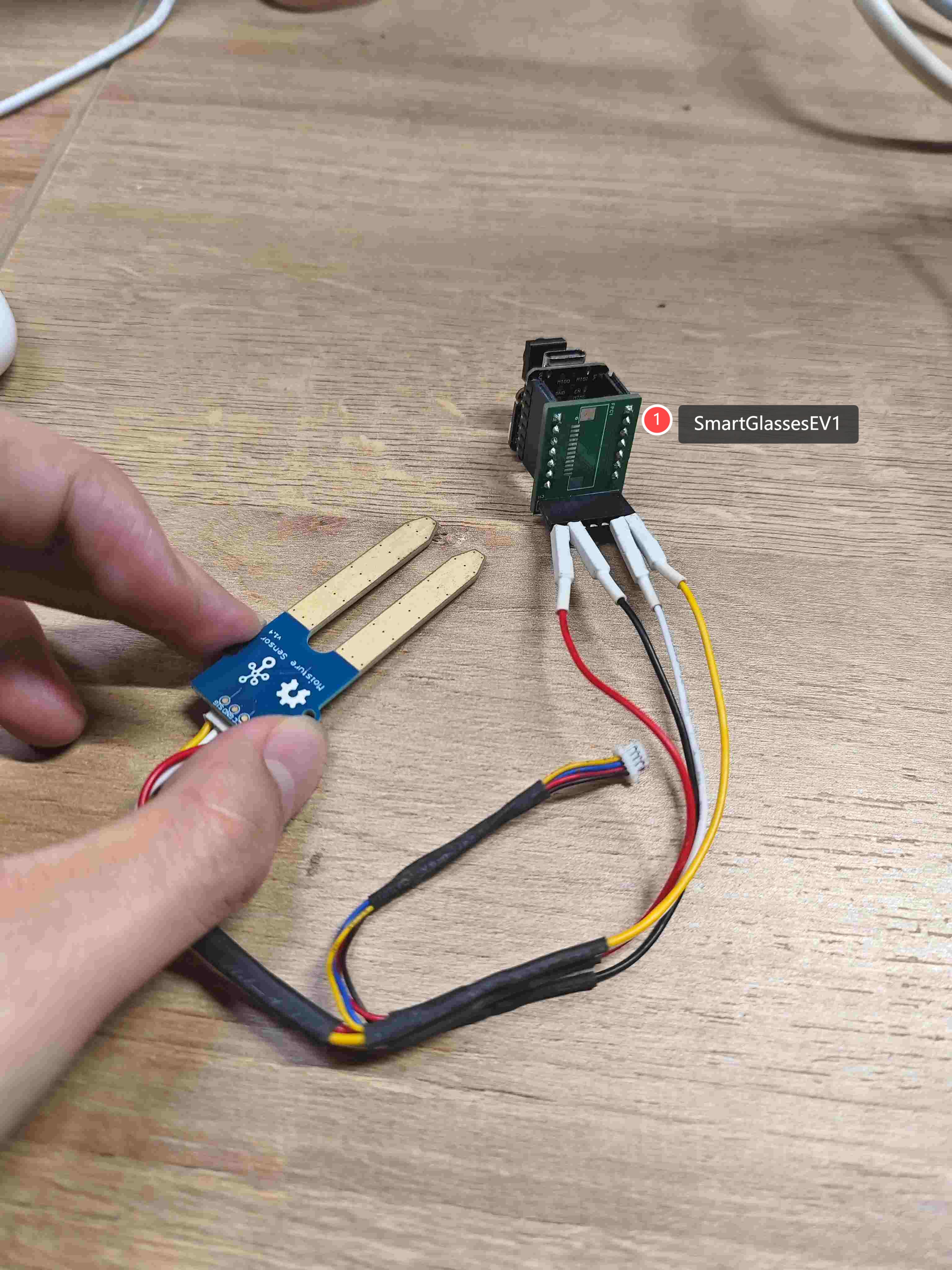
Hardware Connection Guide
1. XIAO ESP32S3 ↔ SmartGlassesEV1 ↔ ADXL345L Wiring
| ADXL345L Pin | XIAO ESP32S3 Pin |
|---|---|
| VCC | 3.3V |
| GND | GND |
| SIG | A0 |
2. Measure the Connection
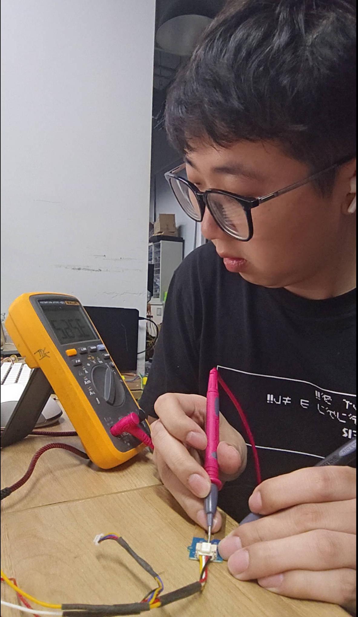
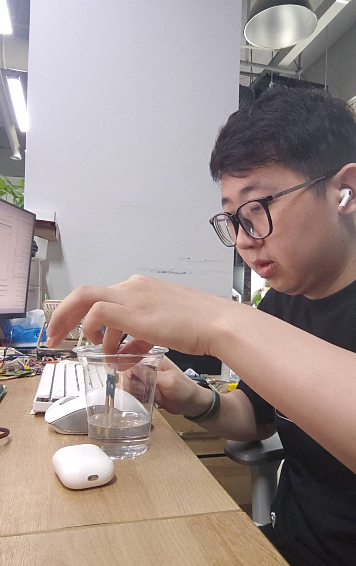
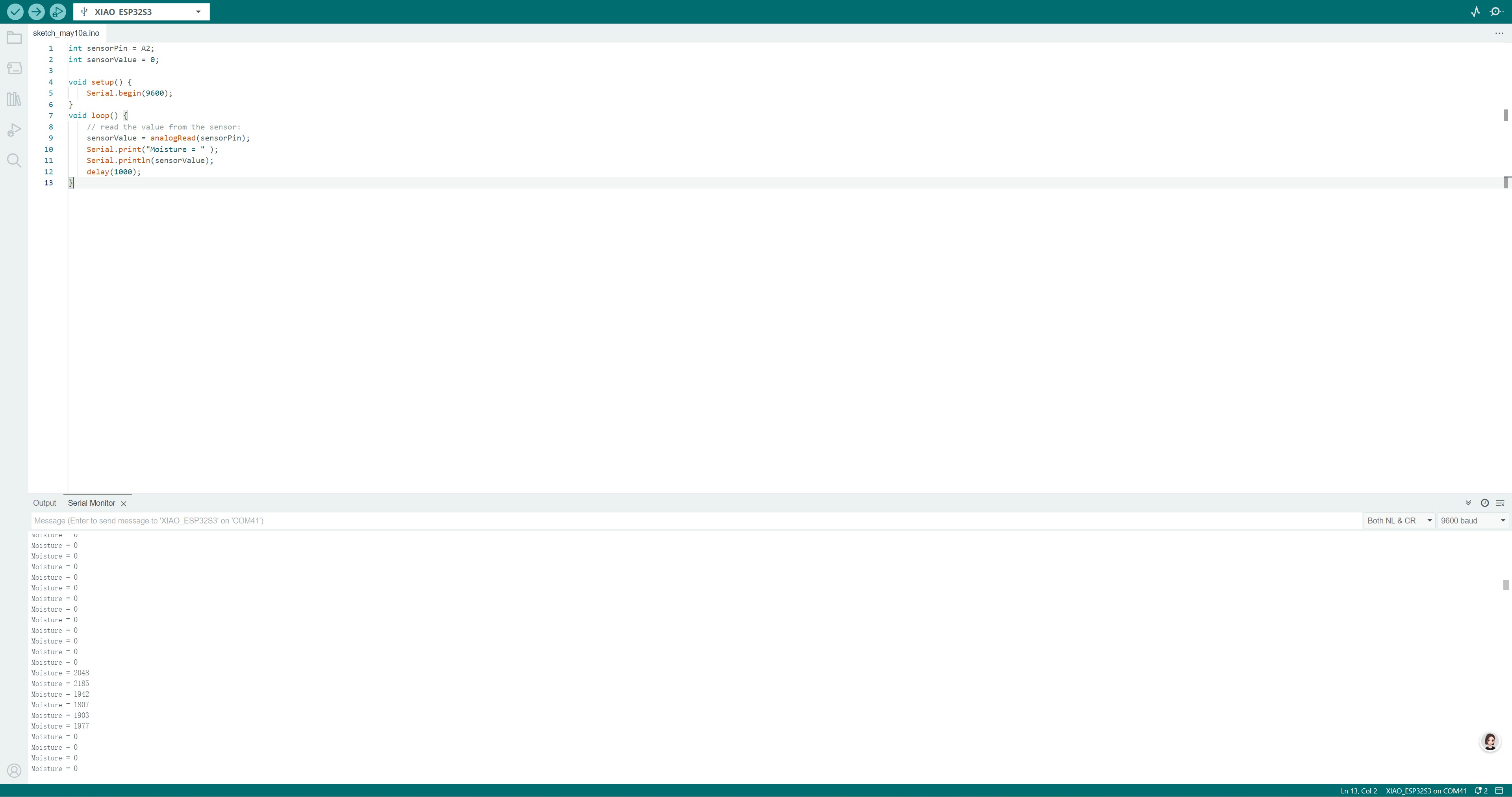
3. Measure the Moisture Level
Put the moisture sensor on the water surface, the voltage of the sensor will decrease.
1.5 Resources
All project code is open-source and available at the following links: