2. Hardware
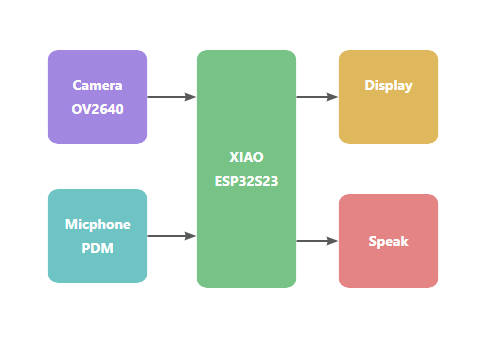
2.1 System block diagram
- Core Control Layer: The Seeed Studio XIAO ESP32S3 serves as the main control unit, utilizing its dual-core 240 MHz processor to achieve multitasking scheduling.
- Audio Processing Layer: The MAX9857 Class D amplifier delivers 3W stereo output and receives audio data via the I2S digital audio interface.
- Display Interaction Layer: A GC9107 0.85-inch LCD screen (128x128 RGB) provides a graphical interface via the SPI interface.
- User Input Layer: A capacitive touch button uses GPIO interrupts for detection and supports single-click and long-press event recognition.
- Status Indication Layer: An RGB LED achieves multicolor status indication through PWM dimming.
- Power Management Layer: Powered through a USB Type-C input, A 200mAh Li-ion battery provides power for the entire system.
2.2 Schematic
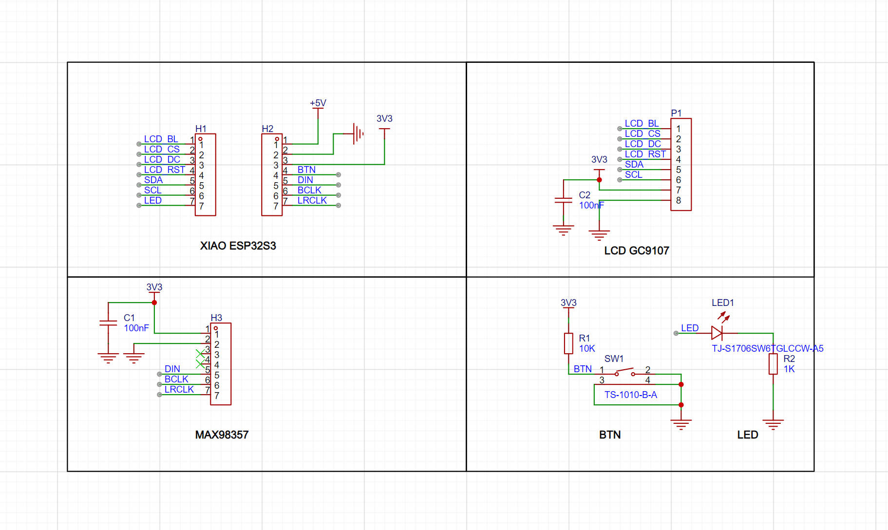
Main Control Interface Design:
-
I2S0 Bus: Connected to the MAX9857
- BCLK: D8
- WS: D7
- DATA: D9
-
SPI Bus: Drives the GC9107
- SCK: D6
- MOSI: D5
- CS: D1
- DC: D2
- BL (Backlight): D0
-
GPIO Multiplexing Configuration:
- Button: D9
- LED: D6
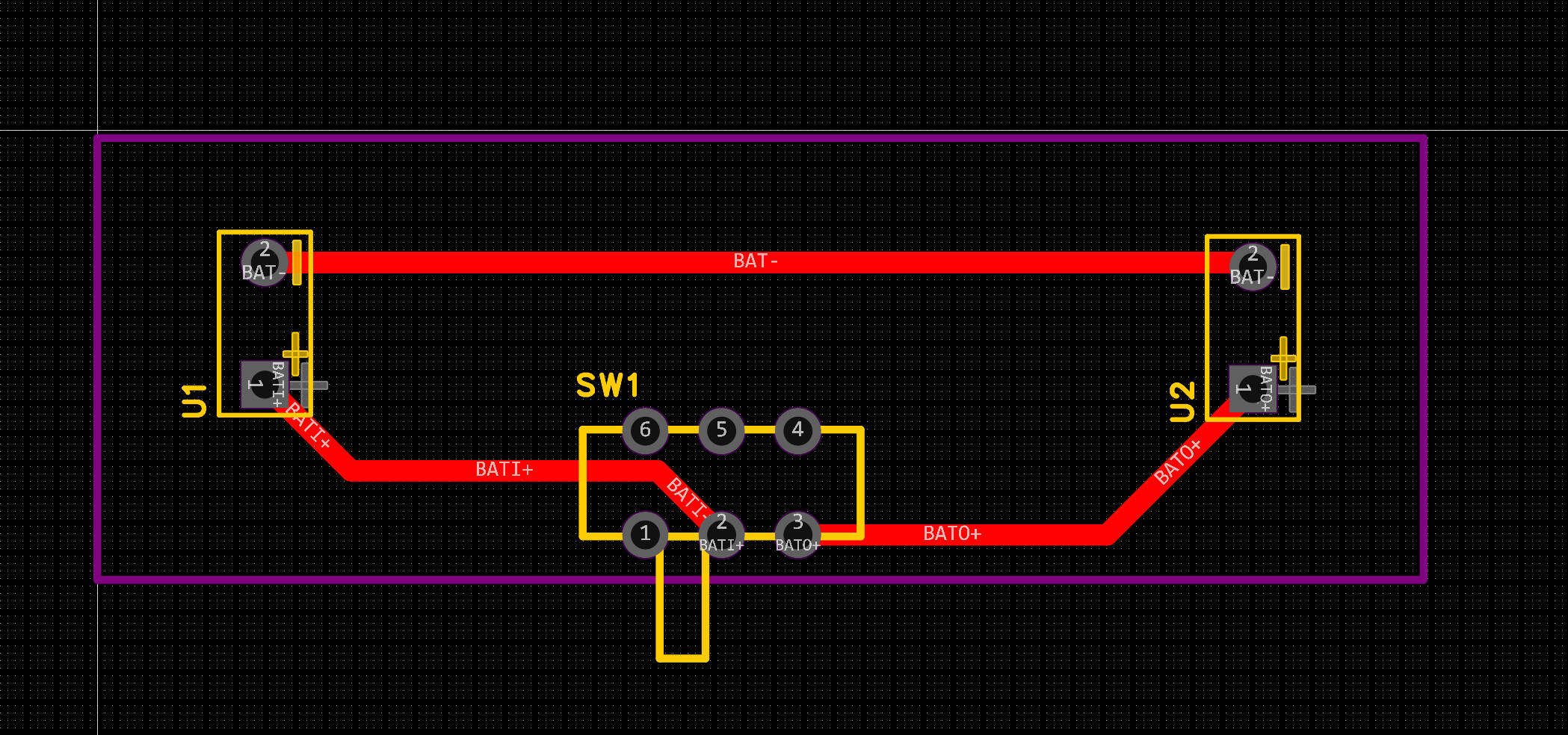
Key Circuit Designs:
-
Audio Power Amplification:
- MAX9857 uses differential output configuration (OUT+ / OUT-)
- 100nF decoupling capacitor array
-
Display Driver Optimization:
- 100nF decoupling capacitor array
-
Button Design:
- 10K pull-up resistor
-
LED Design:
- 1K pull-up resistor
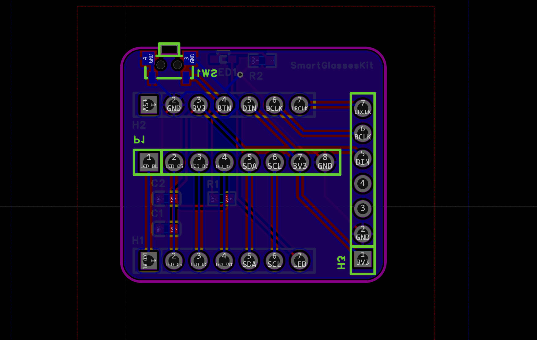
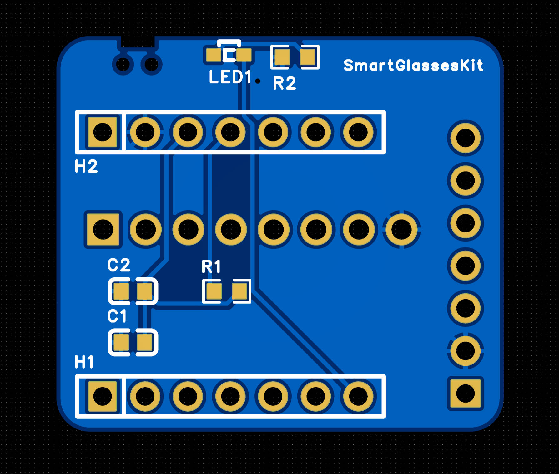
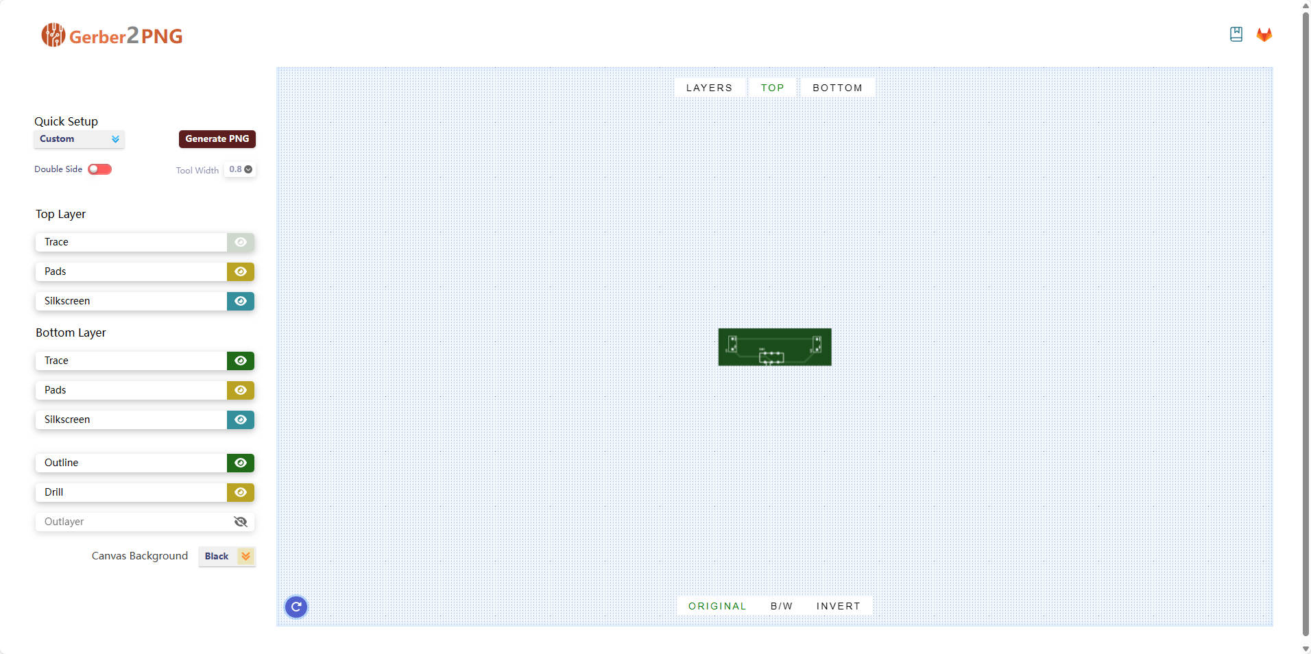
2.3 PCB
Button Cutout Design:
- A 2 mm keepout zone is added around the tactile button (SW1).
- Ground pour is removed under the button area.
- PCB edge clearance of 3 mm is reserved to allow button travel.
Layer Stackup:
-
2-layer board (1.6 mm FR4)
- Top Layer: Signal and power routing
- Bottom Layer: Continuous ground plane
Critical Component Placement:
- The audio amplifier (MAX9857) is isolated from digital components to minimize interference.
- The LCD connector is aligned with the board edge for easy assembly and accessibility.
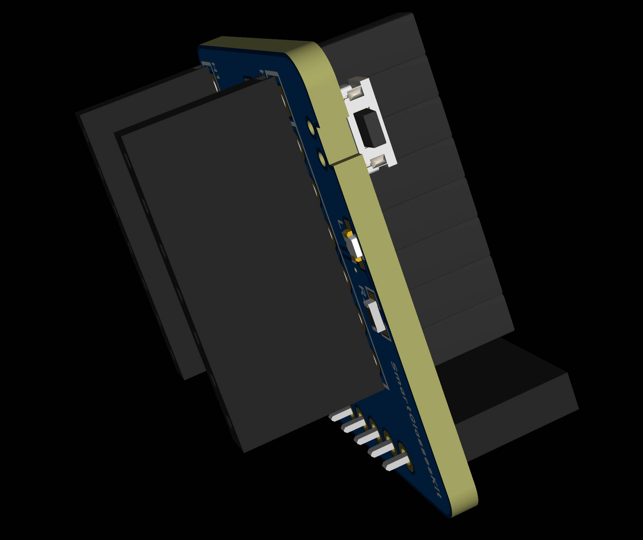
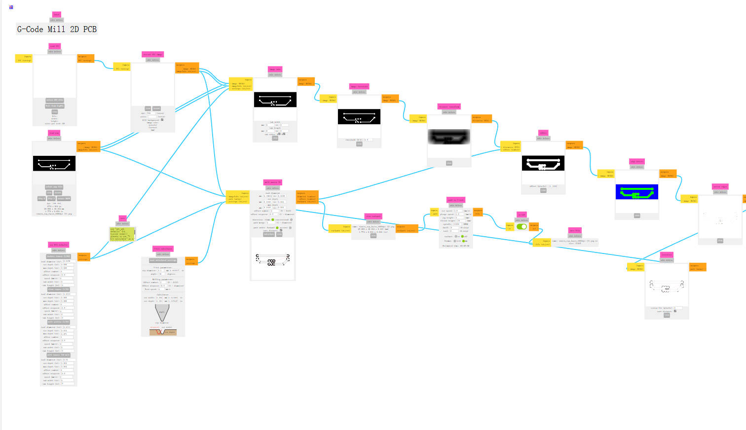
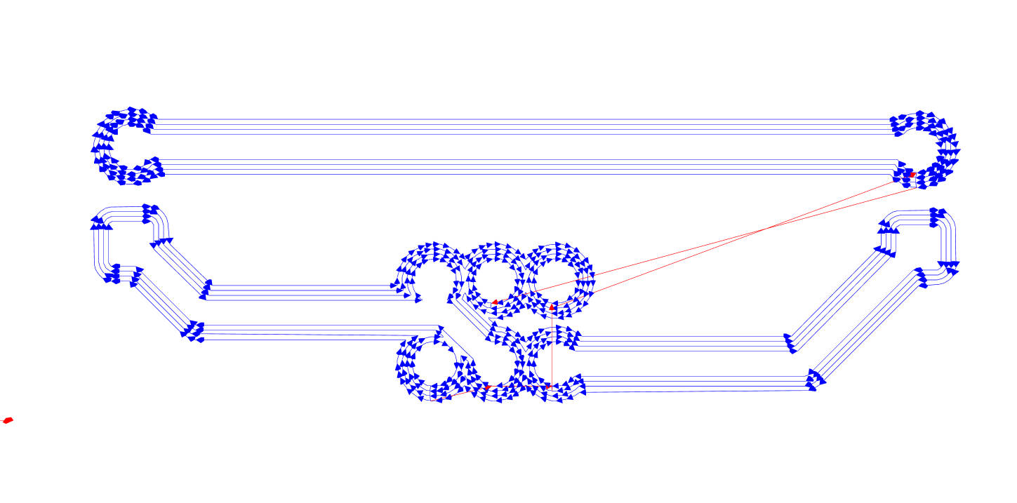
2.4 2D & 3D rendering
After the PCB is completed, the 2D and 3D rendering are done.

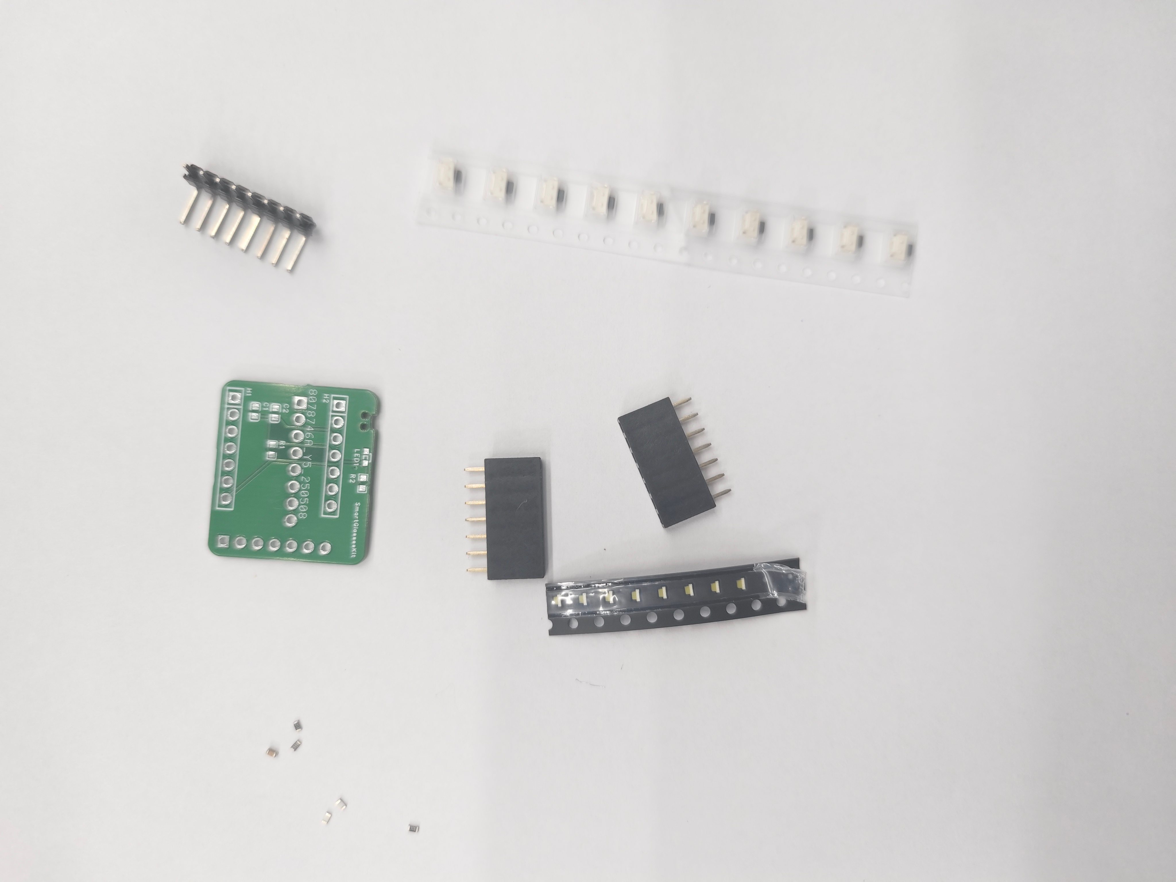
2.6 Product
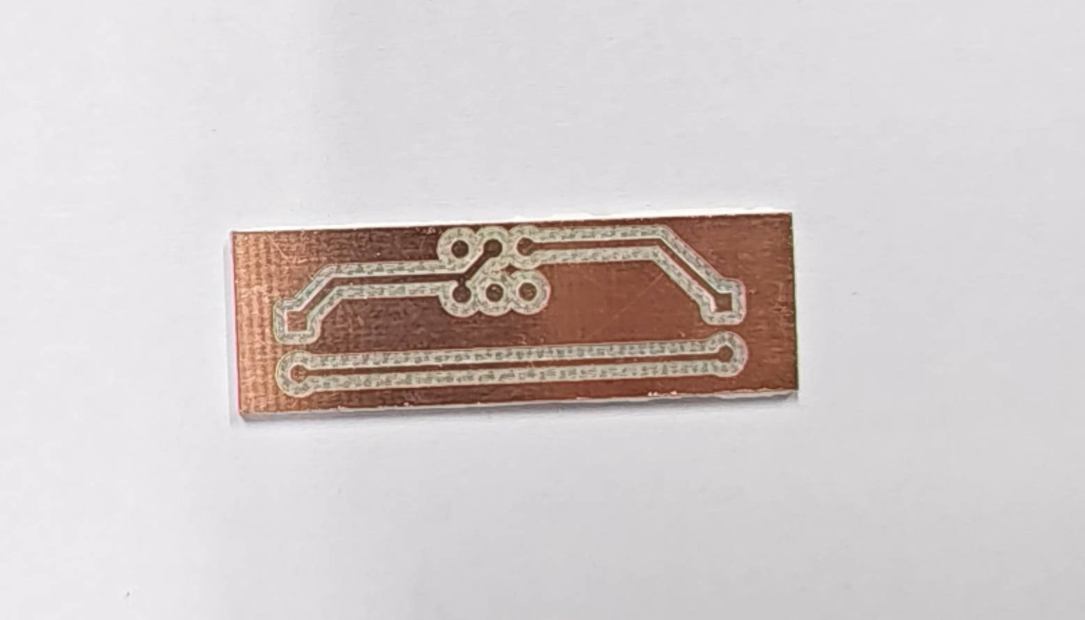
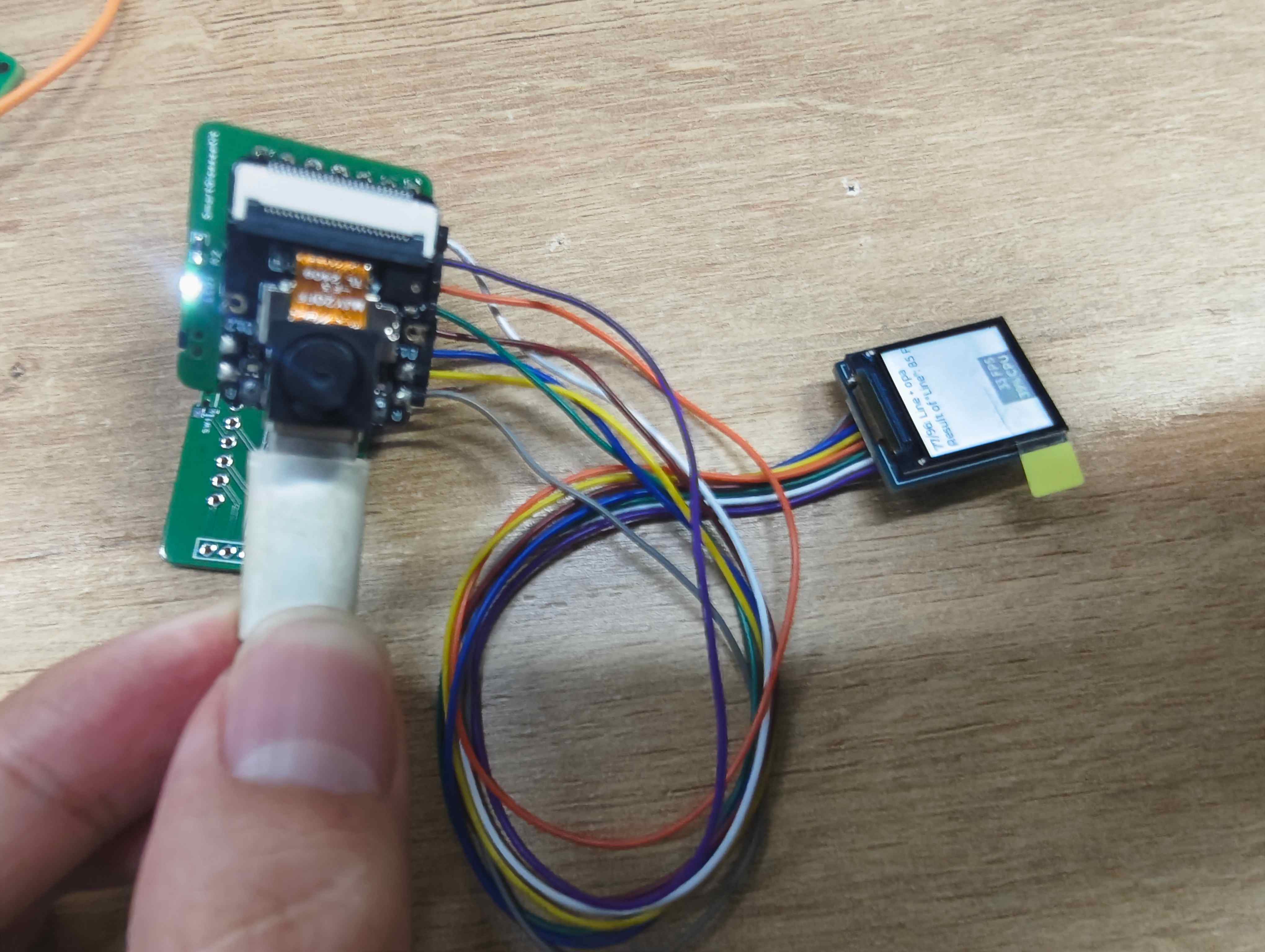
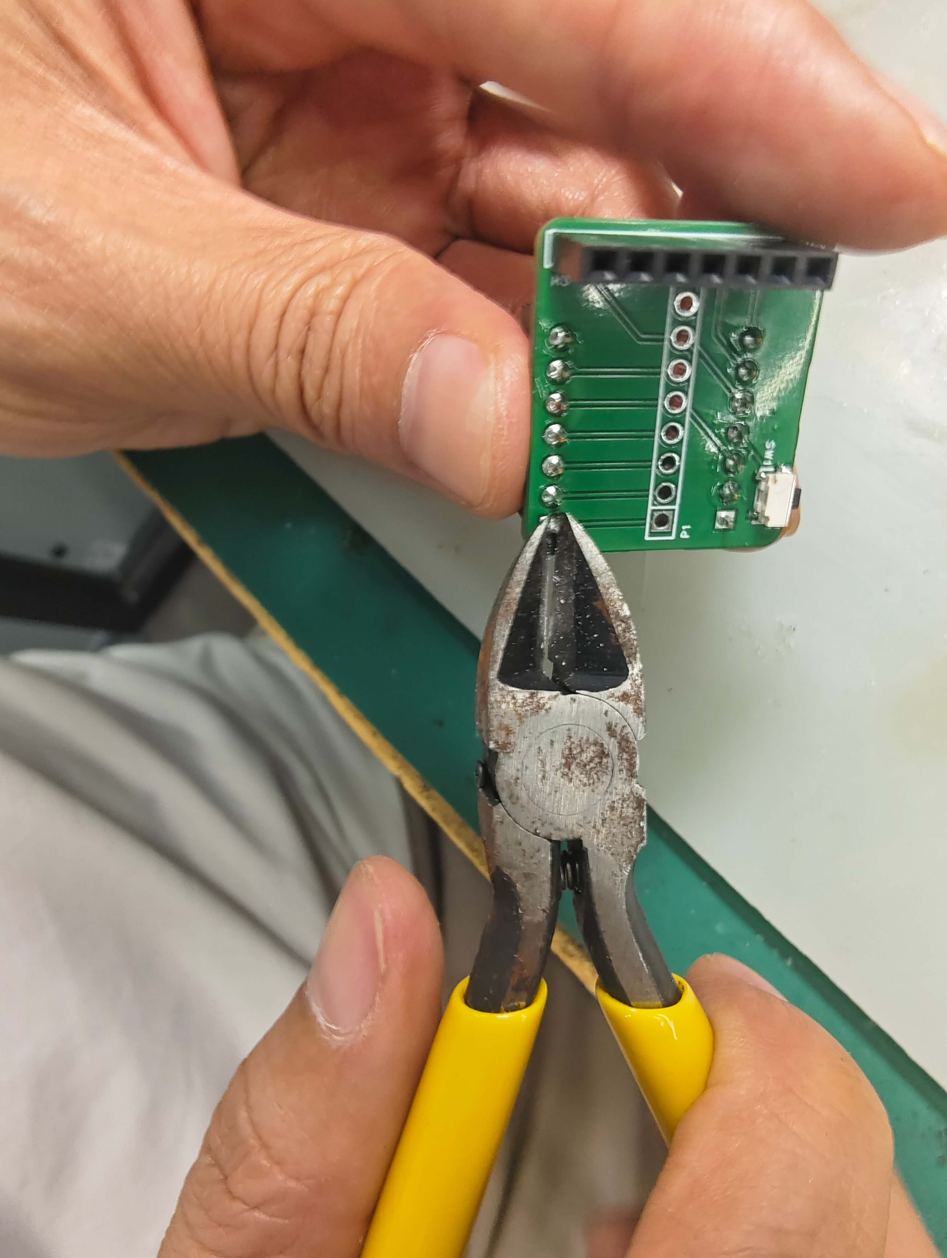
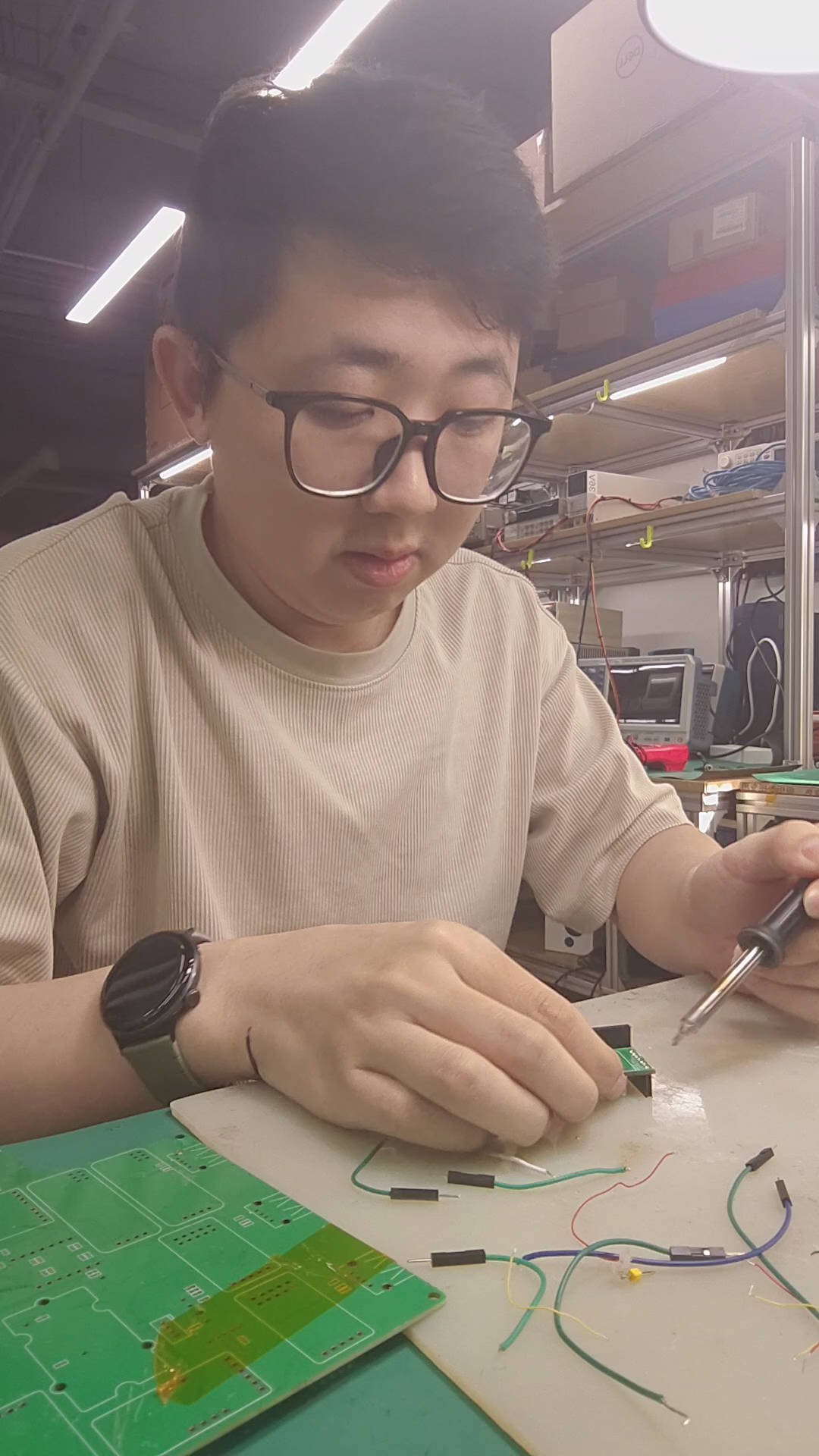
2.6 Soildering
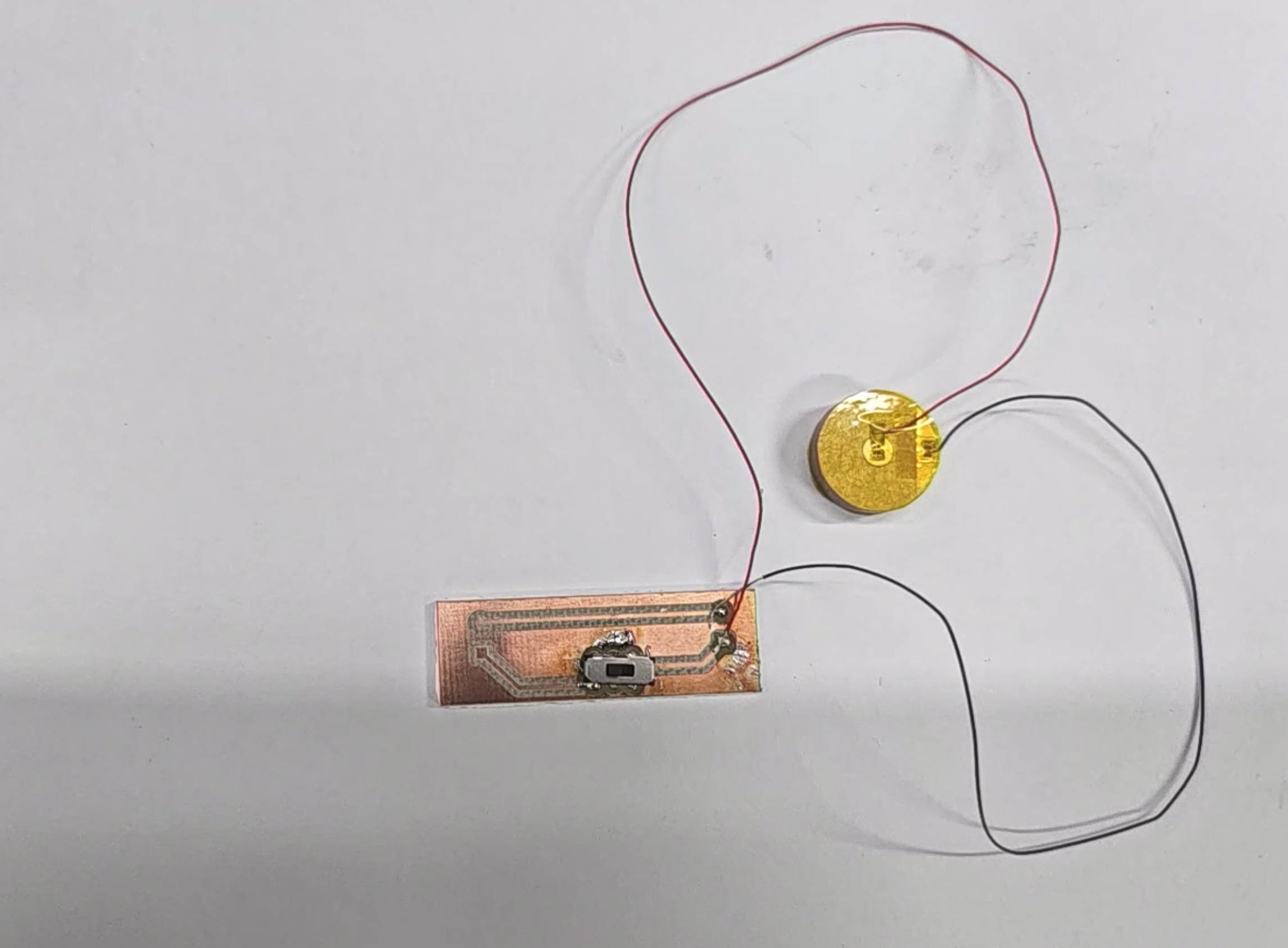
2.7 Testing