1. Design and 3D printing
This week, we will learn how to use 3D printing. I designed a Skeleton Cylinder OBJ model and printed it. Besides that, I also learned how to use 3D printing software to prepare the model for printing.
1.1 Design
I used FreeCAD to design a Skeleton Cylinder OBJ model, which can be used for various applications that require a cylindrical shape with specific cutouts and structural features.
1.1.1 Add Skeleton Cylinder Workbench
FreeCAD doesn't have a Skeleton Cylinder workbench by default. So, I need to add it manually by going to the workbench manager.
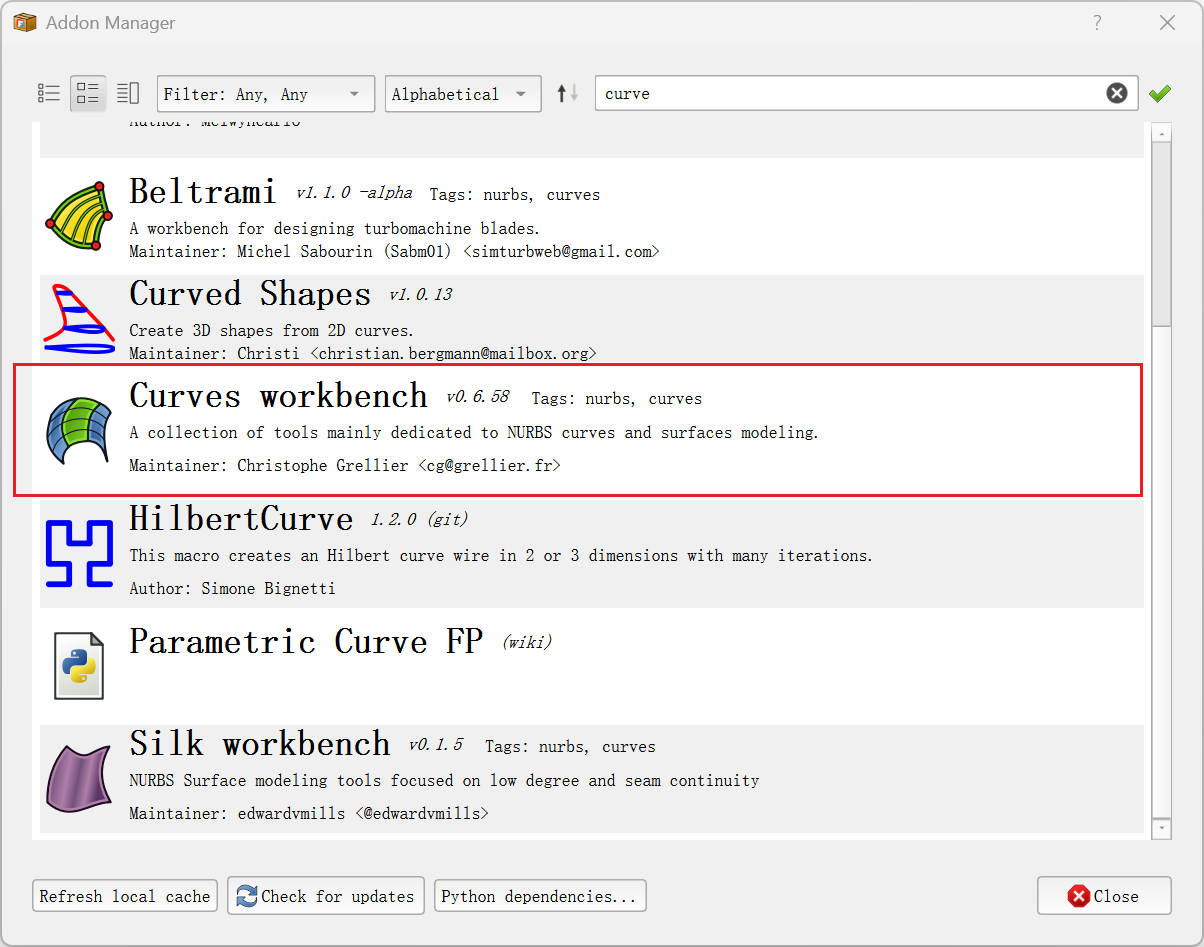
Screenshot showing the FreeCAD interface.
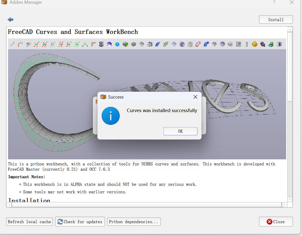
Instructions for adding the Skeleton Cylinder workbench in FreeCAD.
After adding the Skeleton Cylinder workbench, we need to restart FreeCAD, and then we can see the Skeleton Cylinder workbench listed in the workbench selection menu.

Once restarted, the Skeleton Cylinder workbench is ready to be used.
1.1.2 Design a Skeleton Cylinder model
- Create two concentric circles
- Radius: 10mm
- Radius: 6mm
These circles will form the base of the cylinder.
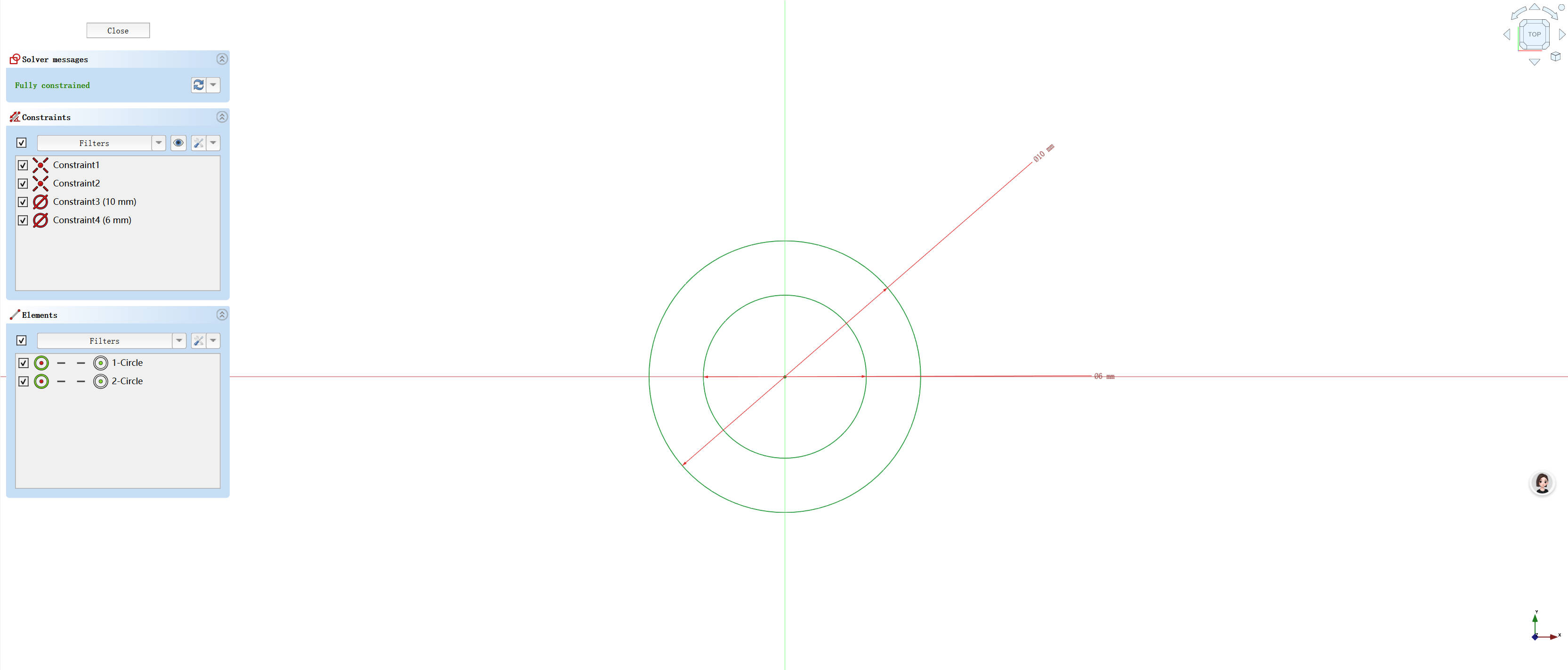
The two concentric circles that form the base.
- Pad the circle
- Pad 12mm
The pad operation extrudes the circle into a 3D shape.
- Pad 12mm
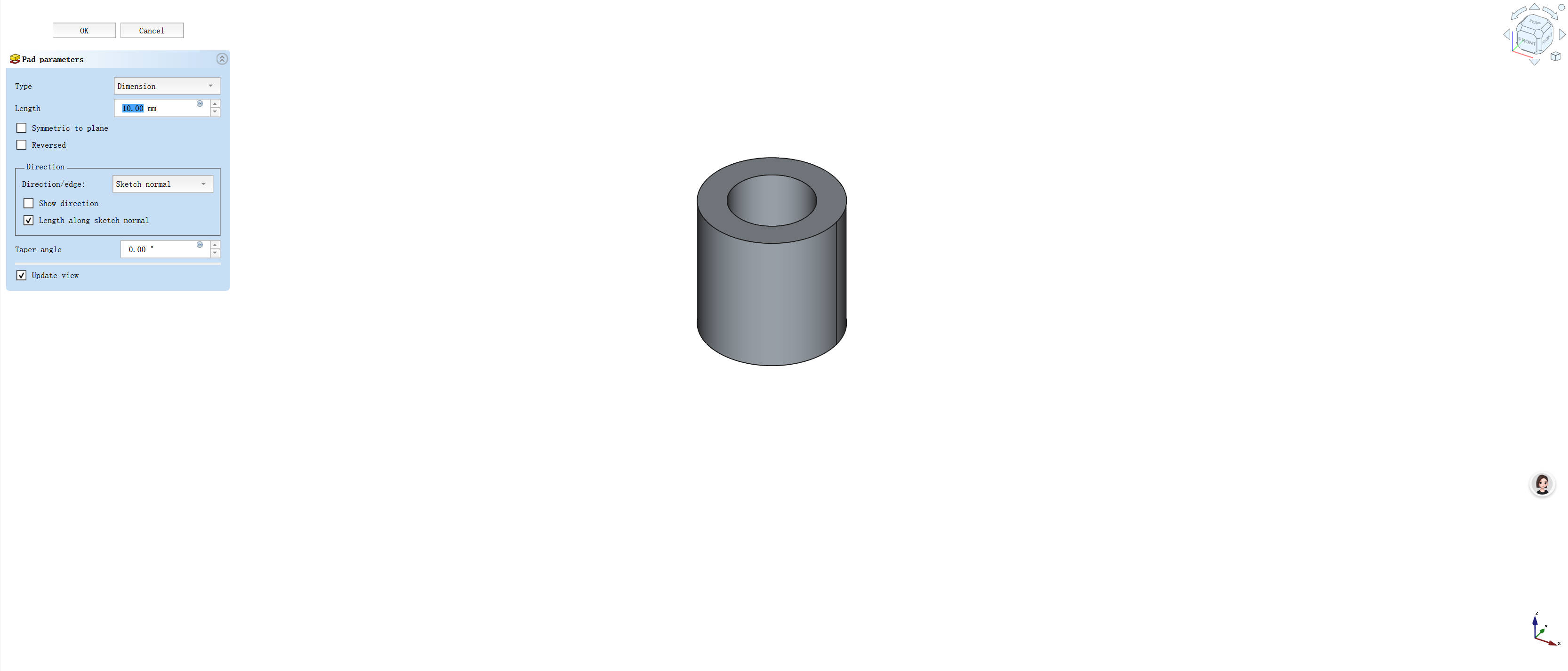
The 3D pad extruded from the concentric circles.
- Create a sketch on the Skeleton Cylinder surface
A new sketch is made on the surface of the padded cylinder to begin adding features like slots.
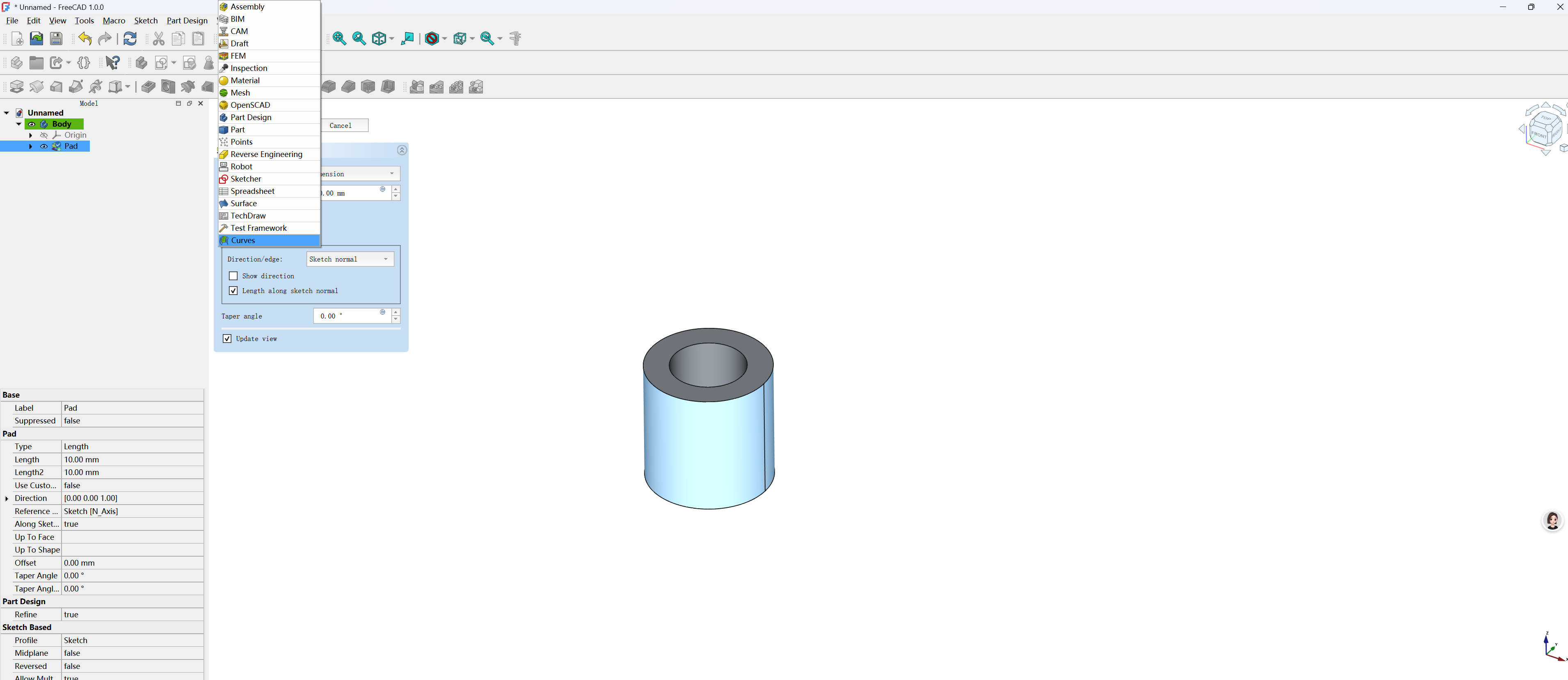
The sketch is drawn on the surface of the cylinder.
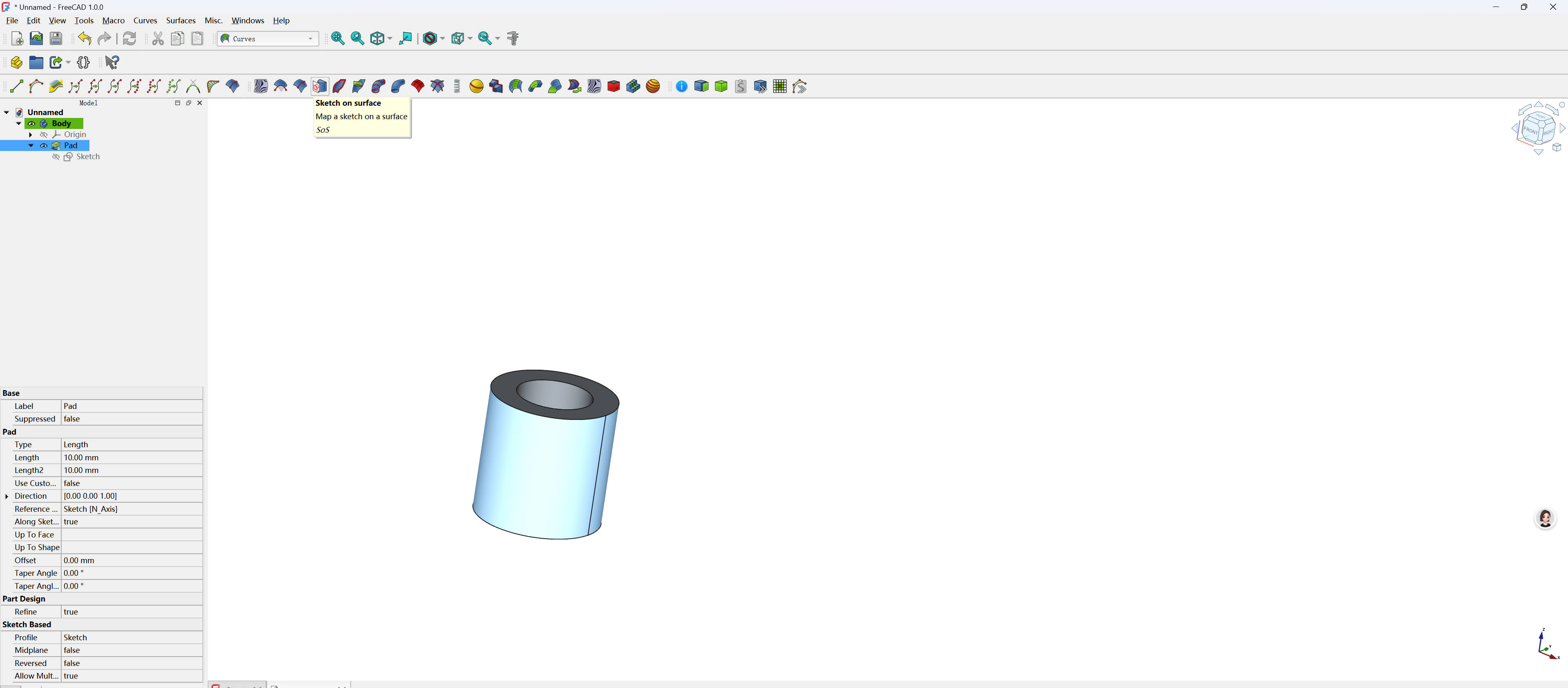
Close-up of the sketch on the surface of the Skeleton Cylinder.
After that, you can see the Skeleton Cylinder sketch ready for further modifications.
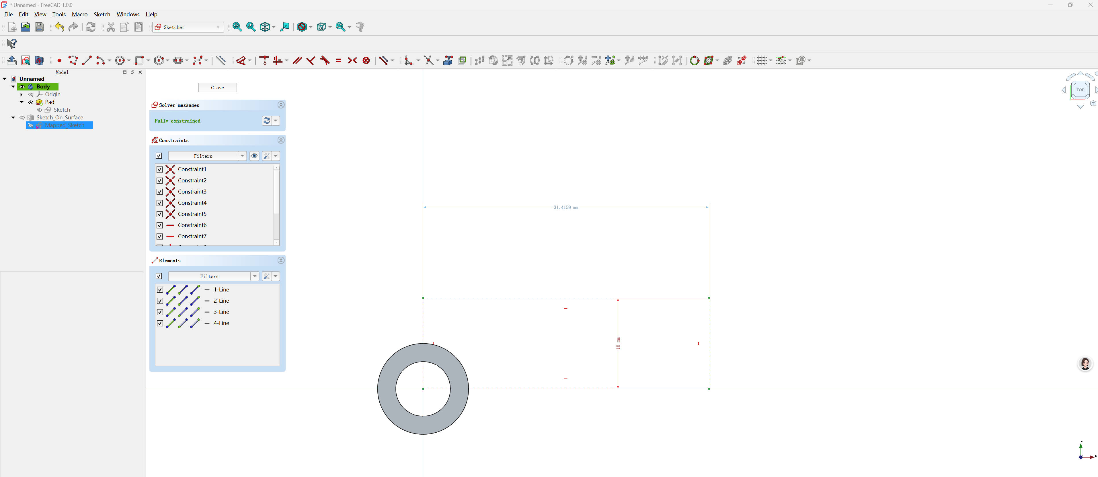
The completed sketch on the cylinder surface.
- Create a slot on the sketch
The slot will be added at a specific location on the sketch to further define the cylinder's geometry.
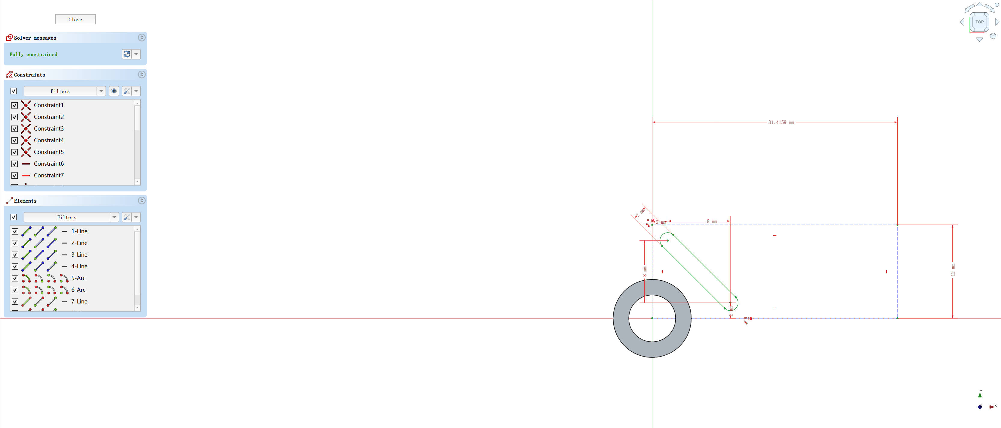
The slot is drawn on the sketch.
After closing the sketch, you can see the slot embedded on the surface of the Skeleton Cylinder.
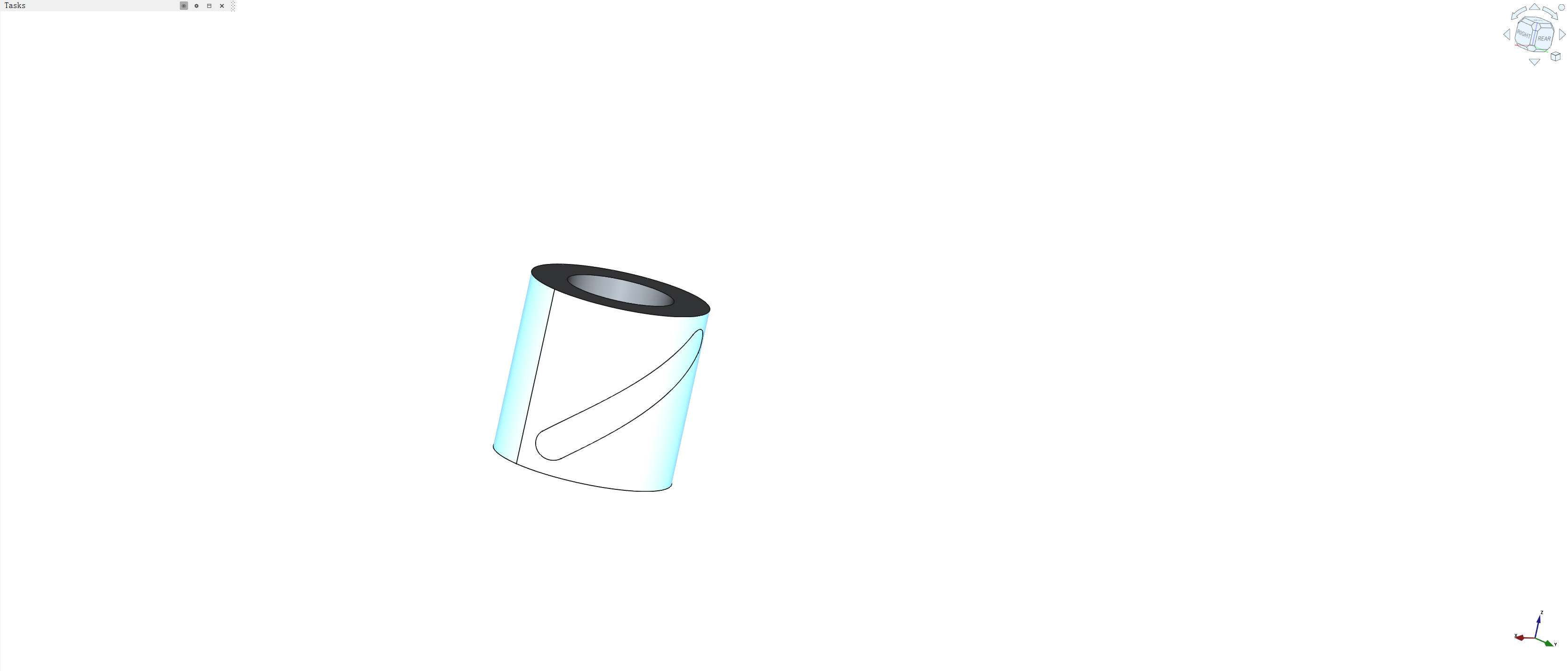
The slot appears on the surface of the Skeleton Cylinder after closing the sketch.
- Pad the slot
The pad operation is applied to the slot, creating a 3D feature that cuts through the cylinder.
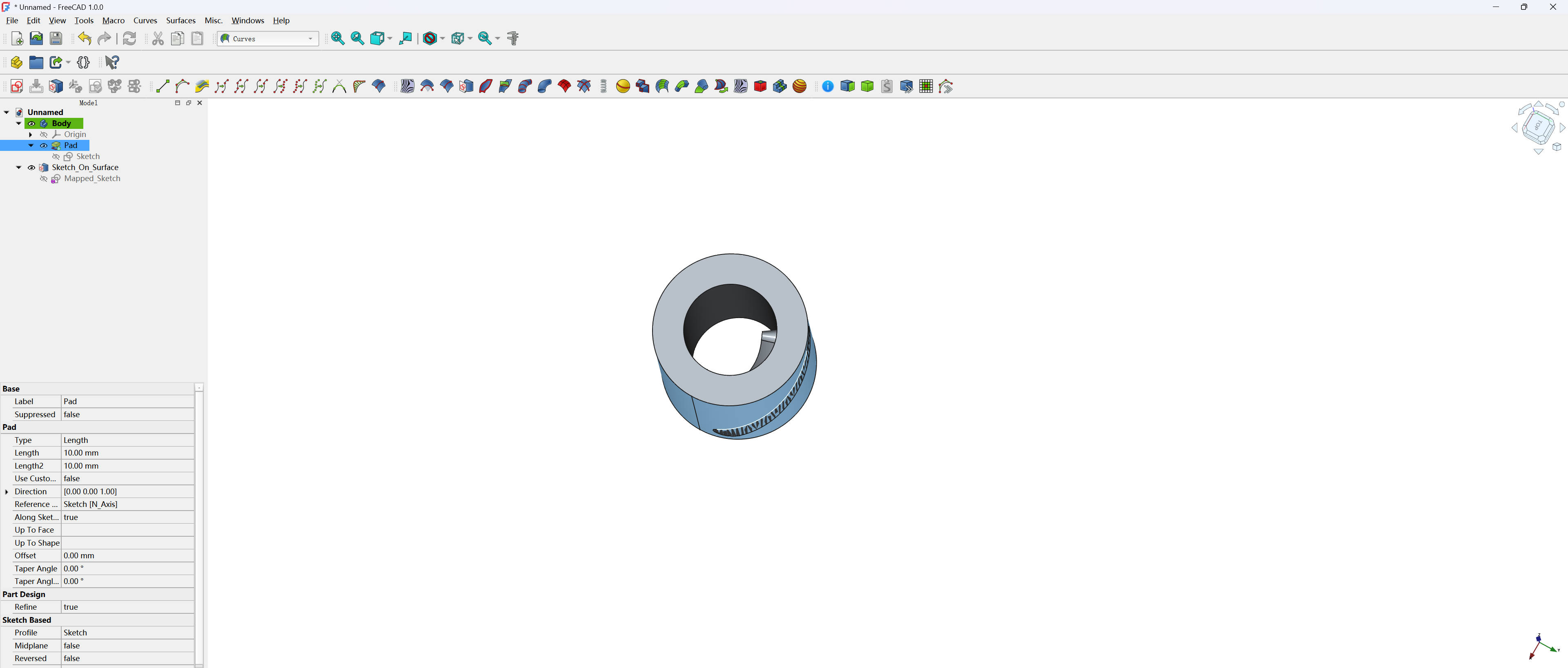
The padded slot that cuts through the cylinder.
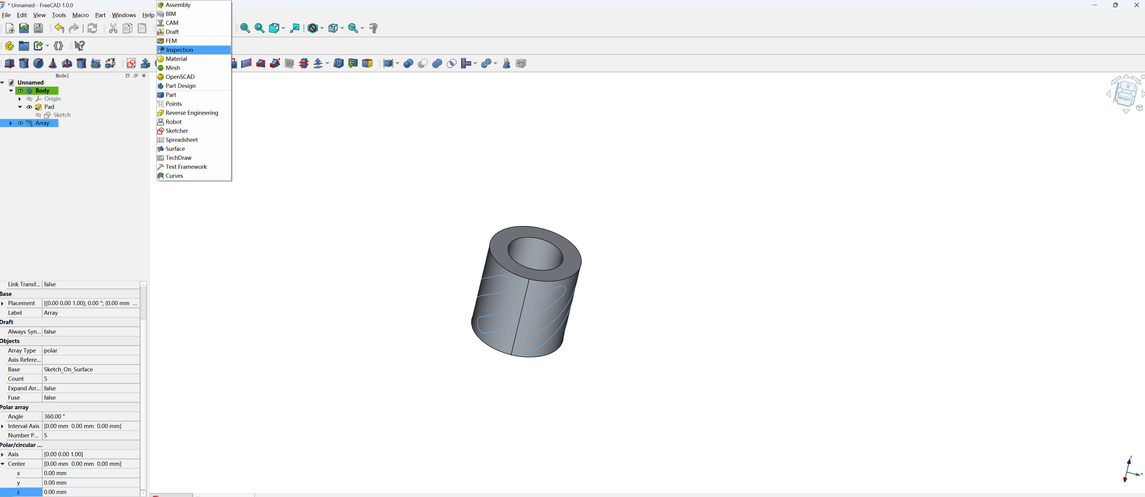
- Create a polar array
A polar array is created to replicate the slot around the cylinder at even intervals.
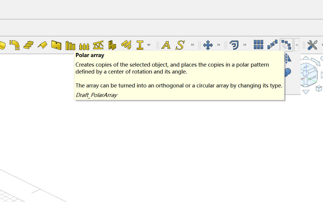
The polar array tool is used to duplicate the slot around the cylinder.
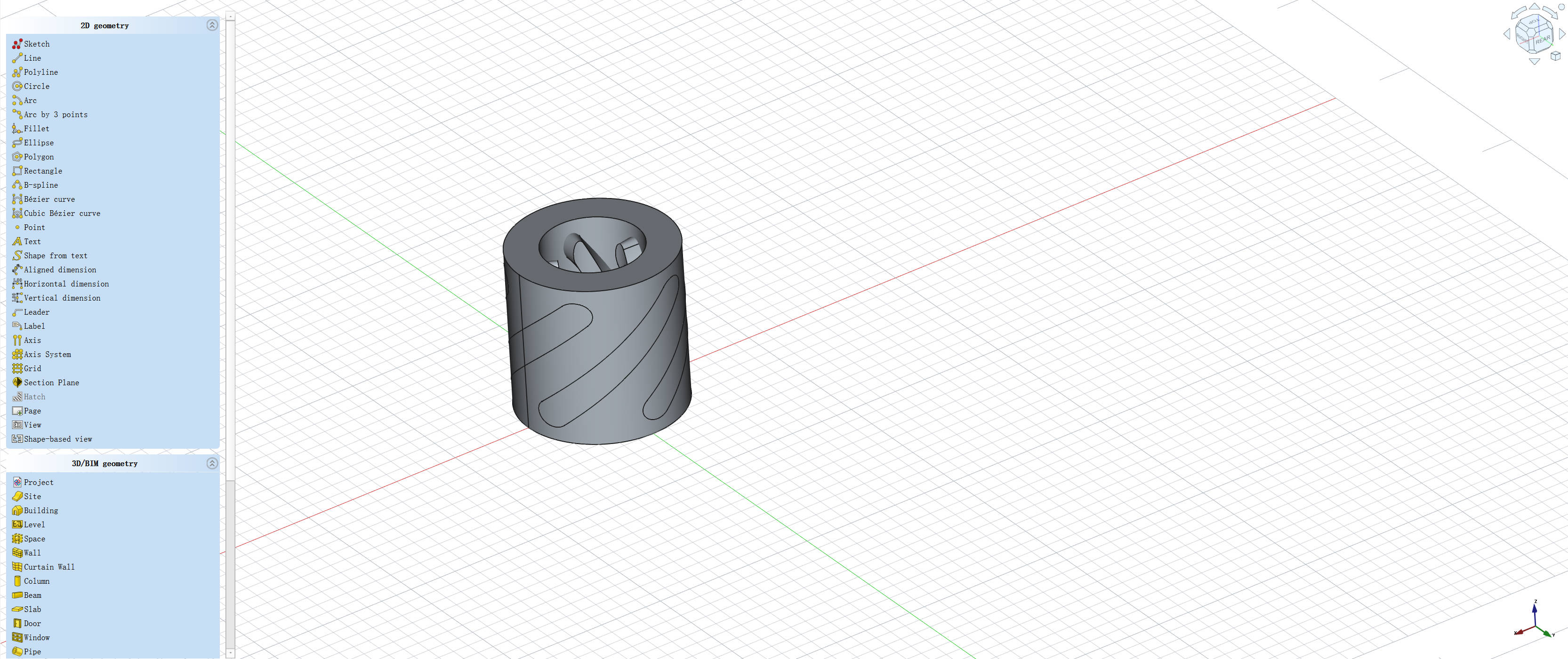
The polar array displays multiple slots distributed evenly along the cylinder.
- Perform boolean operations
Boolean operations combine or subtract the arrayed slots to form the final design of the Skeleton Cylinder.
Final boolean operation to merge the slots into the design.
Then, you can see the finished Skeleton Cylinder model, ready for export and 3D printing.
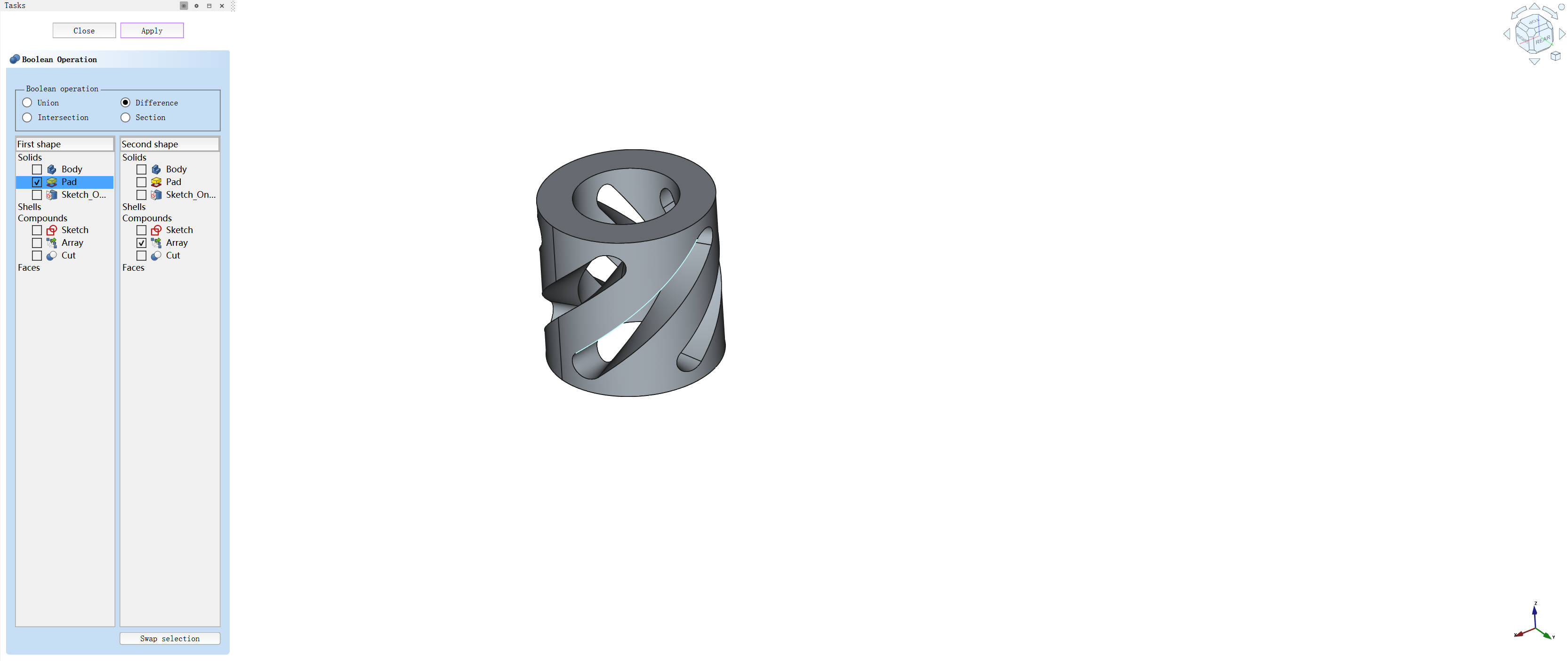
The completed Skeleton Cylinder model.
1.2 3D printing
1.2.1 Upload the model to Printer
After finalizing the model, I uploaded it to the 3D printer's slicing software to prepare for printing.
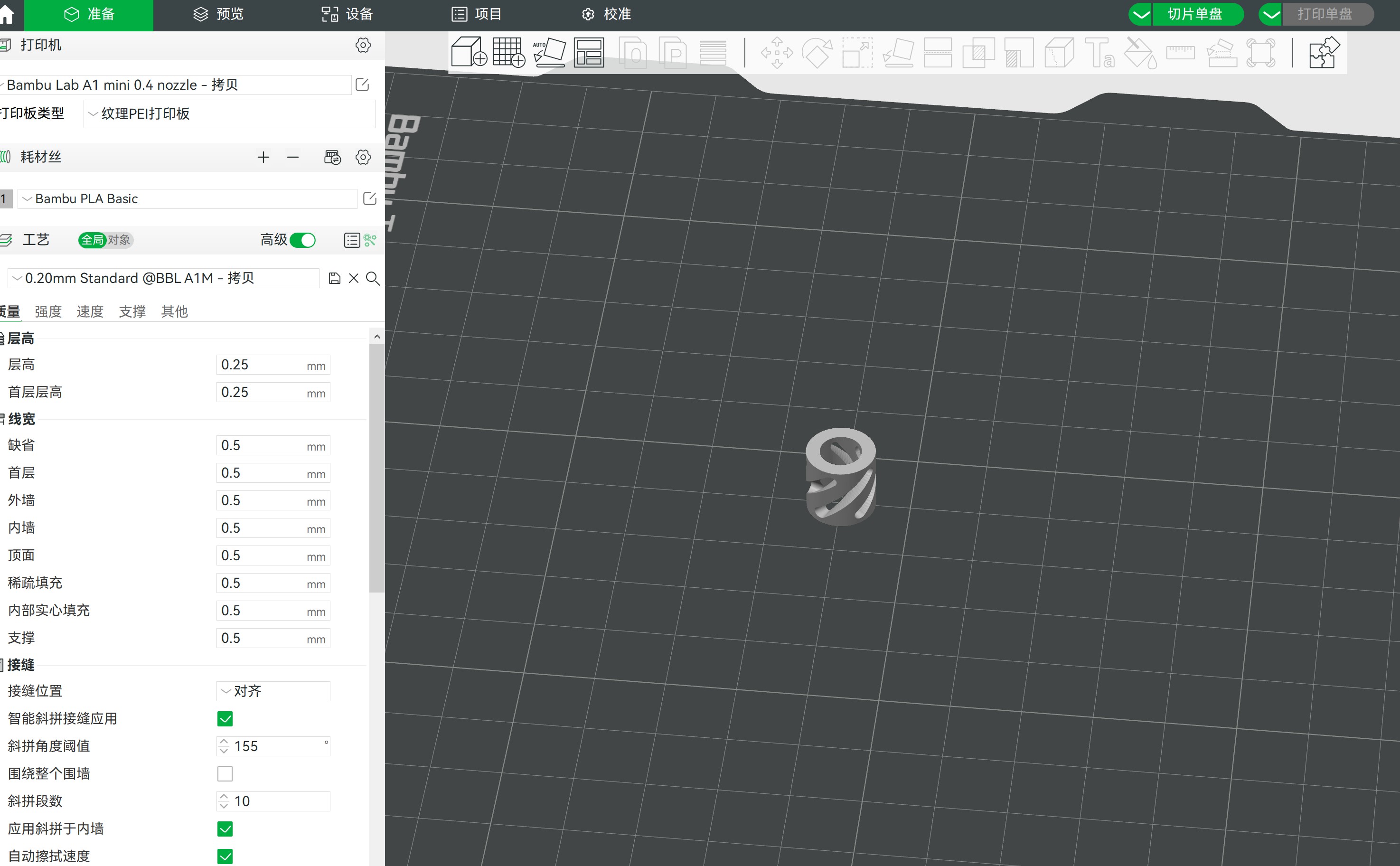
Uploading the 3D model to the printer software.
1.2.2 Slice the model
Slicing is the process where the 3D model is converted into a series of layers that the printer will print. The slicing software also generates support structures if necessary.
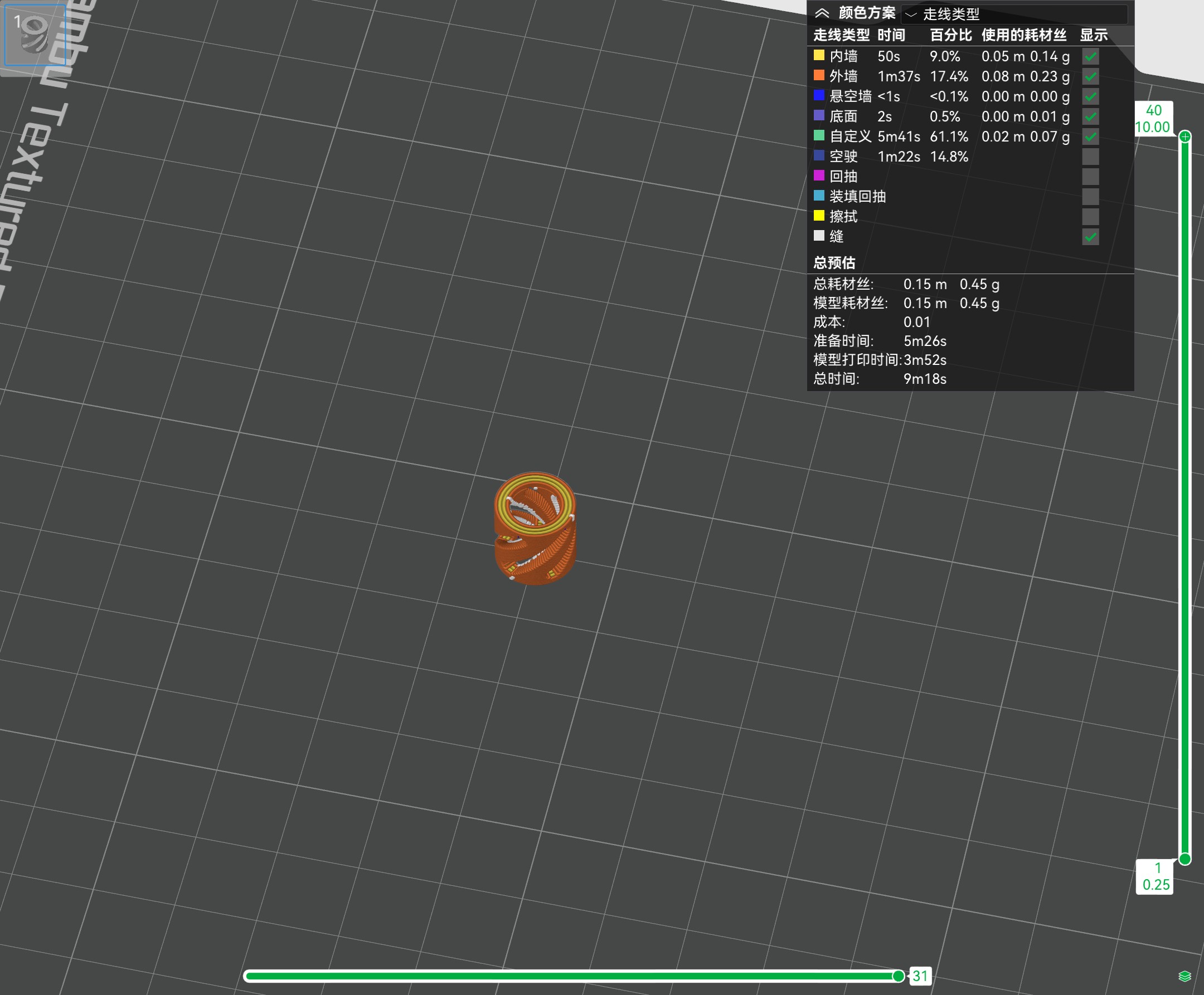
The model is being sliced to prepare for printing.
1.2.3 Print
-
Print the model
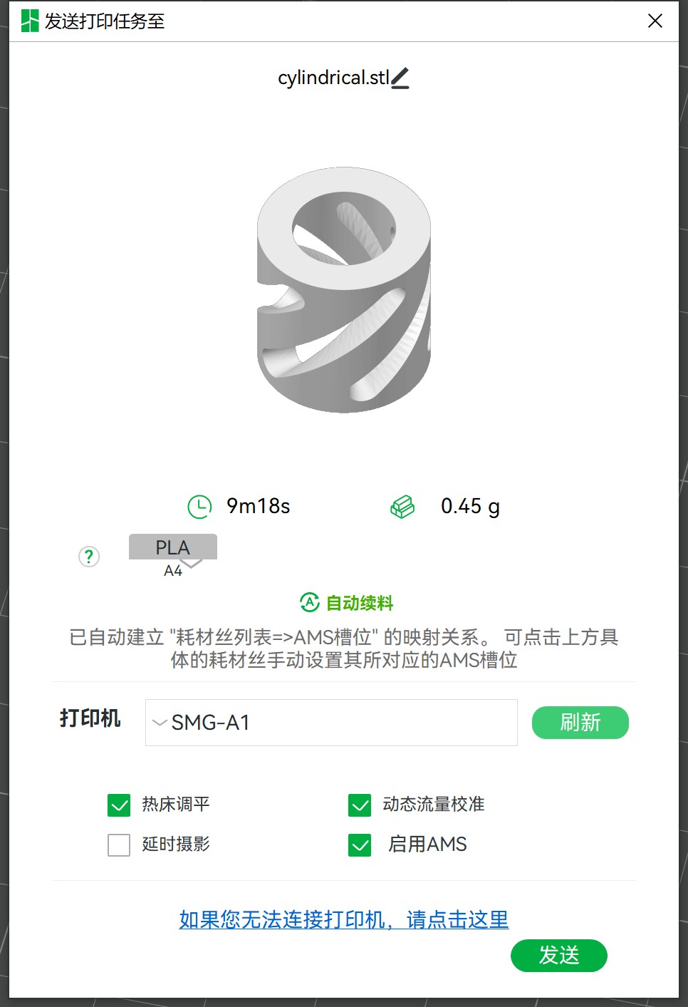
The final step is to send the sliced model to the printer and start the printing process. -
Monitor the printing progress
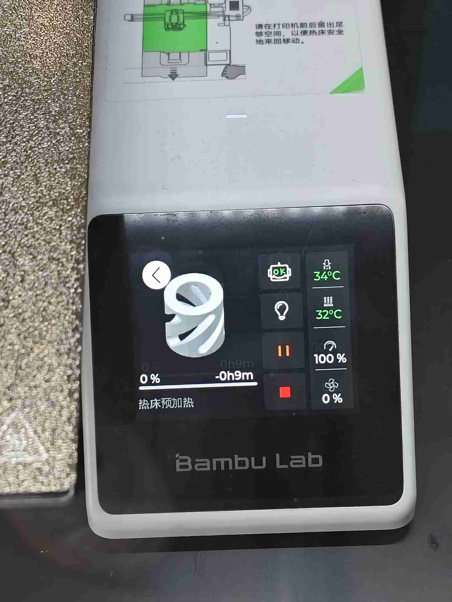
1.2.4 Final Result
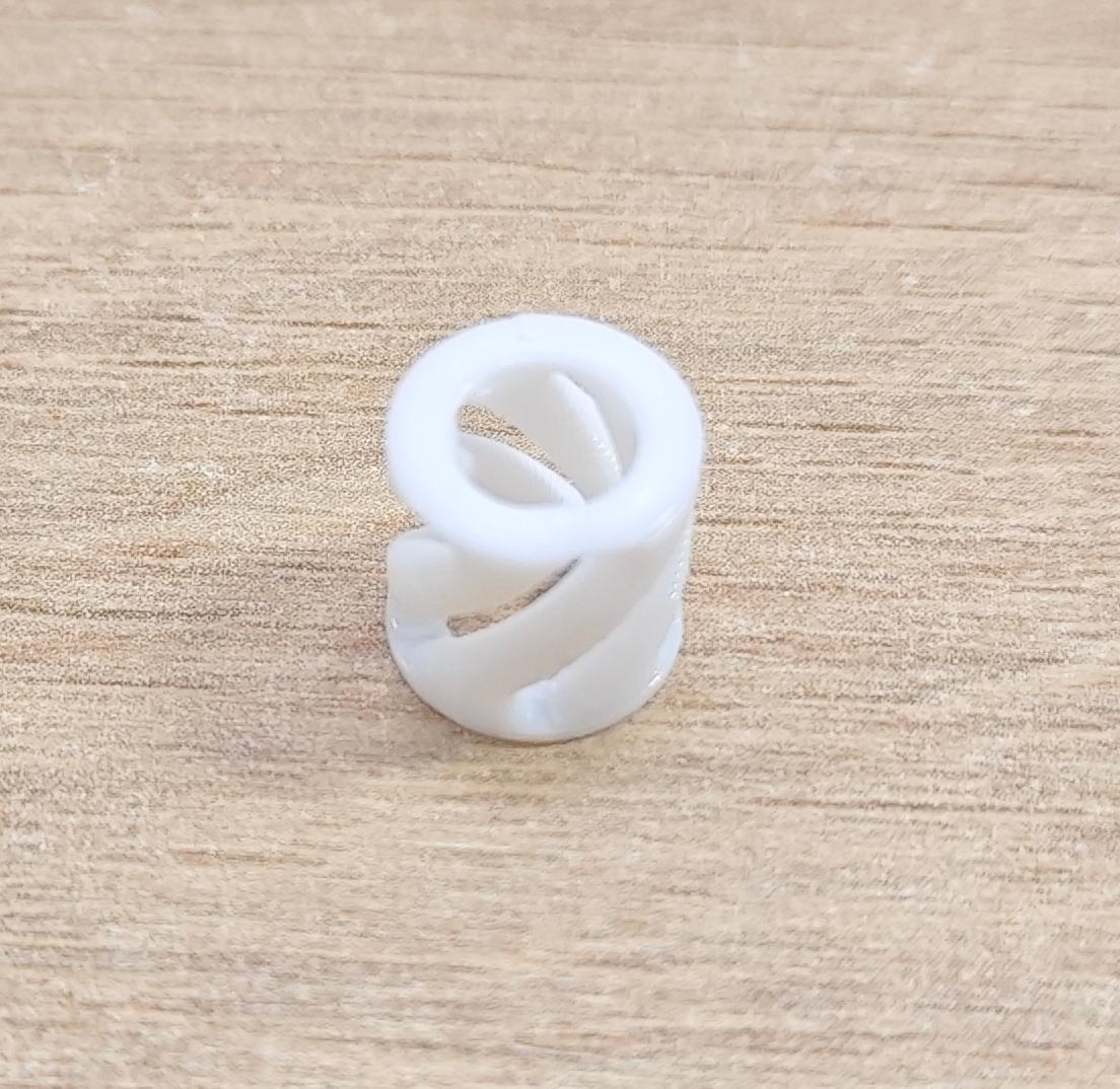 The completed Skeleton Cylinder model after printing.
1.3 Resources
- Cylinder Design File
Download the design file for the Skeleton Cylinder model in FreeCAD format. - Cylinder STL File
Download the 3D model in STL format for printing.