

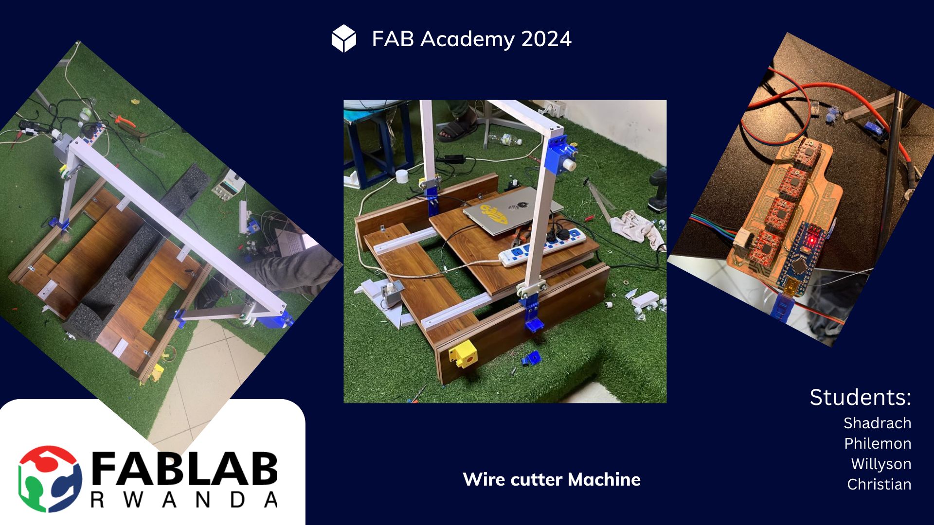
As part of our Fab Academy journey, our team undertook the task of building a machine from scratch. This collaborative effort involved several stages, including planning, designing, prototyping, and assembling various components to create a functional machine. Here is an in-depth overview of the steps we took throughout this process.
The first stage of our machine-building process involved brainstorming and conceptualizing the machine's purpose and functionality. We held several team meetings to discuss various ideas and decide on the final concept. Our primary objective was to create a machine that could automate a specific task, and we settled on building a Cutter machine for everything.
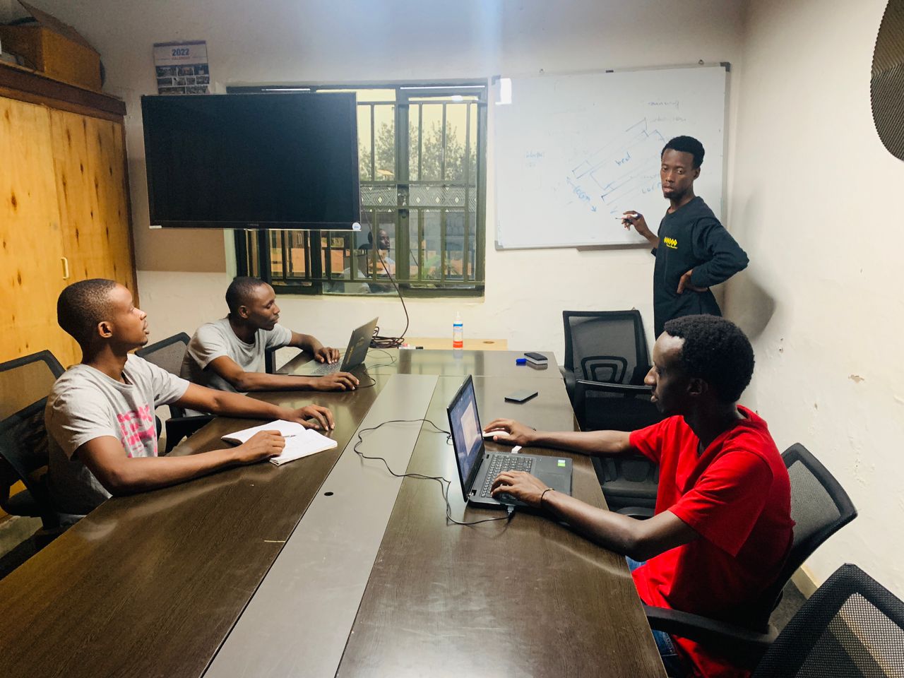
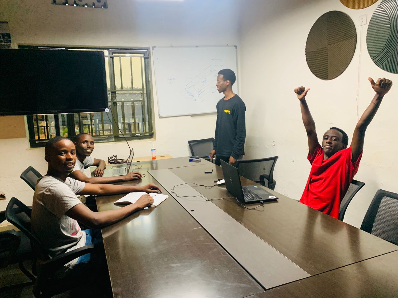
With a clear concept in mind, we moved on to designing the machine components. We used CorelDRAW software for 2D design and SolidWorks for 3D modeling. The design phase included:
* Creating detailed sketches of each part.
* Developing 3D models to visualize the assembly.
* Ensuring all parts fit together precisely.
We used CorelDRAW to design the 2D layout of the cutter's parts. This included the base, arms, and other structural components. The designs were then exported in formats suitable for laser cutting.
Using SolidWorks, we created 3D models of the machine parts. This step was crucial for visualizing how the components would interact and ensuring there were no design flaws.
Once the designs were finalized, we began the prototyping and fabrication process. This involved:
We used a laser cutter to cut the 2D designed parts from various materials such as acrylic and plywood. The laser cutter machine employed a subtractive process, precisely cutting the material to the desired shapes.
For more complex parts, we used FDM (Fused Deposition Modeling) 3D printers to create prototypes. These parts were then tested for fit and functionality.
Some parts required milling, which we performed using CNC milling machines. This ensured high precision and durability of the components.
This phase involved:
We used PCB design software to create custom circuit boards for the machine’s control system. here it is EasyEDA online software
After printing the PCBs, we soldered components such as microcontrollers (such as Arduino nano), driver motors ( such as A4988), and actuators( such as Nema17).
We programmed the microcontrollers to control the machine’s movements and operations. We used GRBL Firmware and OpenBuildsCONTROL-Setup-1 to controll the motors
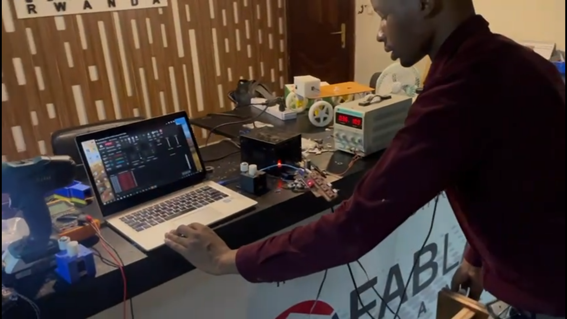
With all the parts fabricated and electronics prepared, we moved on to assembling the machine. This step involved:
Combining the laser-cut and 3D-printed parts to form the machine’s structure.
Connecting the electronic components and ensuring all wiring was secure and organized.
Conducting thorough testing to ensure the machine operated as intended. We tested the data transmission, motor movements, and overall functionality.
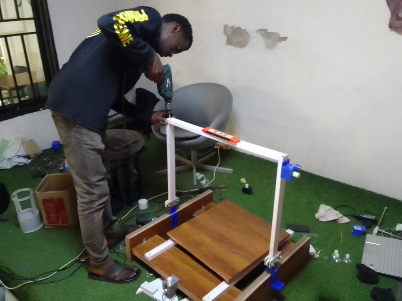
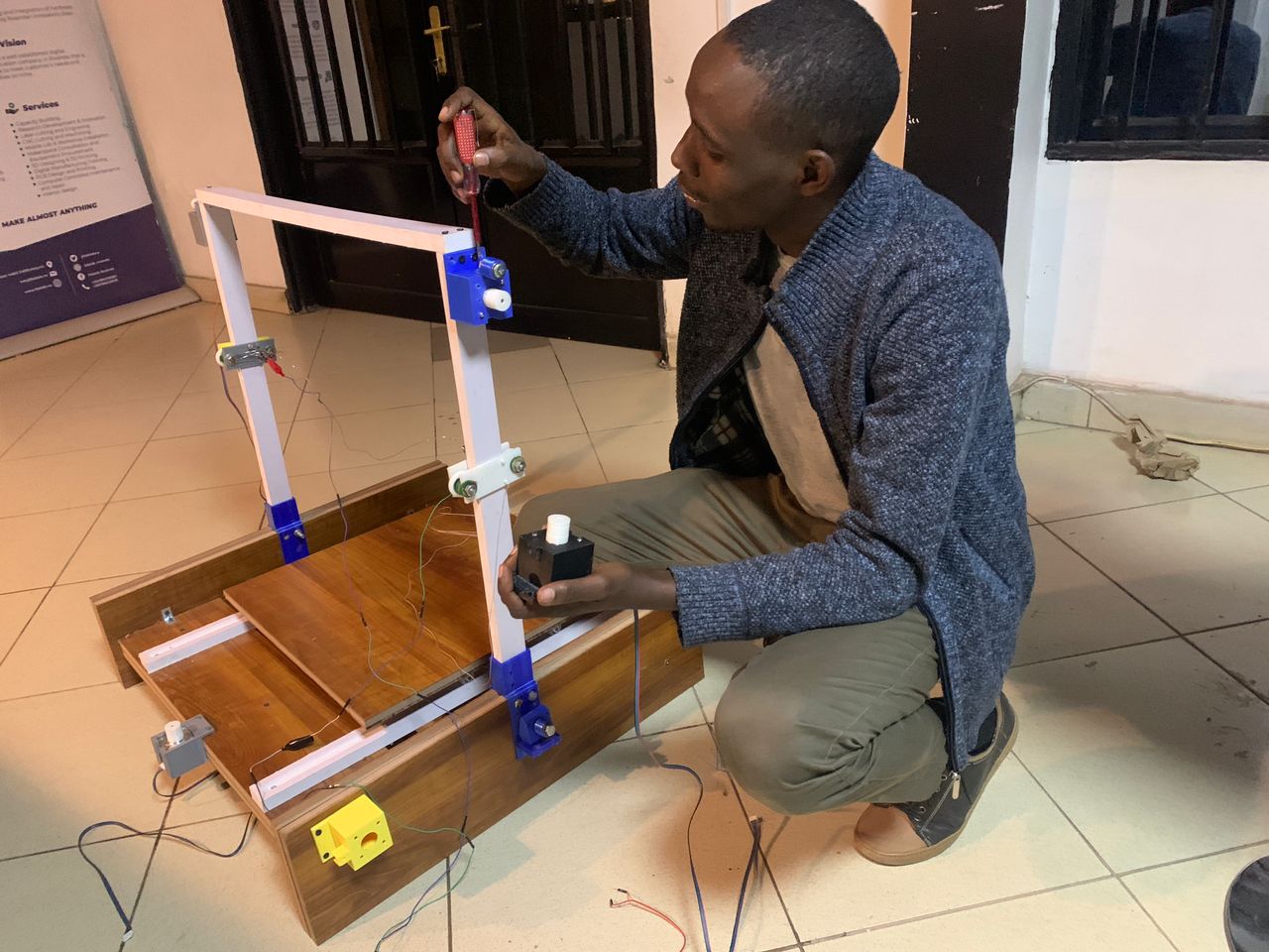
After initial testing, we made necessary adjustments to improve performance and resolve any issues. The final steps included:
Adjusting the machine's settings and configurations for optimal performance.
Documenting the entire process, including design files, schematics, code, and assembly instructions. This was crucial for future reference and for sharing our work with the Fab Academy community.
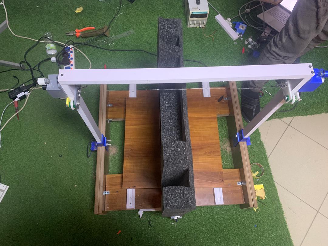
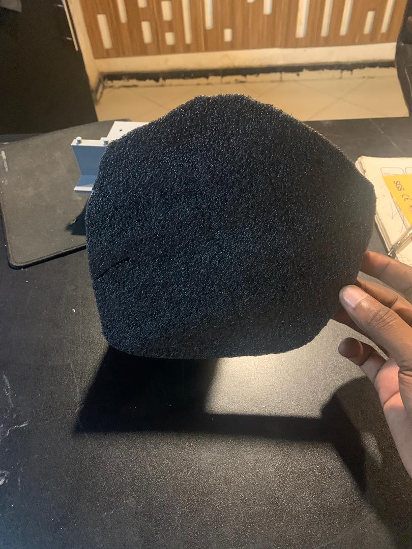
After completing each task, we aimed to cut the letter "O" as depicted in the design. This is the final result we achieved.
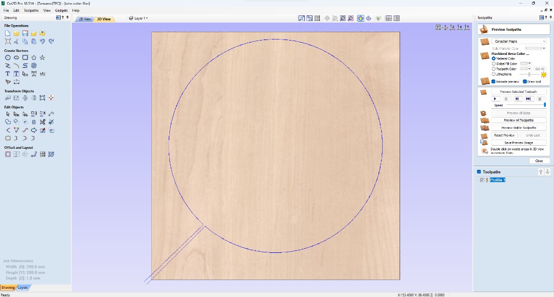
Getting Ururmbu Axis to work on our machine, both on the X and Y axis.
We found out that our machine parts are a havy to be driven by a thin string like the original urumbu design
Design around precision and manufacturing capabilities possible within our Fab Lab. On the current iteration, the hot-wire mount doesn't interact very well with the Y-axis due to loose attachments