When using the Roland SRM-20 for PCB milling, it is important to adhere to specific design rules and parameters to ensure precision and quality. Here are detailed guidelines for feeds, speeds, plunge rate, depth of cut, and tooling:
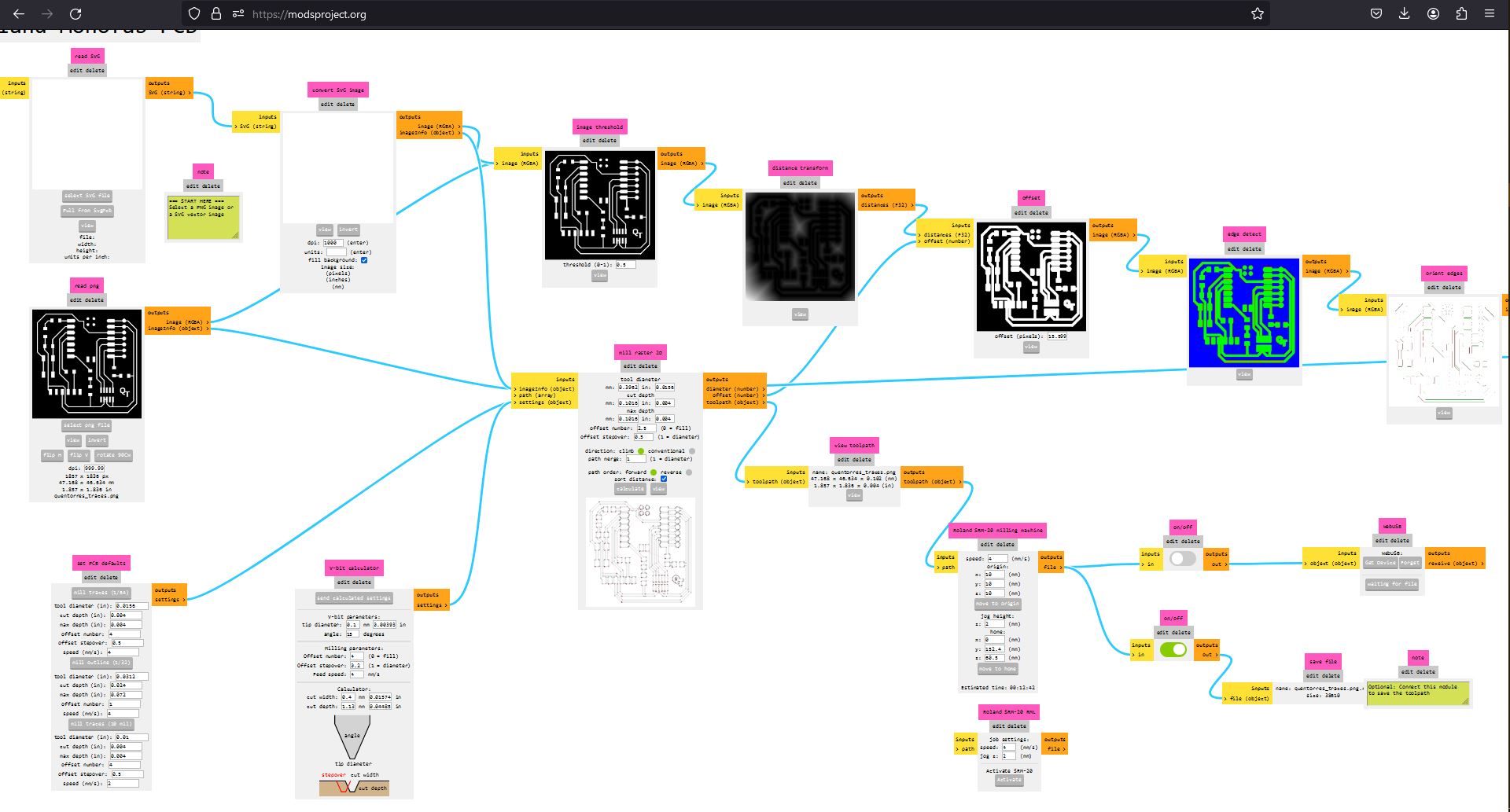
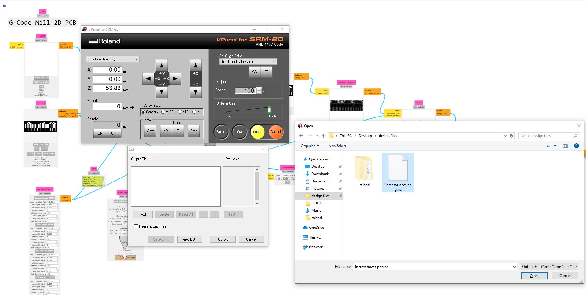
for sending the pcb to the board house, for the most part first we start with design files from CAD software whether it be KICAD or EAGLE in SVG or PNG format with that we used the mods website to generate files readable by the PCB software controller so you can do this by opening the web and right clicking the dots in the top left corner then program- open program - selected the machine which is the SRM 20 Roland - mill 2D PCB program in mods. you opened where i had to load the picture for traces (SVG & PNG), and the mill raster cell was set to:
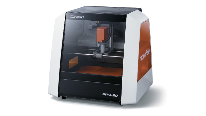
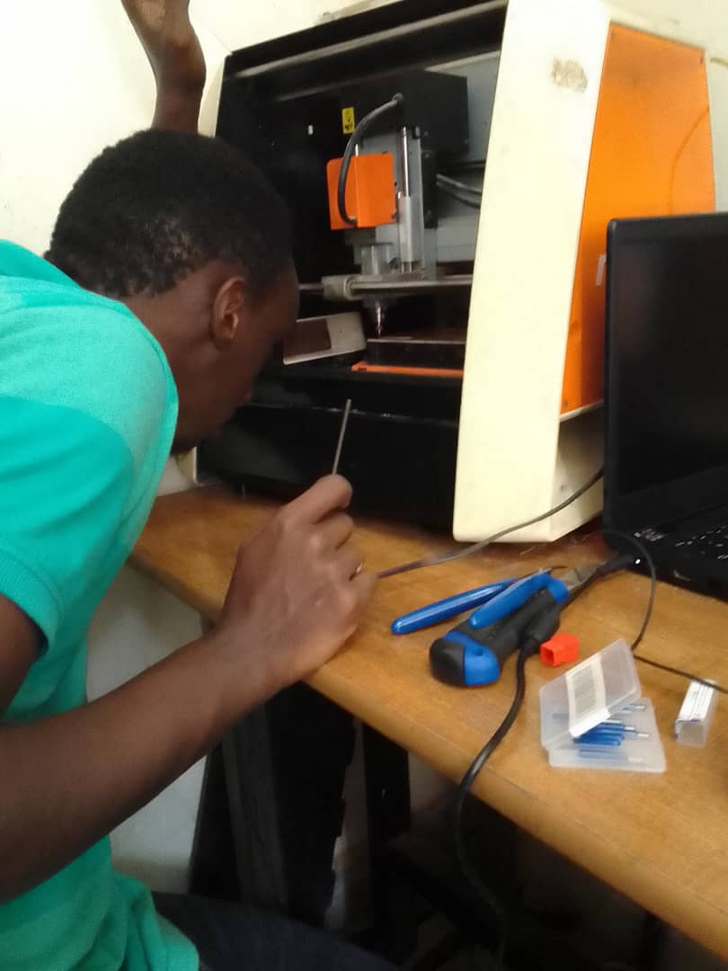
In FabLab Rwanda we have SRM-20 monofab milling machine
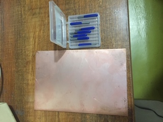
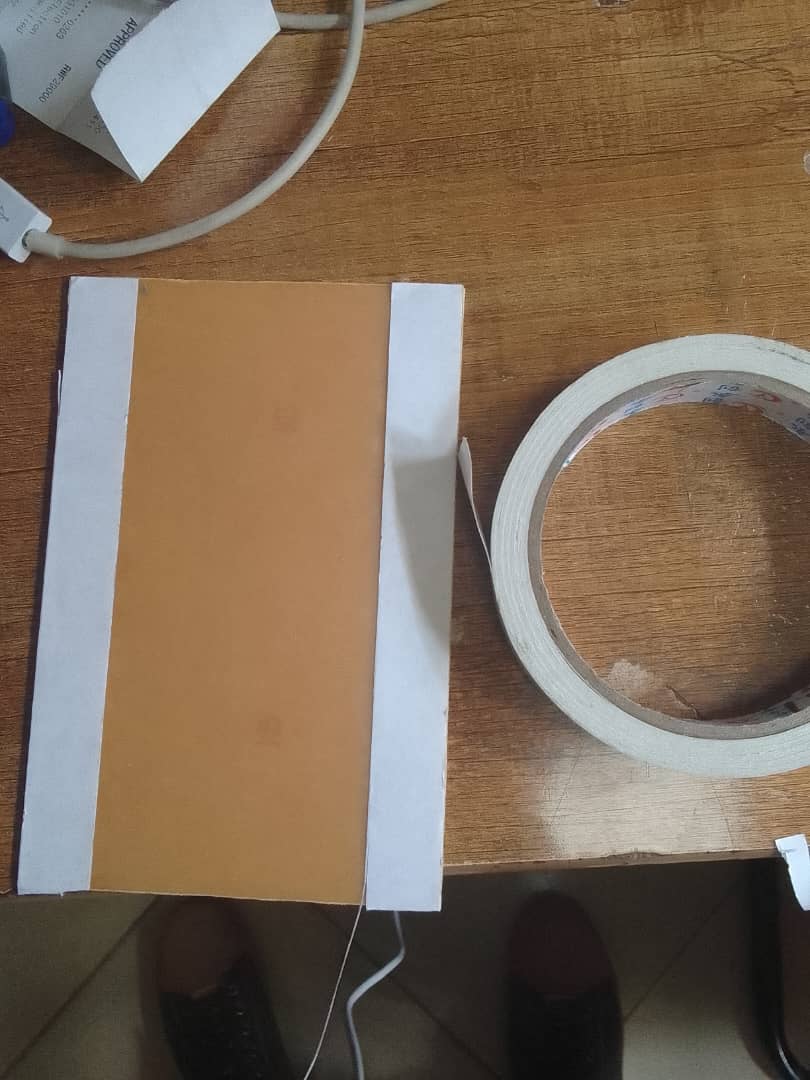
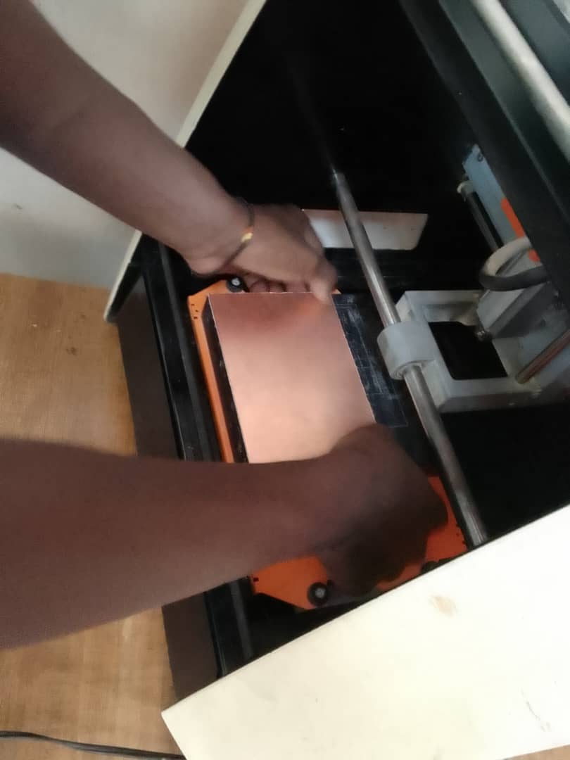
So for setting up the machine, i had the copper as the material to produce my pcb, a double sided tape to hold it on the bed of the machine and my v bits and Endmill tools to cutout the pcb. I proceeded with putting double sided tape on the copper material and laying it on the bed and then putting the tool(v bit) in the collet of the machine.
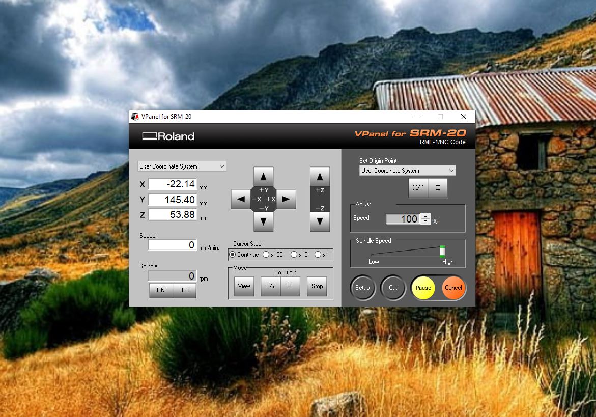
the machine has a controller, the Vpanel roland SRM-20 so we opened it to load the files generated by the modsprojects.org so we started by the testing files in order to identify and pick the the suitable traces size to use once we get to pcb design but also identify how efficient the vbit tool to be used can do traces. And so at first when you open it (first picture) the interface is simply contains coordinate system, tool movement buttons, curse step for moving fast or slow the axis, move to origin, set origin point, adjusting speed and other four buttons for set up (for machine configuration), cut(loading files), pause and cancel for stoping/cancelling the work. So when the software is opened the machine moves to the machine origin position, but its still has the origin of the last work to check this, click on XY button in the move section under TO ORIGIN and it goes to the origin of the last work done on the machine, you eliminate this by moving the axis to the point we want to be our work's origin and when we get there, go to Set Origin Point click on XY button to set xy origin point of our work, For the Z axis, after putting the tool in the collet i used the method explained in class to set the Z axis which is done by lowering the tool with the machine so that it gets nearer the pcb surface and then loosen it up by opening the collet and the tool fall on the surfaces, retighten the collet to hold the tool to that point click the Z button under Set Origin Point and then raise it up a little bit before it starts milling. To load files you click on cut it opens a window and click on deleteall to remove previous work, then click on add should directly take to the generated files, open them and then click on outpout and the machine starts right away.
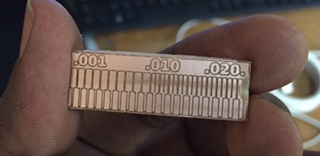
As you can see we came up with some good result but due to how small the traces are and the path of the tool the pcb got chipped on its right side as we were trying to remove the pcb from the board.