Design a machine that includes mechanism + actuation + automation + application
Build the mechanical parts and operate it manually
Document the group project
Individual assignment:
Document your individual contribution
Mechanical Design and Machine Design Week
During the week of Mechanical Design and Machine Design, our group was tasked with developing a machine that can cut foam using a nichrome wire. You can find the detailed group assignment here.
My Contribution
As part of the group, I was assigned the responsibility of designing the electronic part of the machine. Below is a detailed documentation of my tasks:
Task Overview
Designing the Electronic Board
Selecting Materials
Using EasyEDA for PCB Design
Fabricating the PCB
Assembling and Soldering the Components
Using OpenBuilds CONTROL software
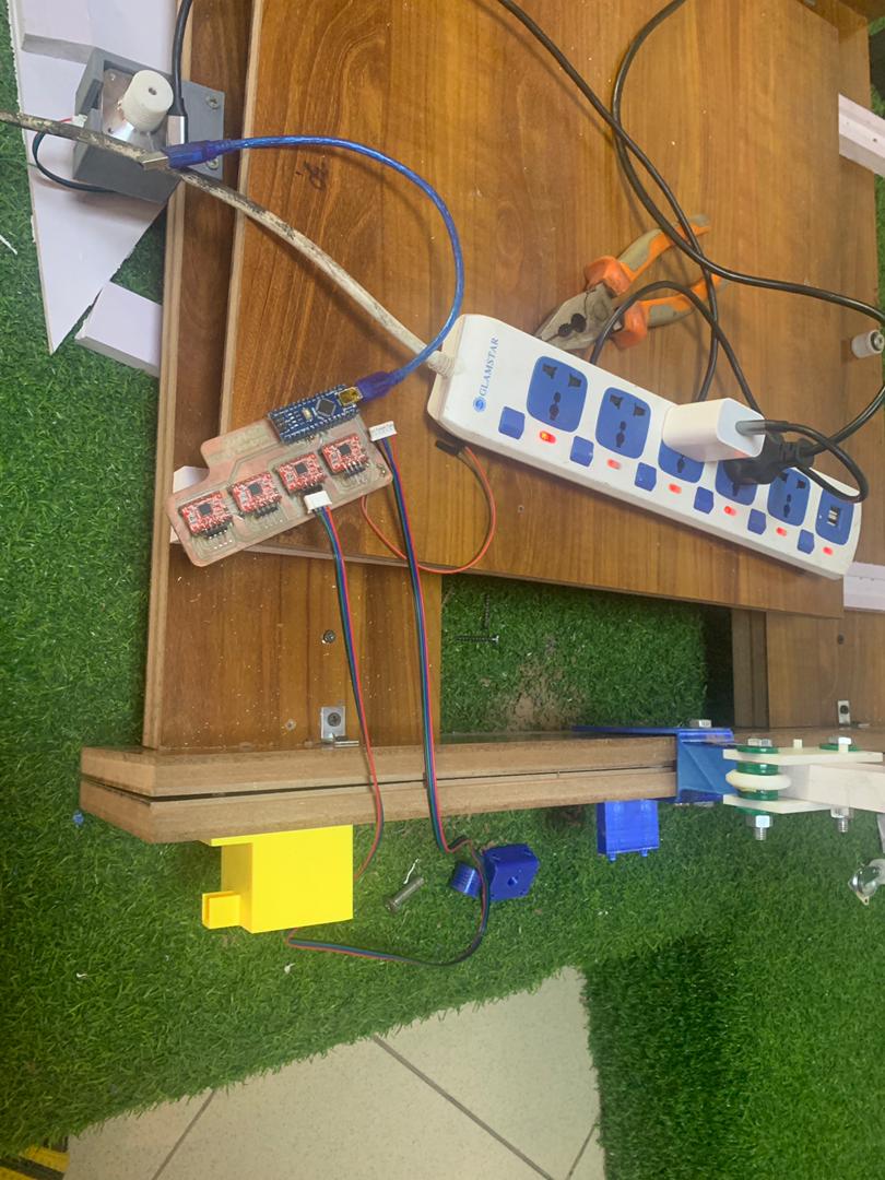
Mounting on Machine
Designing the Electronic Board
The primary goal was to create an electronic board capable of controlling the mechanical parts of the foam-cutting machine. The board needed to interface with the nichrome wire cutter and the motors that move the wire.
Selecting Materials
To control the various components of the machine, I selected the following materials:
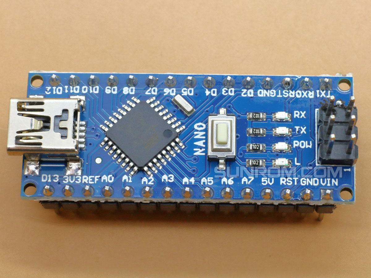
Arduino Nano: Chosen for its compact size and versatility.
Power Supply Pins: To accommodate the different voltage requirements (12V and 5V) of the machine.
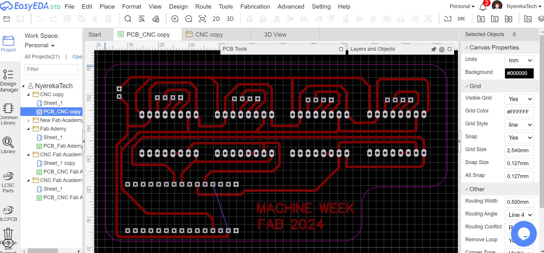
Using EasyEDA for PCB Design
I used EasyEDA for designing the PCB as I am familiar with this online software. Here are the steps I followed:
Schematic Design:
I began by creating a schematic of the electronic circuit, ensuring that all components were correctly placed and connected.
PCB Layout:
After finalizing the schematic, I designed the PCB layout, optimizing it for minimal size and efficient routing.
Review and Confirmation: Once the design was complete, I reviewed it with my instructor to ensure it met all requirements and made necessary adjustments based on the feedback.
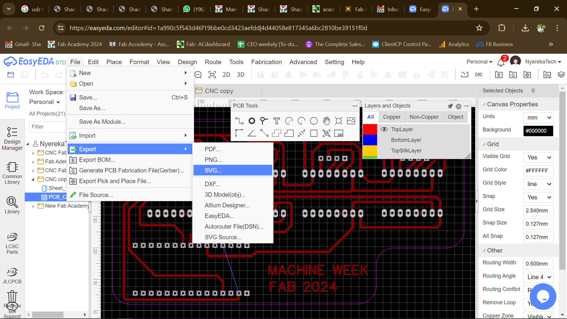
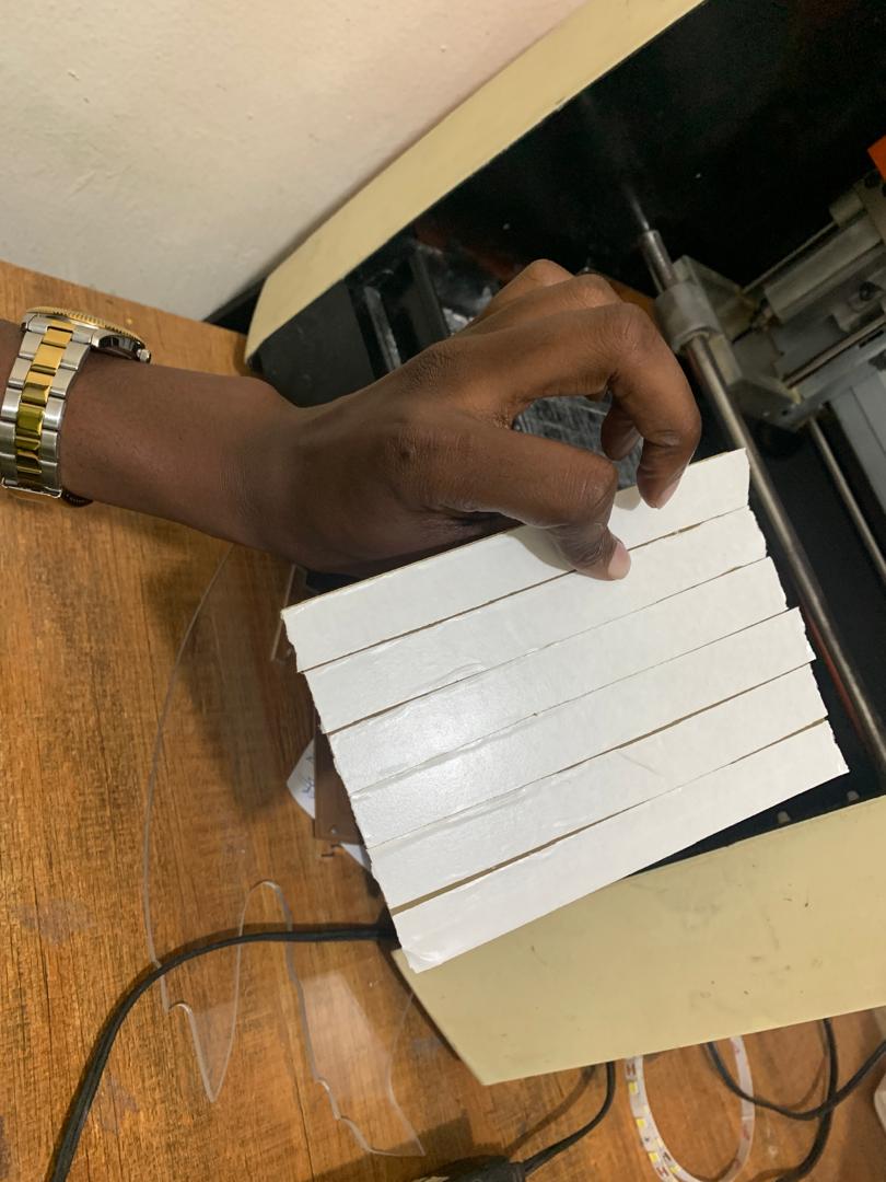
Fabricating the PCB
After finalizing the design in EasyEDA, I used the Monofab PCB printer to fabricate the board. The steps involved were:
Exporting Gerber Files: I exported the Gerber files from EasyEDA, which are necessary for PCB fabrication.
Printing the PCB Using the Monofab PCB printer, I printed the board, ensuring all traces and pads were correctly transferred.
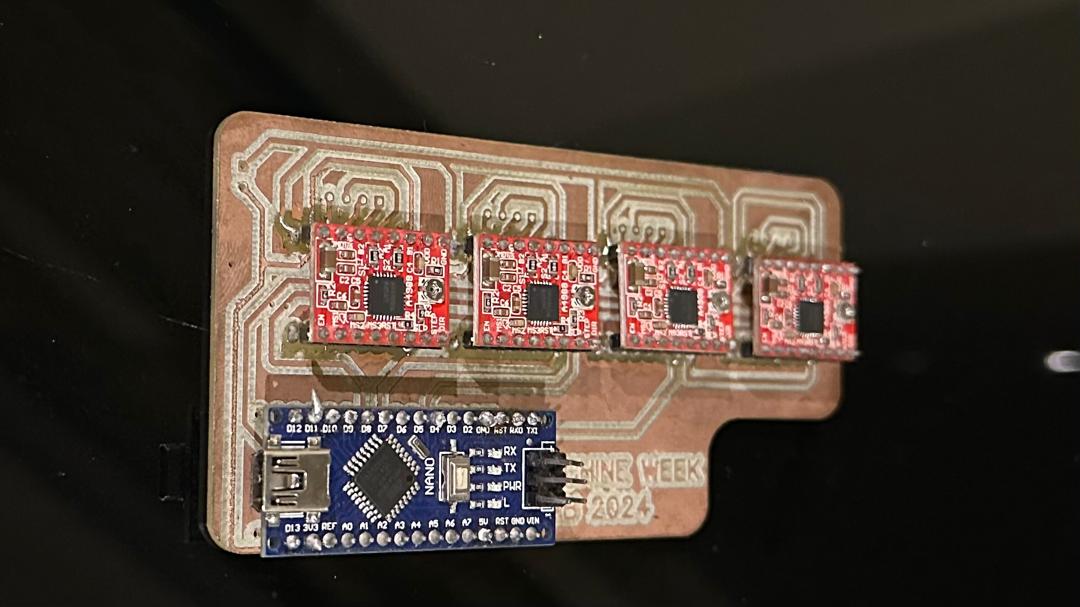
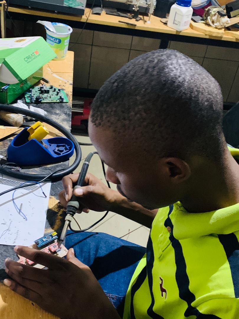
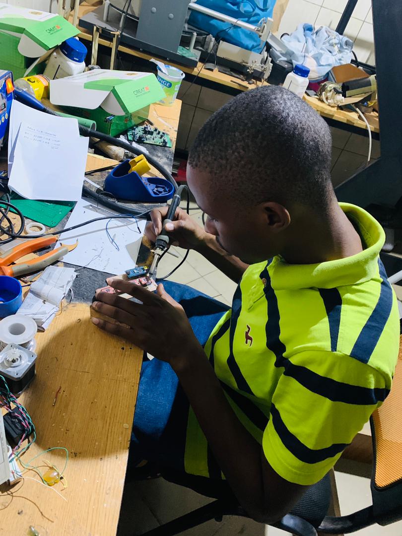
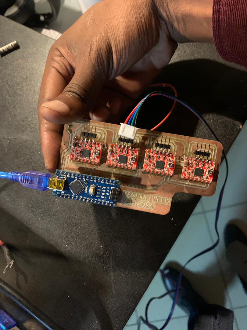
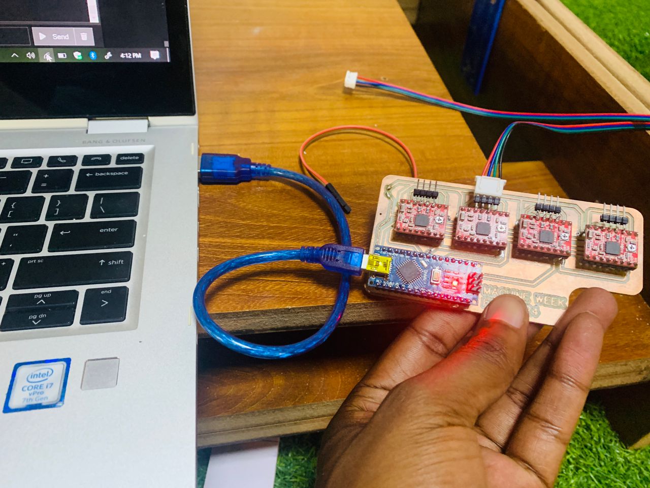
Assembling and Soldering the Components
Once the PCB was printed, I proceeded with the assembly:
I carefully placed all components (Arduino Nano, motor driver, capacitors, resistors, etc.) onto the PCB.
Using a soldering iron, I soldered each component to the board, ensuring secure and reliable connections.
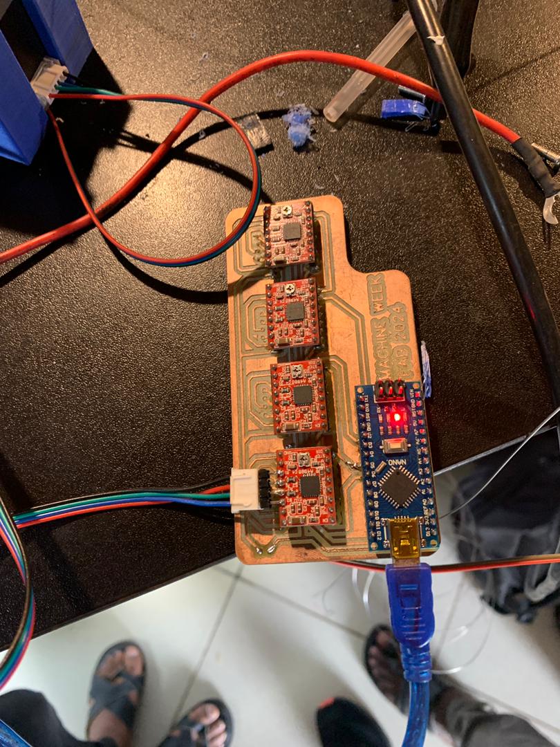
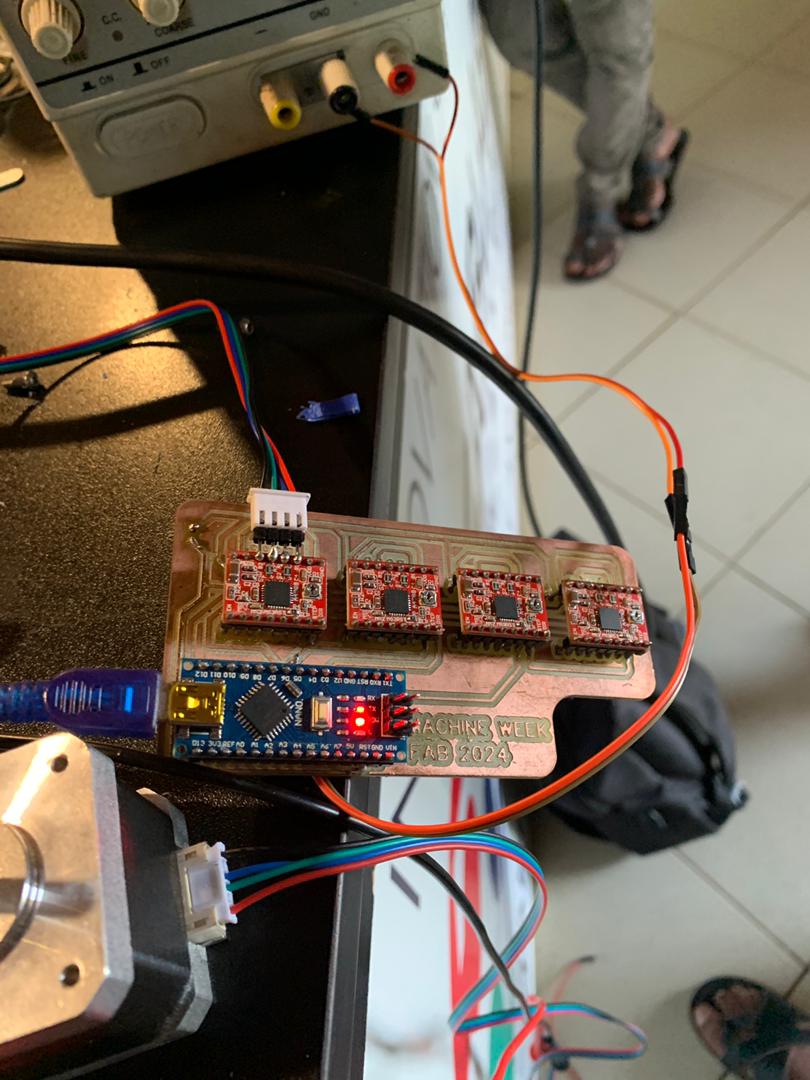
After assembly, I tested the board to ensure it functioned correctly and could control the mechanical parts of the machine as intended.
Install and Configure OpenBuilds CONTROL Software
Download and Install OpenBuilds CONTROL Software from the OpenBuilds website here
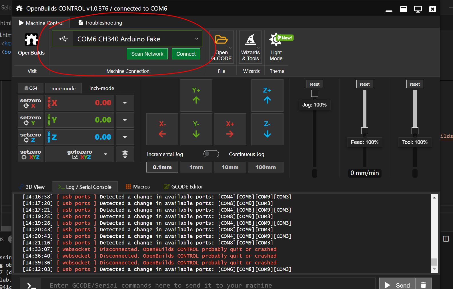
Connect Your Arduino Nano to your computer via USB
Open OpenBuilds CONTROL Software and select the correct COM port for your Arduino Nano.
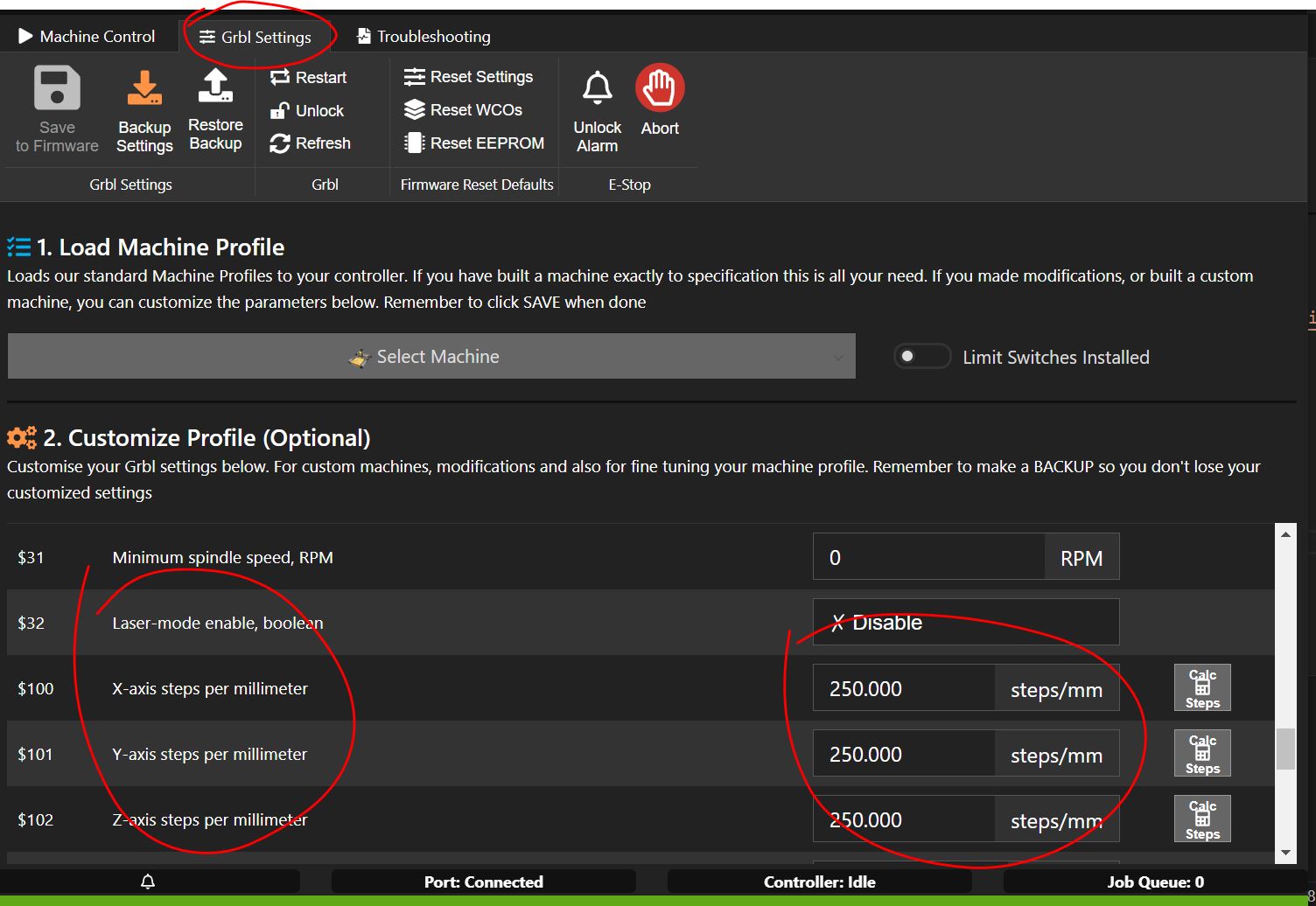
Configure and Control the Motor
Go to the machine profile settings and set up your machine parameters (e.g., steps per mm, max speed)
Use the jog controls to move the motor. You can adjust the speed and step size according to your needs.
Video for control motor Testing
Video of my work in this Group_Assignment
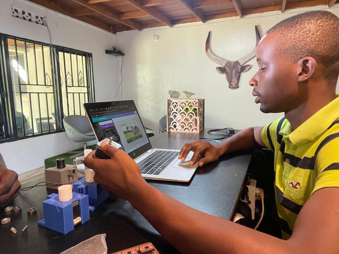
Experience Opbtained
For this group assignment on machine design, I gained the skills to connect multiple motors and used the Nema 17 motor for the first time. I also learned to use the OpenBuilds controller software to control multiple motors for a single task. I have handed over my tasks to the other team members to finish the machine this week. My work was executed perfectly, as demonstrated in the video above. You can find the fully functional machine in the group assignment.