Week 10
Mechanical Design, Machine Design.
Group Assignment.
The group assignment can be found here
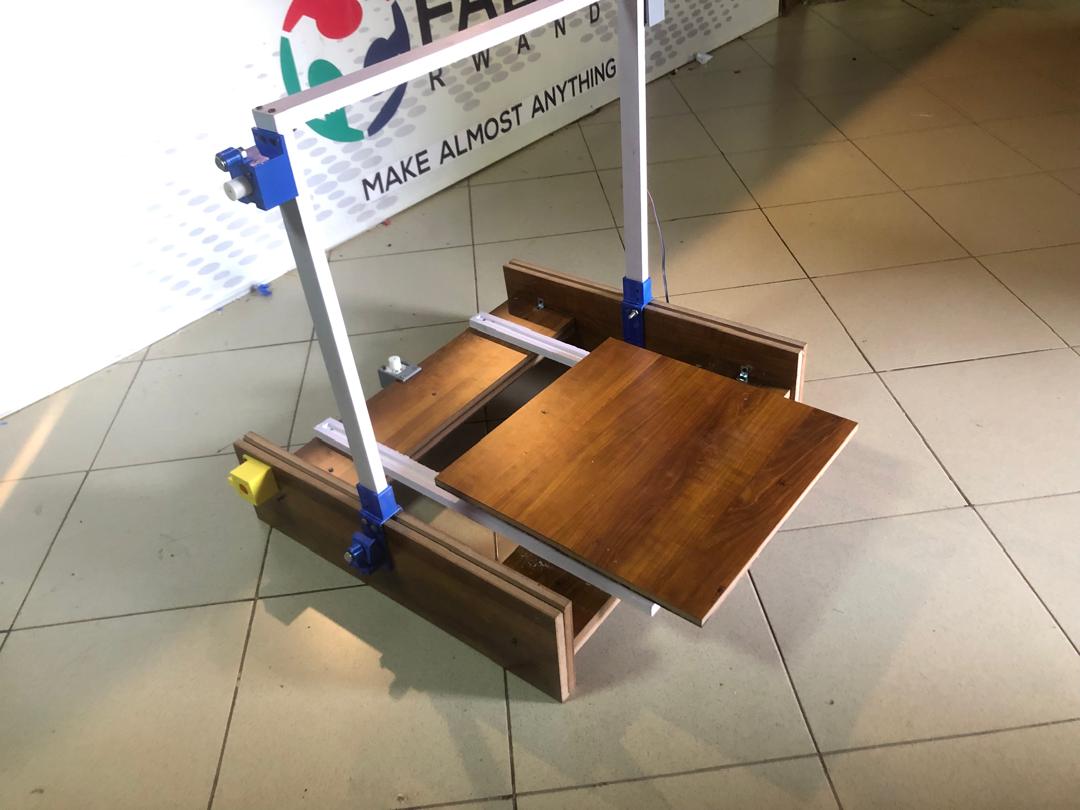
For this week's assignment i worked around the machining part on the cnc of building this machine, so after working on the design a bit on the side of design to ensure that whats being designed can also be machined on our cnc router
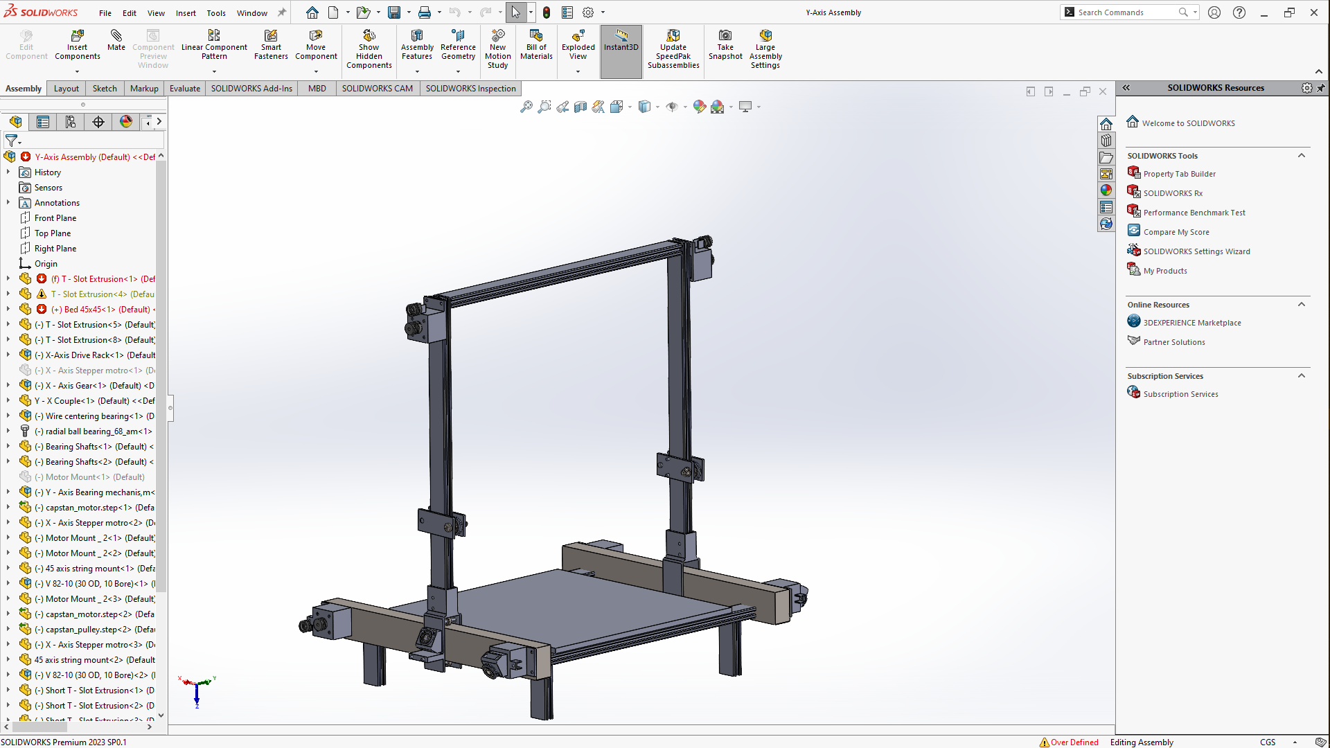
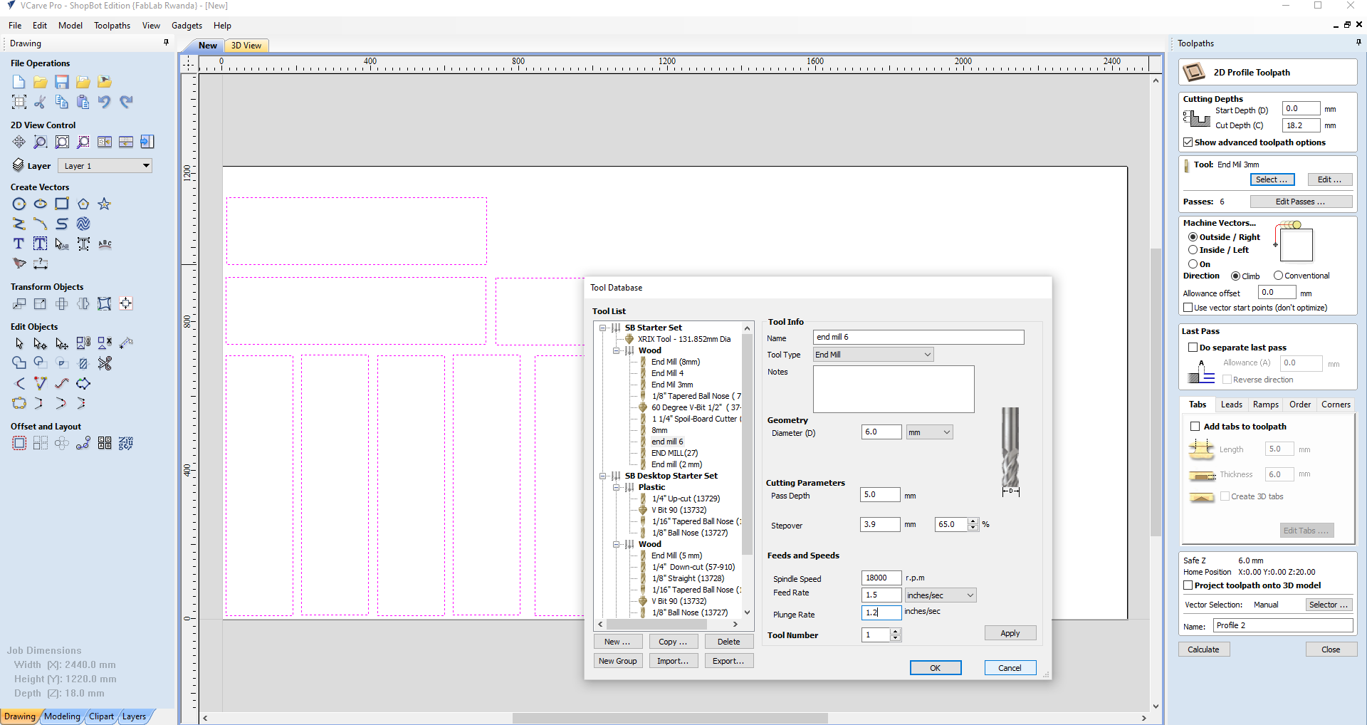
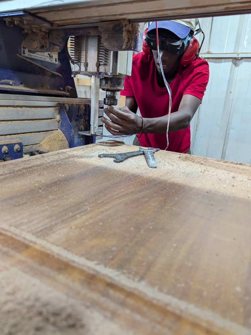
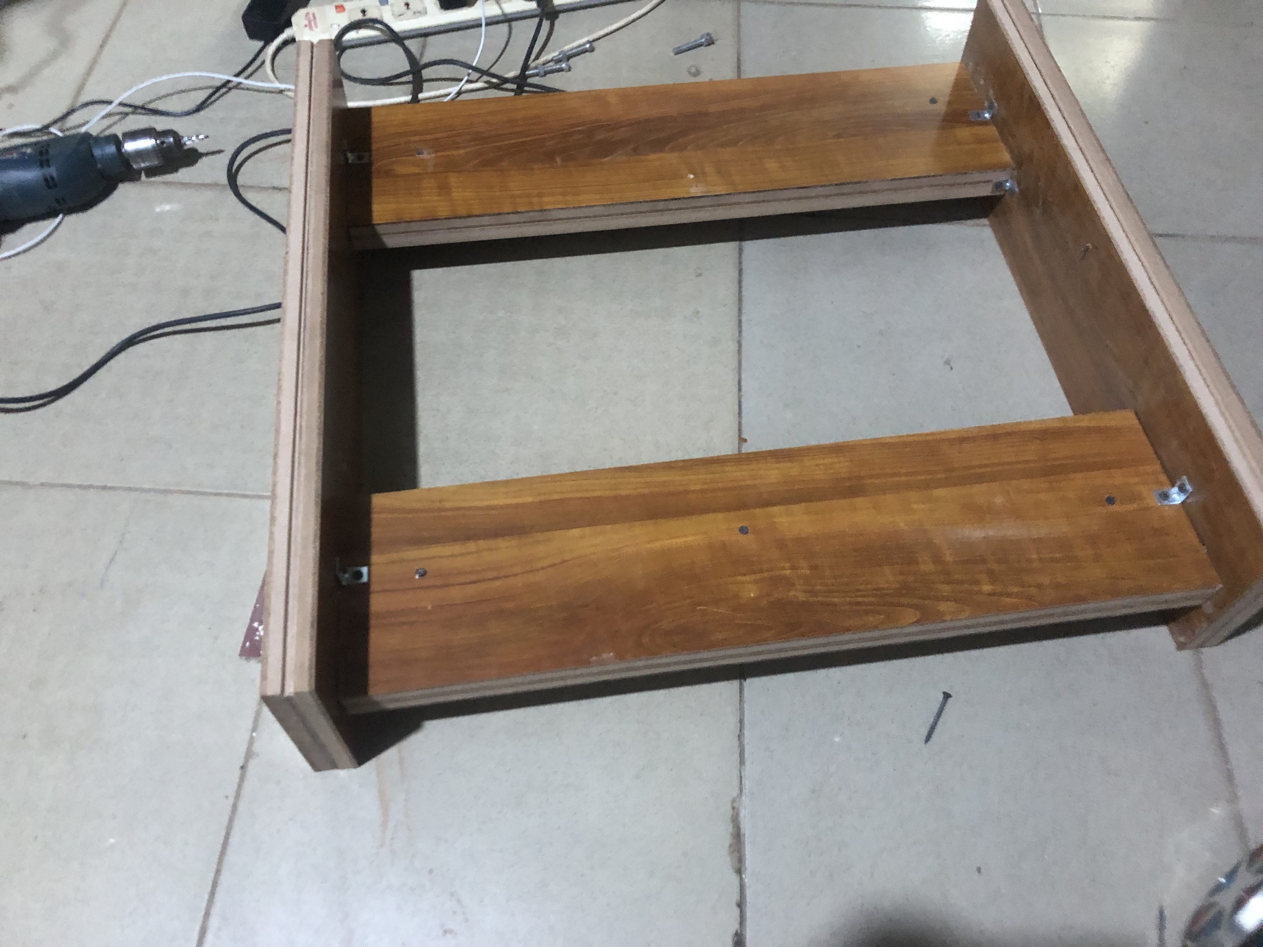
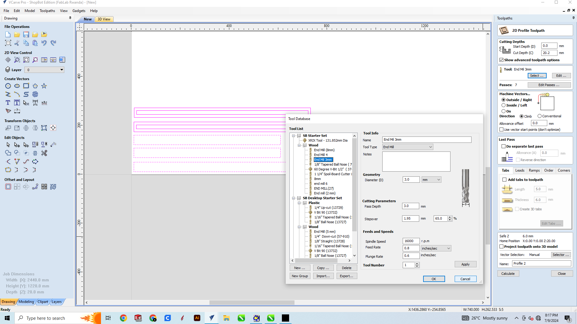
we wasn't able to get the parts which were supposed to be metals so i made modification based on the matetrials available i started by designing 4 rectangular shaped Pieces of 18cm _70CM using Vcarve, this will be the x axis and i joined them both using other 4pieces Of 18CM-80CM and square of 50X50CM which will be the bed workspace of the machine, after calculated the toolpath using the shown settings then launched the job, keeping in mind that this was done on a mdf material of 18MM thickness.
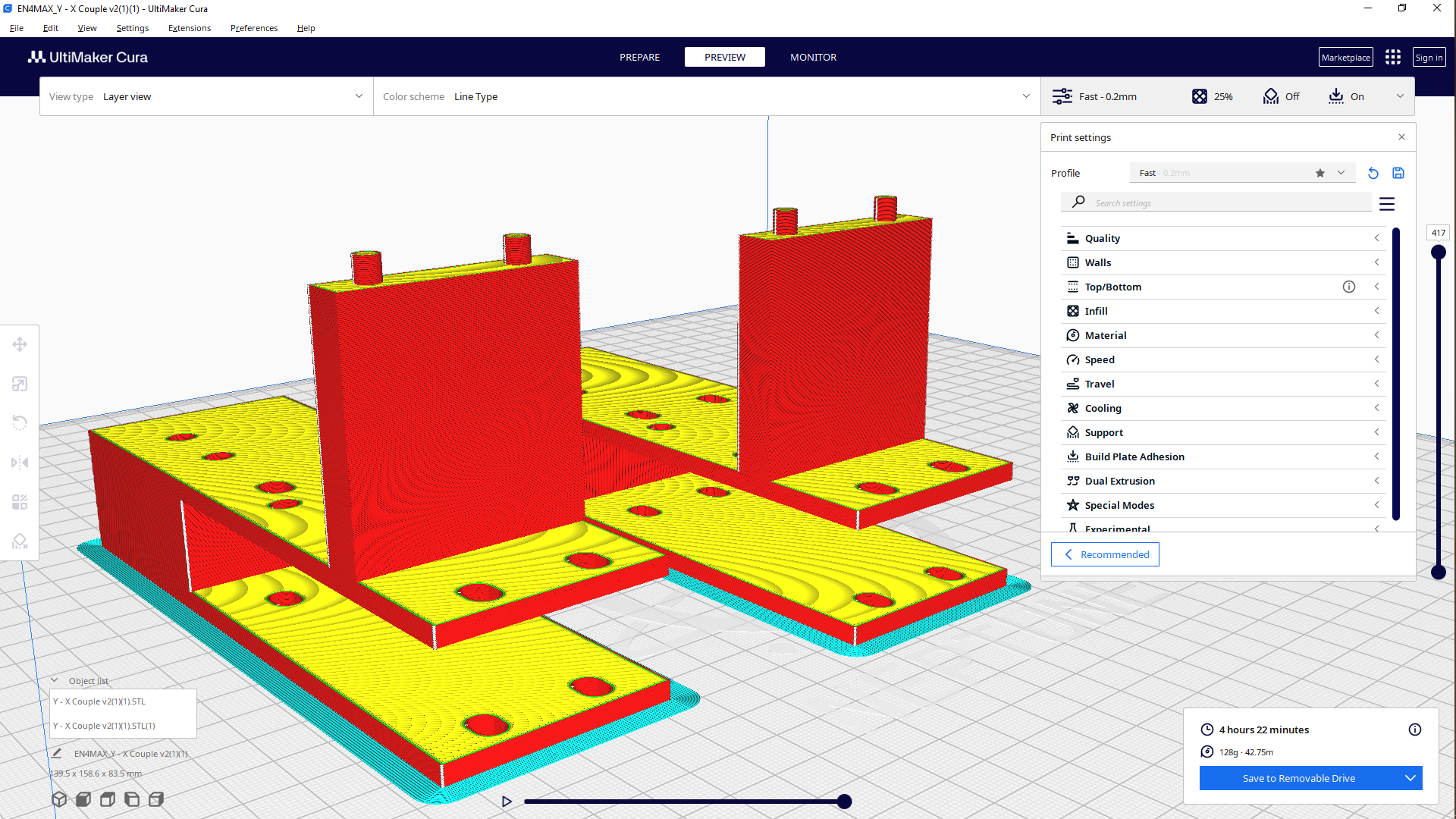
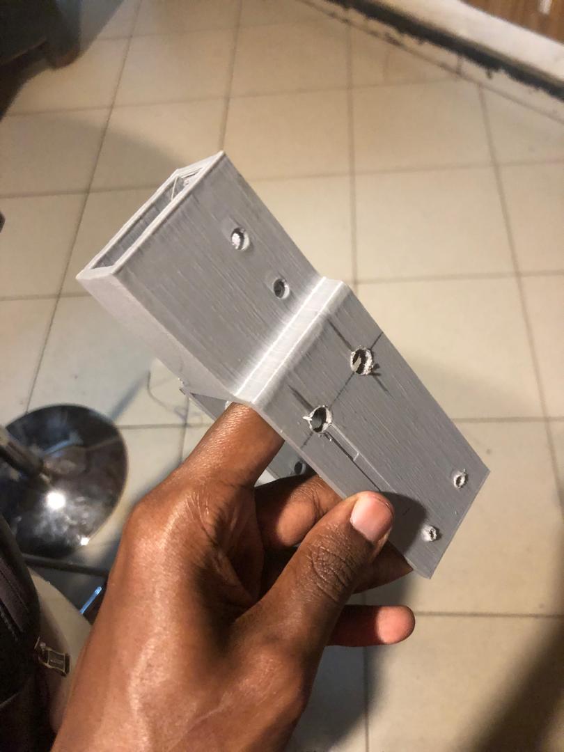
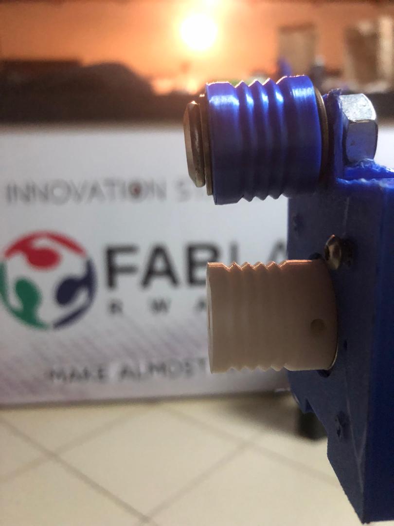
From the machine designed earlier, there was certain parts that were printed using 3D printer, so 2 pieces on which the handles of z axis will be standing on, we called this xy coupler.
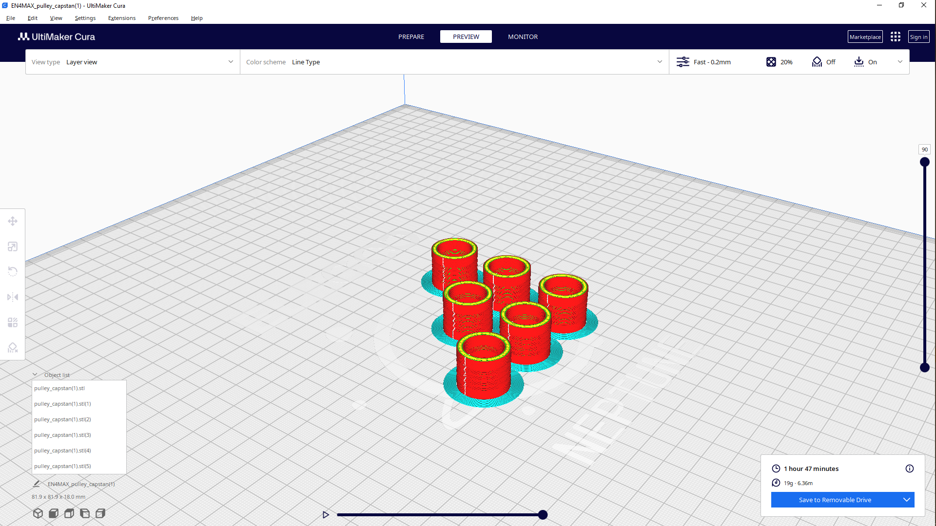
I printed these six pieces as part of the initial idea of using pulleys as a way of moving the wirecutter on z axis, after i printed the motor holder/mount to hold firmly the motor, so i printed 3 pieces also
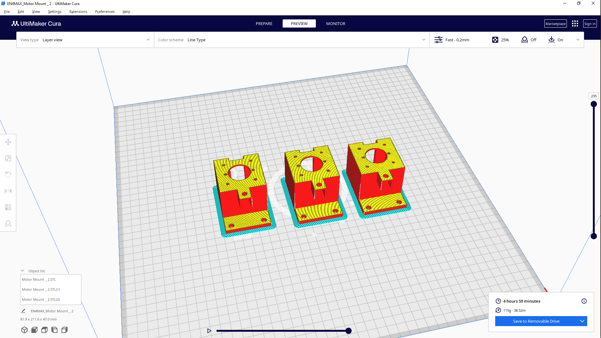
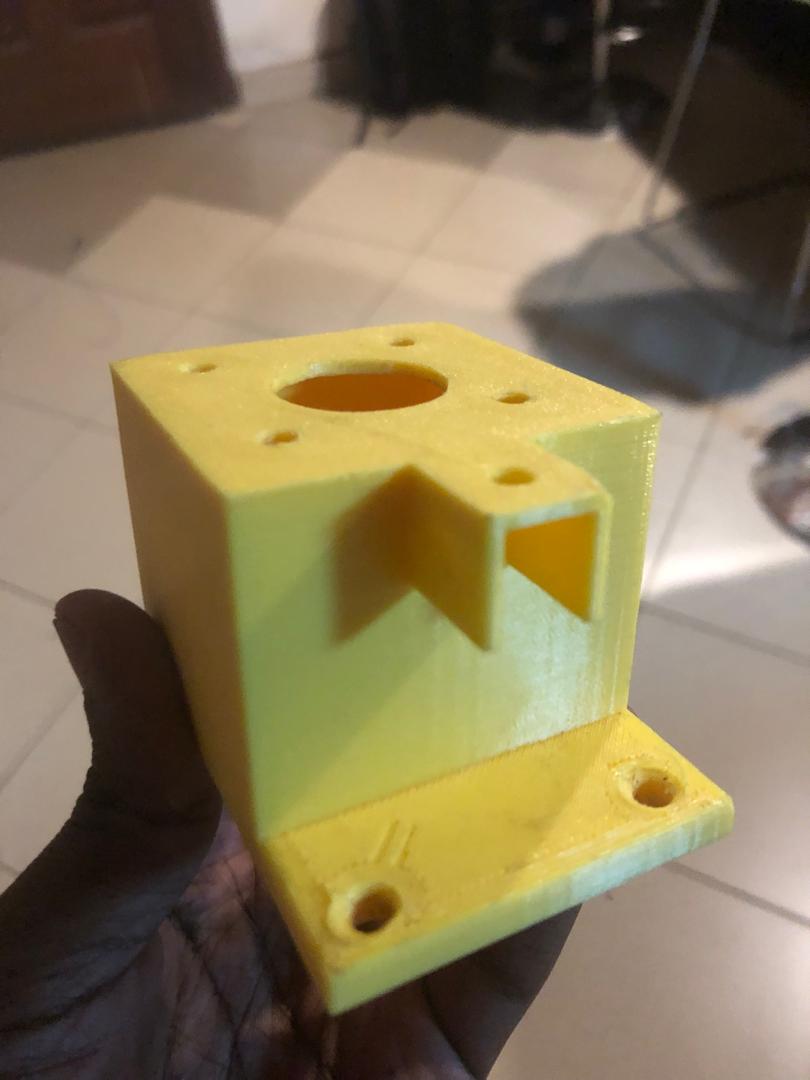
I then designed and milled the parts that will be static support of the z axis so since the x y coupler had a hole of 20mm
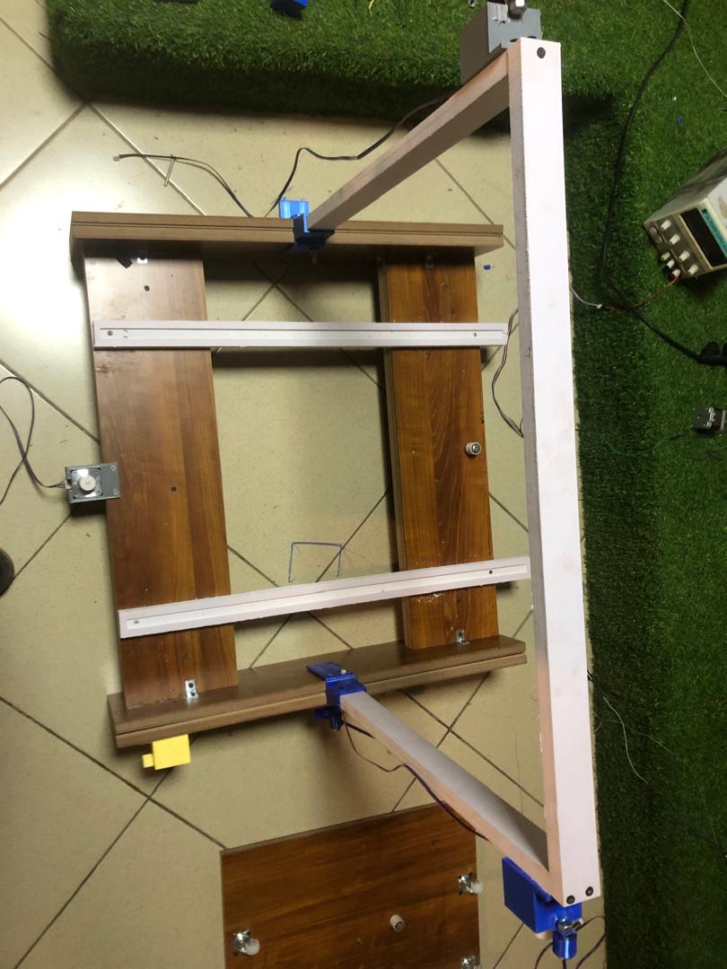
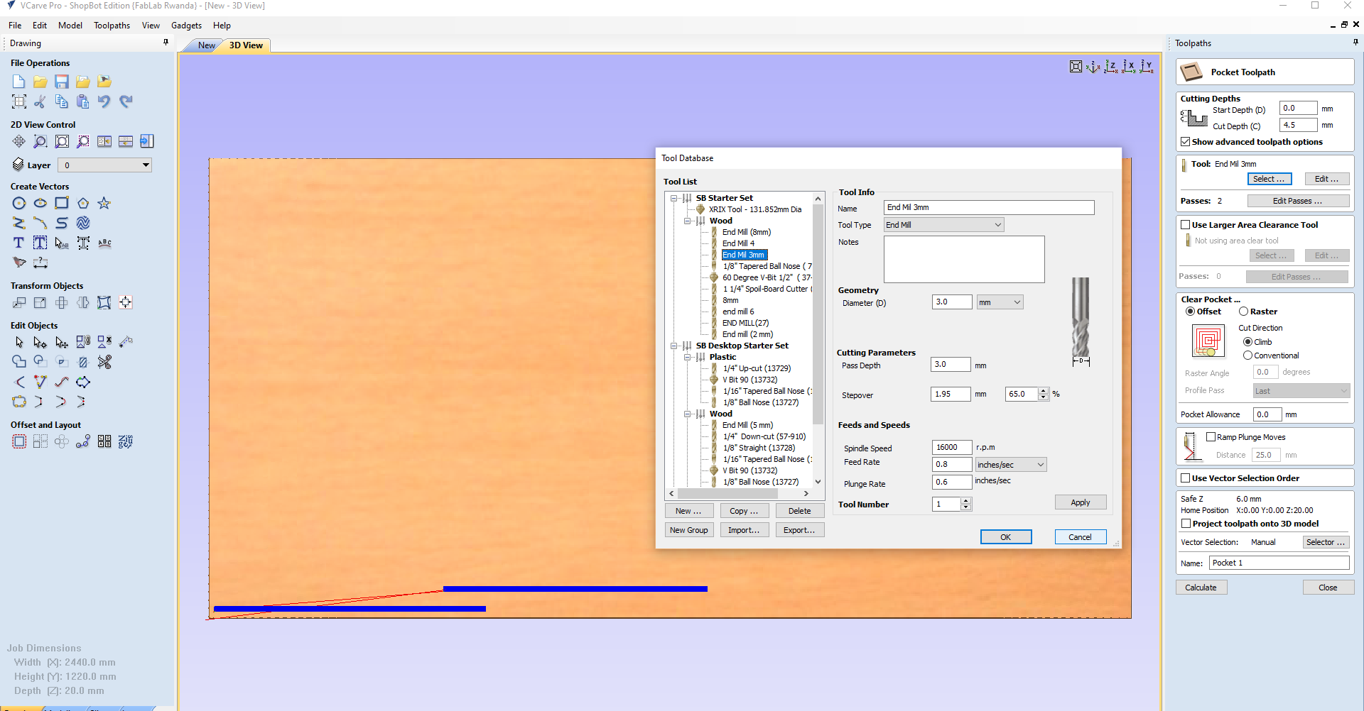
in which we will add the the z axis support then the material in which we mill these parts from had to be the same 20MM, so this 20mm thickness i had to use another material called foam board hence the white color material and since it was the same sheet i used i also cut the parts on which the bed will be sitting , so i cut pieces 2 two but i pocketed them before due to the wheels size of 1.6mm and the depth of 4.5MM
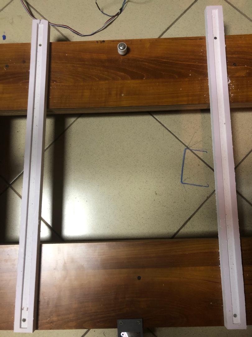
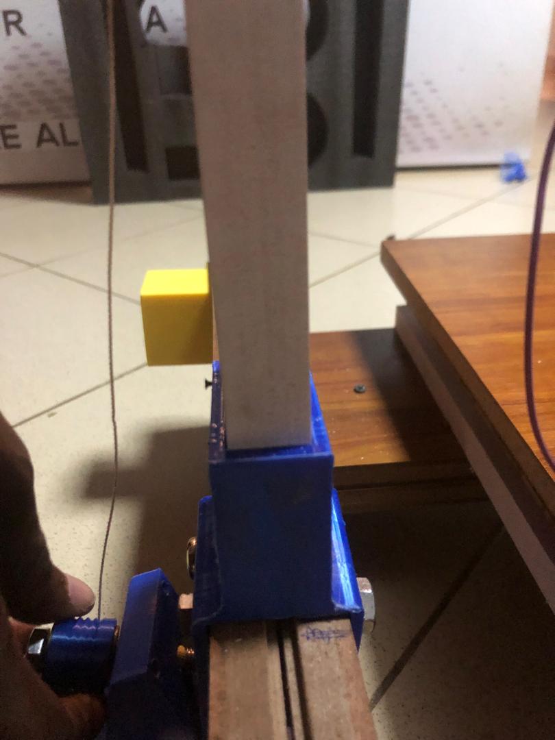

At last we add a base cut part of the machine on its bottom we added rollers in accordance with the pocketed parts that the rollers are going to be moving in back and forth


