-
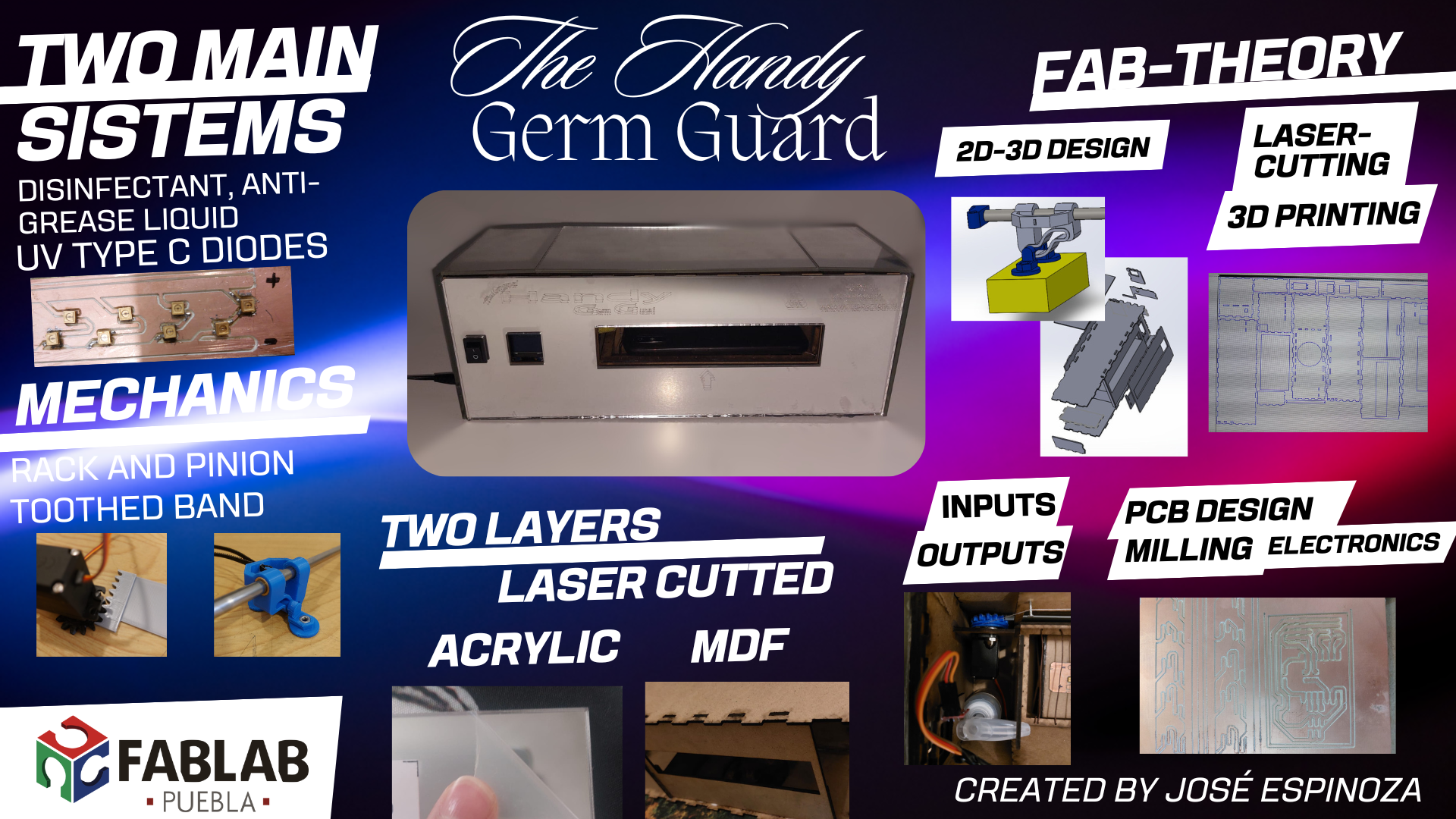
Project codename: [Handy Germ Guard]
Because of the main theme of this year fab i want to create something usefull at least, surfing the web I found many applications during coronaviruz for sterilizing all you can imagine, that gave me some ideas to create the Handy Germ Guard.
-
Quick travel
Presentation Video
First Ideas
There was a popular video (see the video) where a Japanese company began to include a small space where you can sterilize your phone in 30 seconds, eliminating 99.9% of bacteria, now we need to get rid of the rest of the indesired compounds that our phones retain.
My Idea
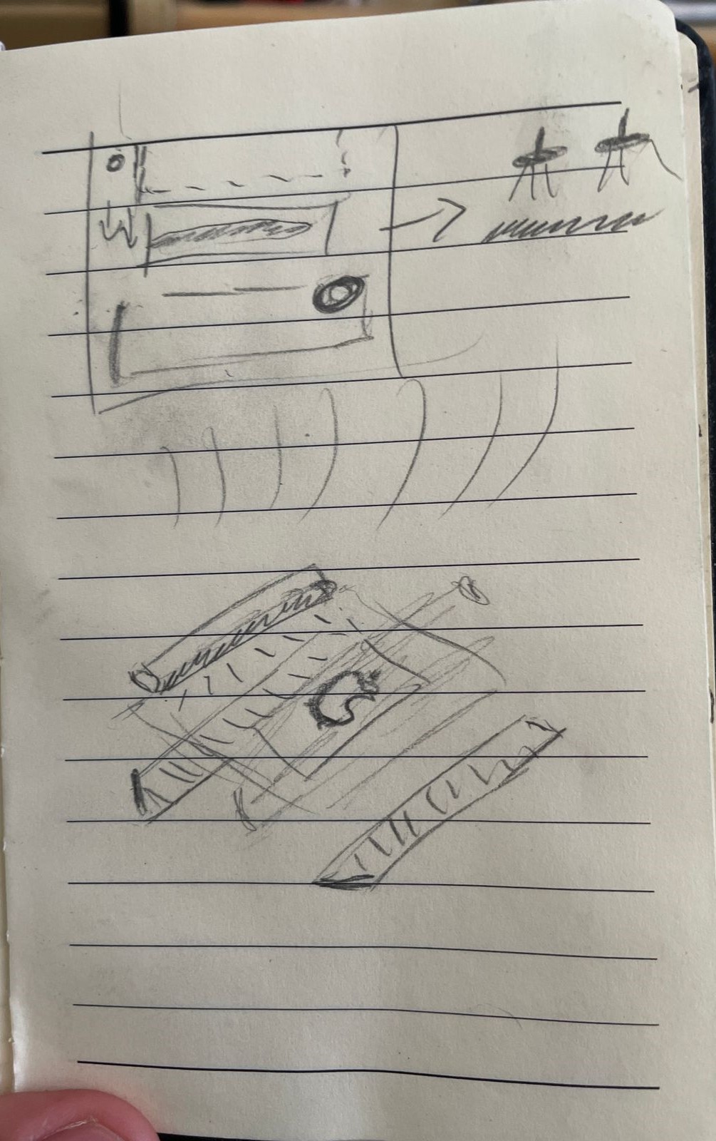
The general project scheme is like a common paper dispenser: the machine will take your phone in a specific way in order to give a special treatment to the face side. Inside, a UV disinfection process will occur within the first 15 seconds, and then the microfiber with a compound solution will clean and remove the heavy things from the front and back faces with the help of some rollers. In about 45 seconds, your phone will be 99% bacteria-, virus-, and fat-free. You could find this machine in every meeting centre, and with a nice design, it will fit even in the most luxurious places.
Answering the questions proposed in the first week:
- Target audience: The target could be every place with the number of adults enough, universities, shopping malls, sport centers, etcetera.
- Problem to solve: The number of different substances your phone carry in the day to day could help virus and infections to easily spread and harm you.
- Primary needs and pain points: You might think but it's as simple as buying phone wipes and having a cleaning habit, but no, if people forget to brush their teeth imagine their phone.
- Similar products and differentiative point: There are tons of similar products but they aren't safe enough, look at this video of the UV discussion as refference, also, the project has a different approach due to its ease of use and accessibility.
- How intuitive and user-friendly should be: I imagine it to be as simple as a toilet paper dispenser, that will help the project to easily adapt to predefined environments that didn’t initially have a designated place.
- Environmental impact: Another key point of this item is the ability to reuse microfiber towels, reducing the amount of paper and tissues used.
- Regulations and standards: I refer to this point when I say I’m not inventing a new UV disinfecting technic, the project will have applied only scientific tested examples.
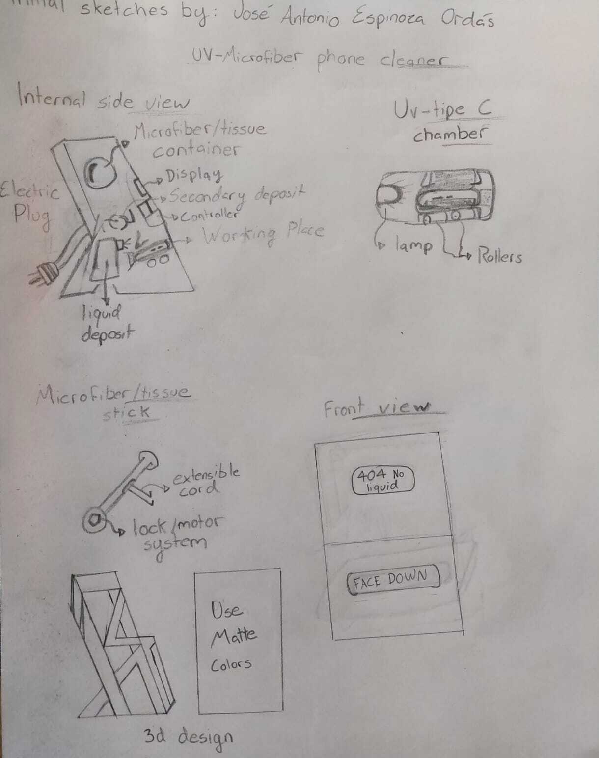
First sketches
The problem is that cell phones accumulate a lot of dirt, so we need a device that is in charge of disinfecting them. I have already seen that UV technology is very efficient for this, but I would like to add a way to clean the grease, so I need the system to include some way to spray some form of cleaner directly on the cell phone once inside, and it needs something that spreads it and cleans it, similar to a windshield wiper or that has a system of two rollers with microfibers to scrub it.
UV type-C
Like it's mentioned in the oficial philips page, just the Ultraviolet radiation has enough energy to break the chemical bonds between electrons and atoms. Therefore, it can be harmful to the eyes and skin (sun burns), but it is also beneficial for disinfecting surfaces and purifying the air.
We call UV type-C to the short-wave spectrum between 100 to 280 nm, UV-C works using a photolytic effect whereby the radiation inactivates the micro-organism so that it can no longer multiply. For DNA it does this by causing adjacent thymine bases to form a chemical bond thus creating a dimmer and if sufficient of these are created, DNA cannot replicate.
Viruses can live on surfaces for up to 5 days, so devices which come into regular contact or are shared between people can provide a higher risk just as everyone phones UV-C disinfection chambers are designed for the disinfection of objects.
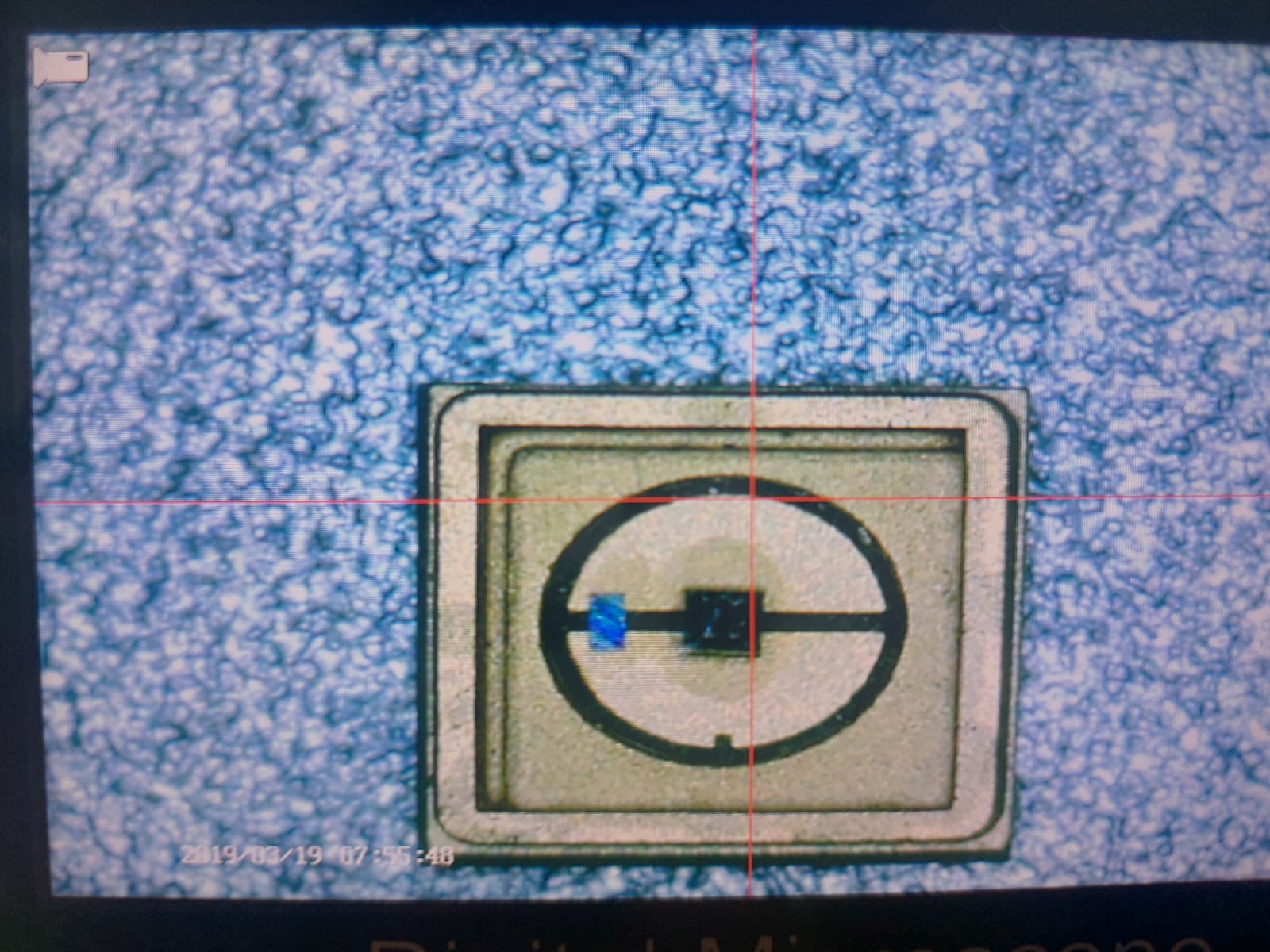
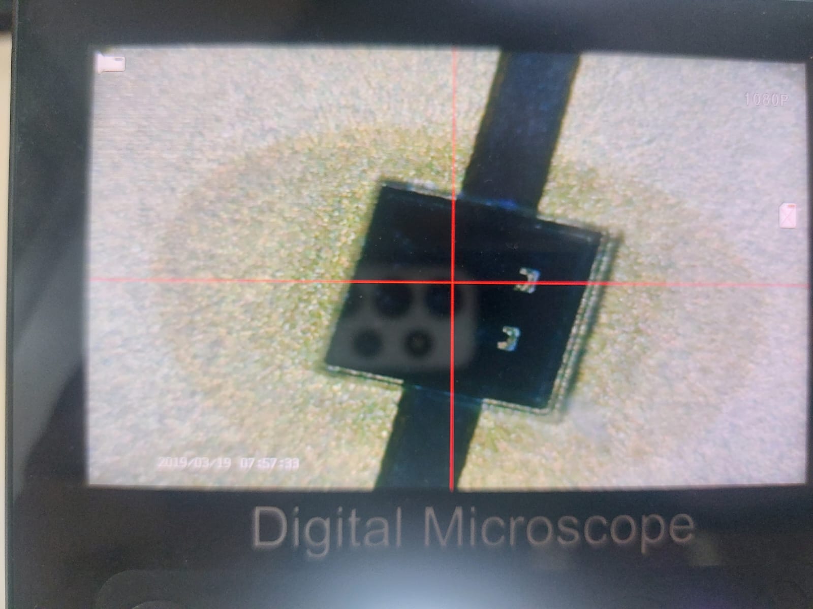
Looking for the diodes
I couldn't found a supplier of the diodes needed here in Mexico, or the ones that i found were to expensive, so looking through online markets if found them in alibaba,aliexpress, then contacted a supplier in alibaba that helped me deciding the amount and luminous power necessary.
They told me i would need an amount of 10 of the ones they recommend me but, the price tag of the shipper was really high so i searched for a solution that matched the amount of power needed resulting in 15 of the following Leds.
I bought 20 in total for the unexpected errors, they arrived 2 weeks later, from the next supplier: Buy the UV LED from aliexpress.
Mid term review
Progress in the first 11 weeks of the FAB Academy
| Task | Status | What progress did I make on my project? |
|---|---|---|
| Principles and practices | ✓ Completed | Make the webpage, Learnt about source control and usefull tools in web development |
| Project management | ✓ Completed | Learnt everything related to the UVC diodes and made some sketches |
| Computer-aided design | ✓ Completed | Made the first idea box a roller and some logos. |
| Computer-controlled cutting | ✓ Completed | Learnt to laser cut, engraving and kerf. |
| Electronics production | ✓ Completed | Learnt about electronic components and how to make PCBs |
| 3D scanning and printing | ✓ Completed | Learnt to make special one print two pieces set and parameters. |
| Electronics design | ✓ Completed | Master soldering and creating my own designs of PCBs |
| Computer-controlled machining | ✓ Completed | Learnt how to make mdf structures |
| Embedded programming | ✓ Completed | Checked a language for my final project "Arduino IDE" |
| Output devices | ✓ Completed | Test many motors and the Oled screen for the interface |
| Mechanical design and machine design | ✓ Completed | Learnt about Rack and pinions and toothed bands, mechanical energy distribution |
the truth is that I did not have much idea about mechanical things so I was not taking into account many aspects that were the ones that would define the physical dimensions of my project, thanks to the output week and the design of machines and mechanisms I realized that I have to change the way my project works, because if in team in these two weeks we cost to implement different systems, my initial idea of using rolls and creating a reflective camera with leds in different places I see it complicated to do it in a few months, the good thing is that now I have a clearer perspective of how to make it reality.
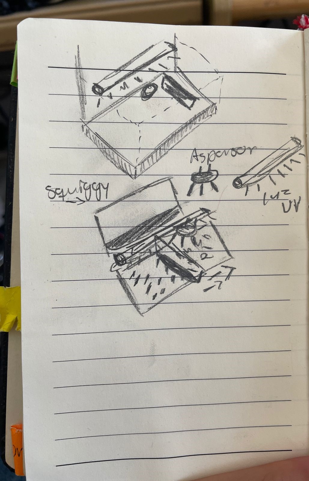
Change of the main idea:
My main idea was to create a two-roller mechanism with rolled microfiber that would quickly pass over the surfaces of the phones like a car wash, but after the CNC week I realized that what I had to do was another way where the cell phone would enter and there would be a door and a sweep.

project operations schedule
| Date | Task |
|---|---|
| Wednesday, April 10 | Learn about the Input devices and choose two for mi final project |
| Wednesday, April 17 | Design the new system including all modular parts |
| Wednesday, April 24 | Cut MDF and print the necessary parts |
| Wednesday, May 1 | Design and make all the PCBs |
| Wednesday, May 8 | Assemble the sweep and Rack and pinion systems |
| Wednesday, May 15 | Assemble all the other components and the ejection system |
| Wednesday, May 22 | Finish all the Embedded programming |
| Wednesday, May 29 | make several cosmetic improvements and cable management |
| Wednesday, June 5 | final presentation |
Giving life to my idea
Every week helped building this project and all the files used to build this project are gathered here: The Final Zip
This zip contains a group of folders to help you know the process needed to make the parts, the .dxf are designed to be cut with laser, the xiao files are meant for the electronics productions and the 3D print are the .stl or .3mf files for you to 3D print.
Making the structure
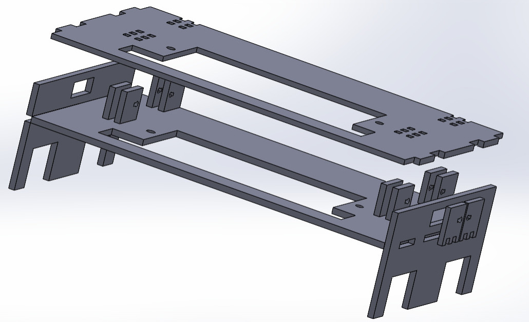
The initial case made during week2 needed to be replaced with a more integrated one, during week16 i remade the idea in order to have a complete system integration.
With all the pieces, I designed and built a press fit system where everything fit together and screwed the components together.
Electronics Design, Production and Soldering
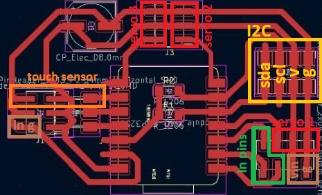
Im using a variant of the board made during week11, the advantage of using a xiao is that in a small space they include an internal voltage regulator, a large amount of flash and sram memory, and a very high clock speed for fast communications between devices, in case you have I2C communication it is necessary to include resistors in the SDA and SCL channels, as for the PCB design I learned that it is worthwhile to add a ground and voltage pin for each digital output on practically any board, to control the servo motors it is necessary to include a capacitor with a higher voltage than they consume and the higher the capacitance the better.
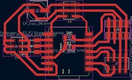
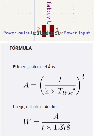
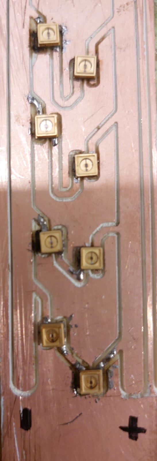
I also had to design a board to power the LEDs, thanks to the tools included in Kicad it was very easy to create the track and footprint for my UV diodes with a total of 10, initially I was thinking of including one ohm resistors since these consumed between 5.5 and 7 volts and 25mA but a teacher told me it was unnecessary since that is practically the resistance of the cables, so my parallel LED matrix consumes 125mA, The width of the lines is due to the fact that the LEDs did not come with a single data sheet but a general one, so we thought that they were going to consume quite a bit more current and therefore, following the formula shown below, they needed a width of that size.
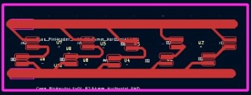
Following the same steps from the previous weeks of electronics, I used the Roland SRM-20 to produce both boards, then soldered female pins for the Xiao and male pins for the others, in addition to the capacitor.
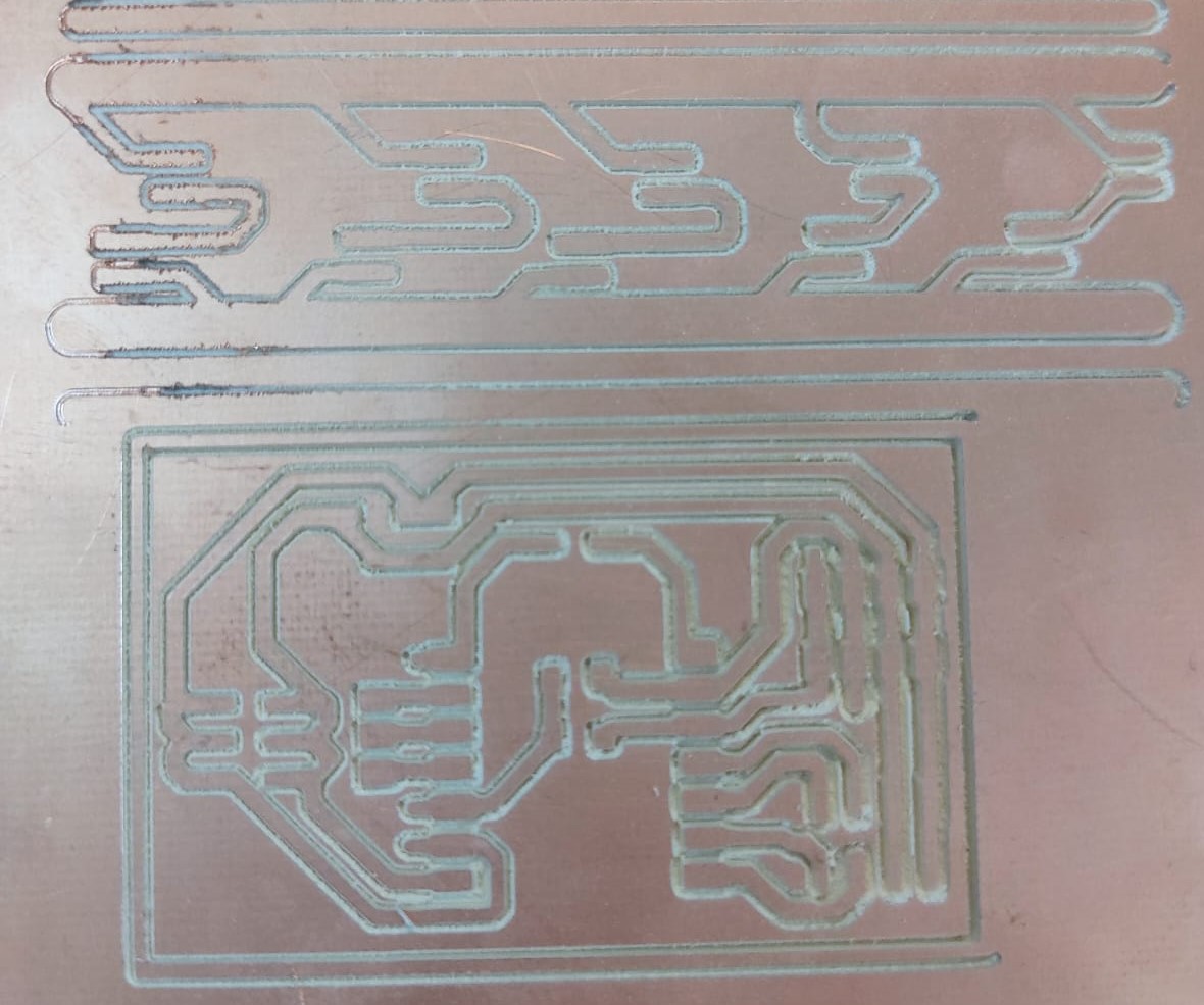
I do not recommend anyone to solder these diodes with the soldering iron technique, it easily took about 2 hours because the tin was easily passed from the cathode to the anode, I would recommend if you have solder paste applied with a heat gun.
Pinout of the main PCB
Mechanical Systems
I did the motors testing during week9 there you can see my opinions.
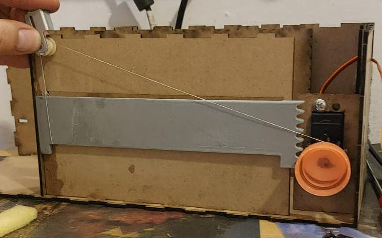
toothed band for the sweep design
Test code: servo.ino.
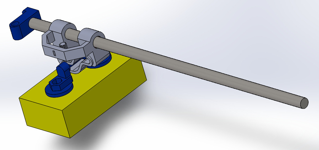
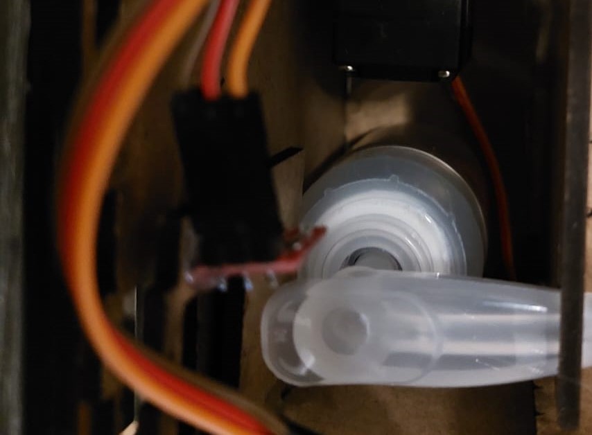
For the operation of the toothed belt, I designed a tube holder mounted on a motor support, and the piece that will make the journey, holding the sponge, needed space for nuts and a system that could be printed in one piece. This system had to have space to go up to the phone and hold onto the toothed belt at the top.
I had to sand the surface of the piece that was going to move a little so that the bushings would fit, while the black piece fit perfectly.
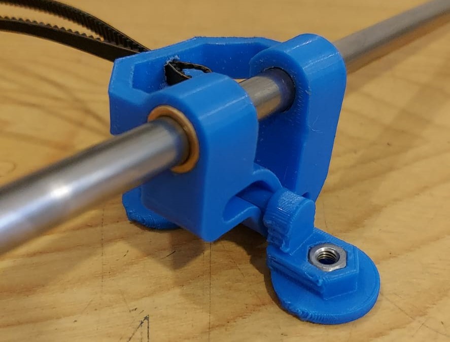
One problem I encountered when assembling was aligning the toothed band and the ends of the tube, I had to use a series of washers on both sides
Testing the movement when fully assembled
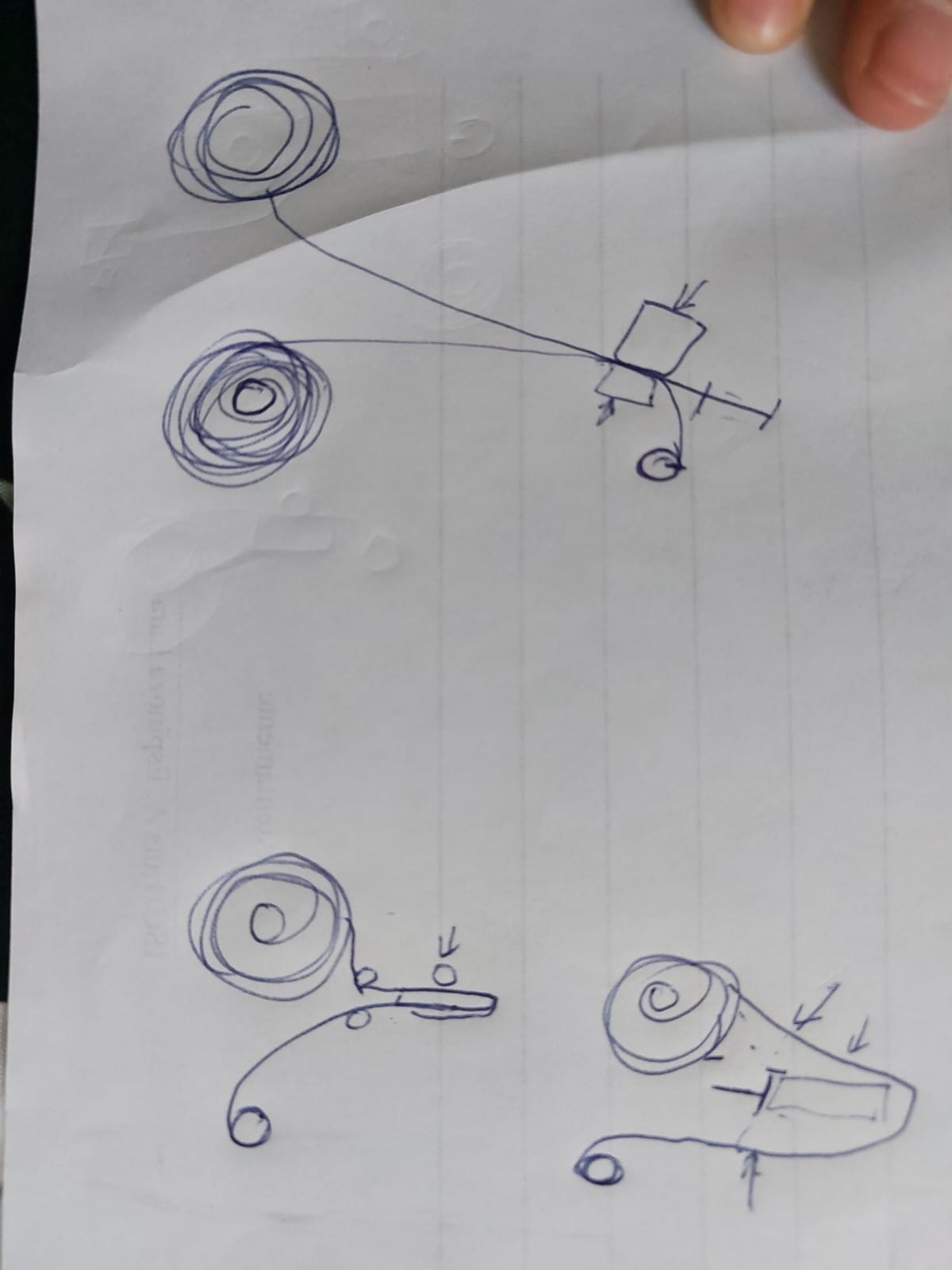
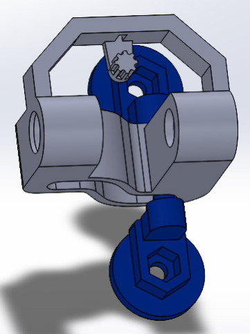
Rack and pinion system
Test code: servo2.ino.
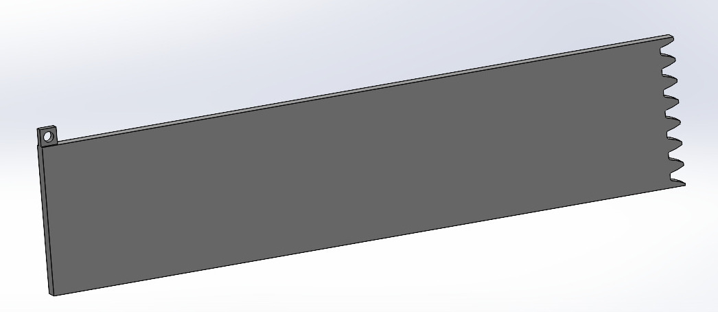
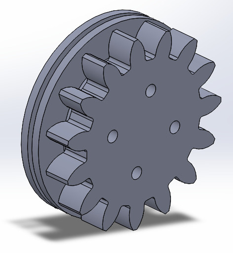
In this part I was initially wrong thinking that the friction of the door would be enough to compensate for not having force in that part, another observation that I saw during the tests was that the servo base library would not work for the size of my gear while in the esp32 I have 20 degrees to spare.
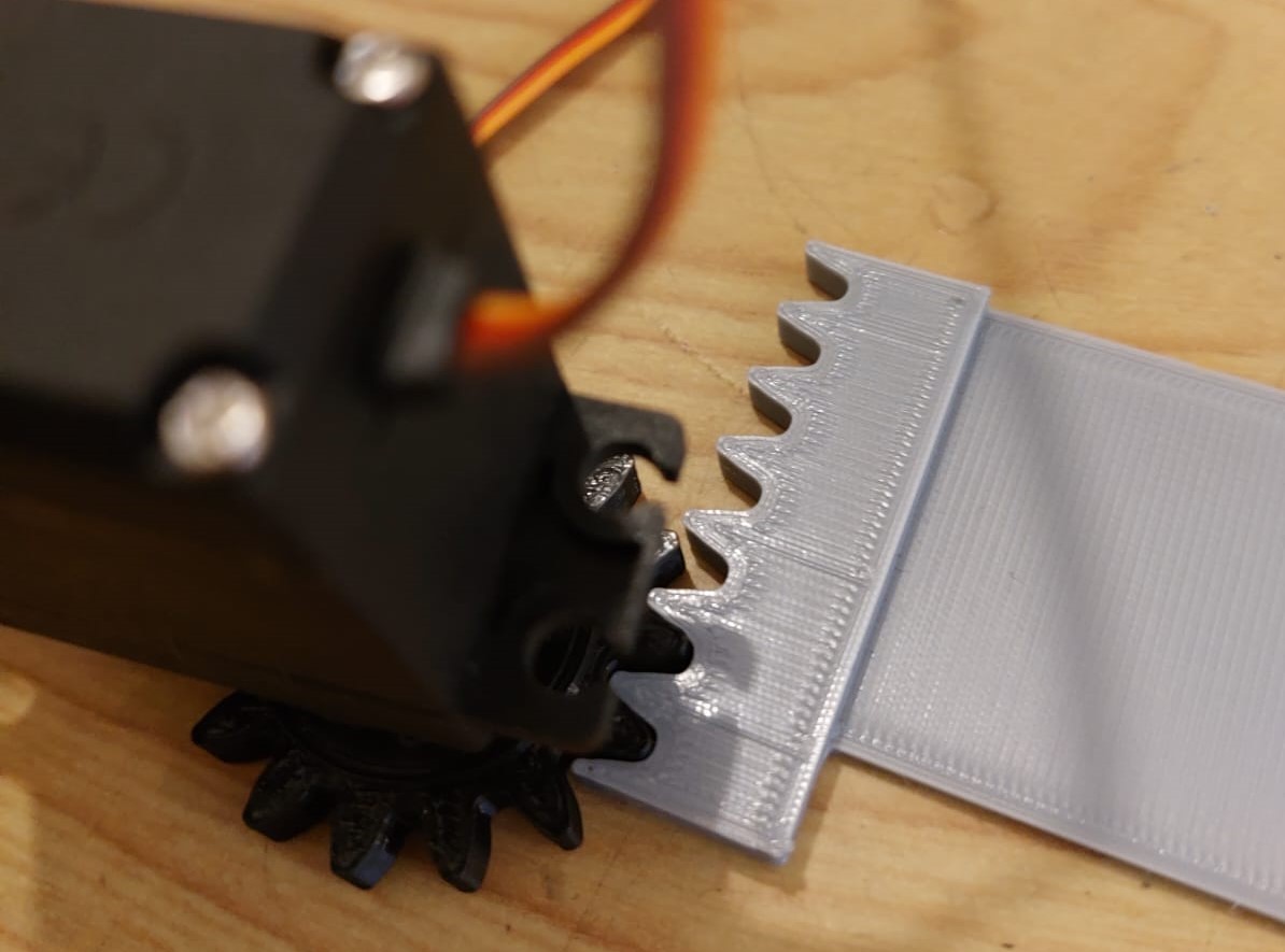
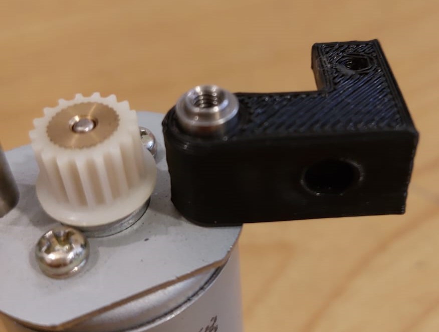
Clearly it didn't work so I had to find a way to get the driving force to the other end of the door, using thread I saw that I had space behind the gear so I modified both pieces as shown in the start of the section and that solved the problem.
Bed design
Test code: servo2.ino.
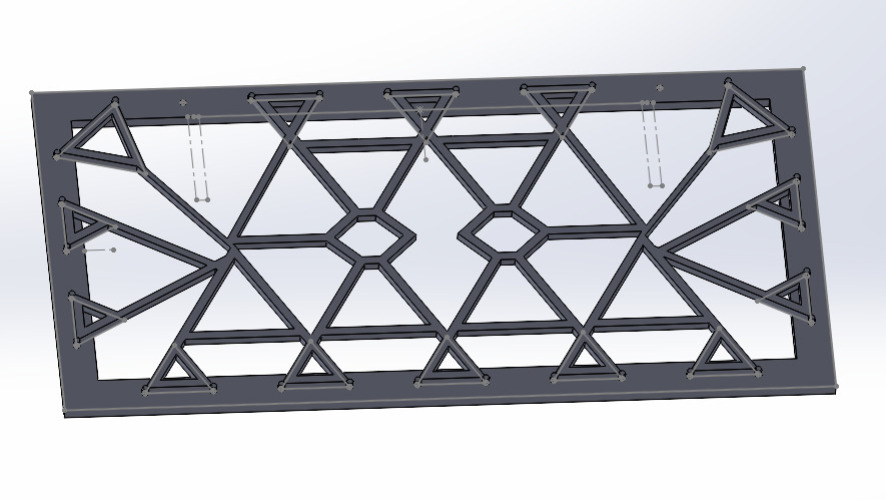
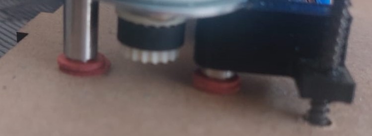
At first I thought I would find a material that was permissive with UVC radiation to use as a bed, like glass, but during my research, as I was unable to find a UVC sensor that I could afford for the project, I searched on the Internet and found a video [link] in which a glass was used to show the reduction of radiation, so at first I used a wire to join the dots and then my instructor recommended that even if there were losses, I should make a pattern.
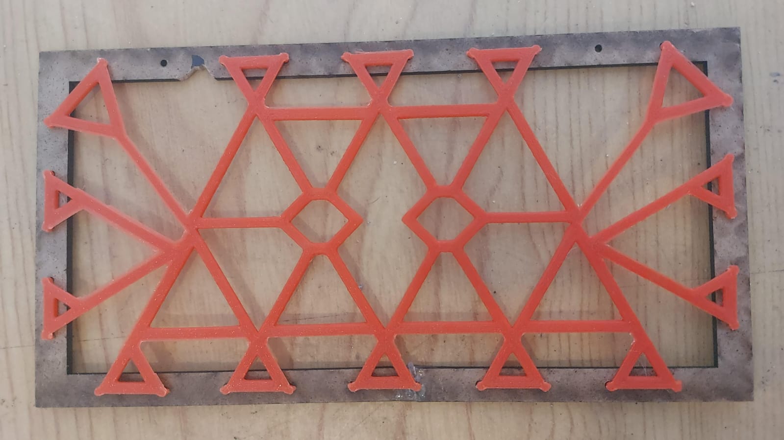
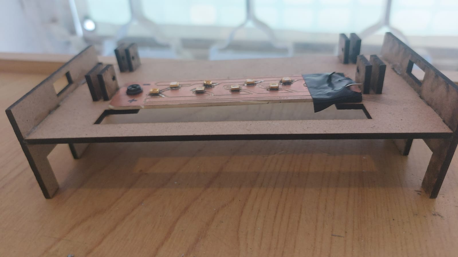
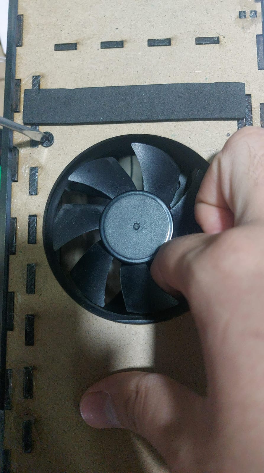
There's enough space in my pattern for the servo hands to pull out the phone, in the design i considered enough space for the fan and the related wires, so when you find yourself adjusting the fan make sure to put it as sticky as possible, surprisingly no need to use screws to adjust the servers, the only problem I found was they weren't identical and one had a largest hand.
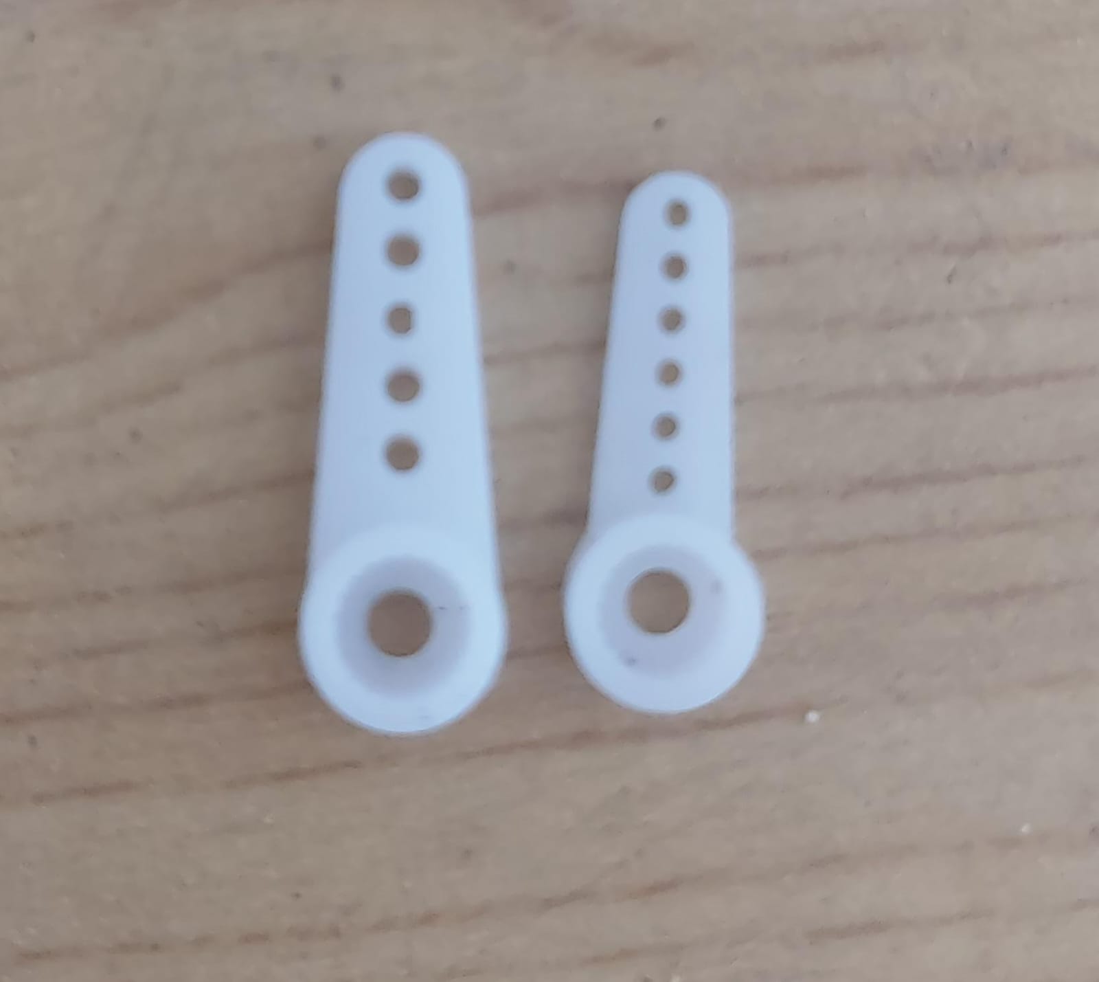
With the servos placed, loaded the code servo2.ino in the Xiao you can see them working, because of the servos are different the phone goes to one side, but it works, another point that could be optimized is to turn a server and use the same signal saving a pin, although the diodes would not be centered.
Inputs
I did many tests during the week11 for diferent inputs to use in my final project.
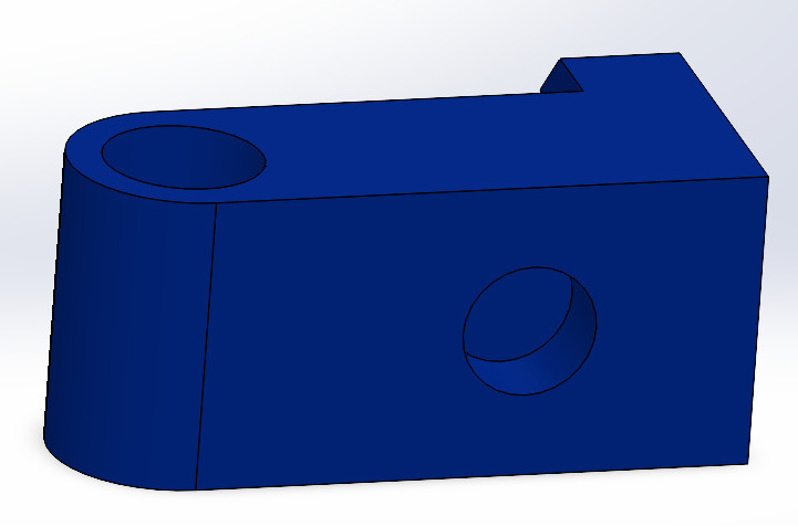
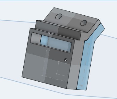
I've decided to use a touch sensor that is attached to the side where the bottle has to be pressed and a VL53L0X time-of-flight sensor, as it is in direct contact at times with the sponge, it needed a case.

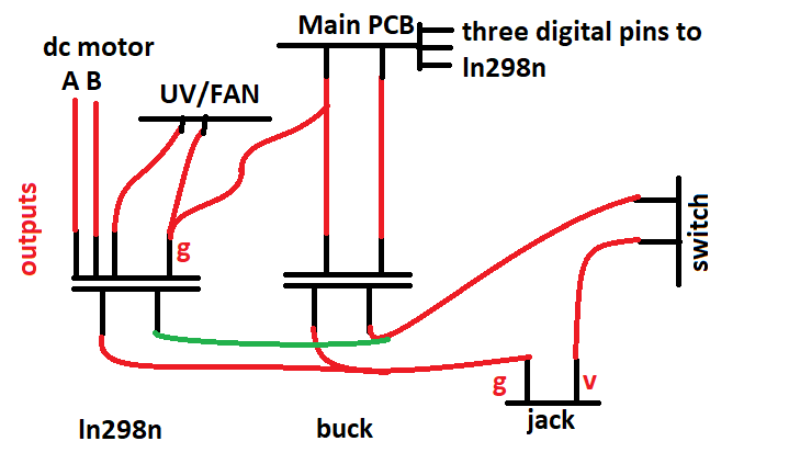
Electrical system and 12V Output control
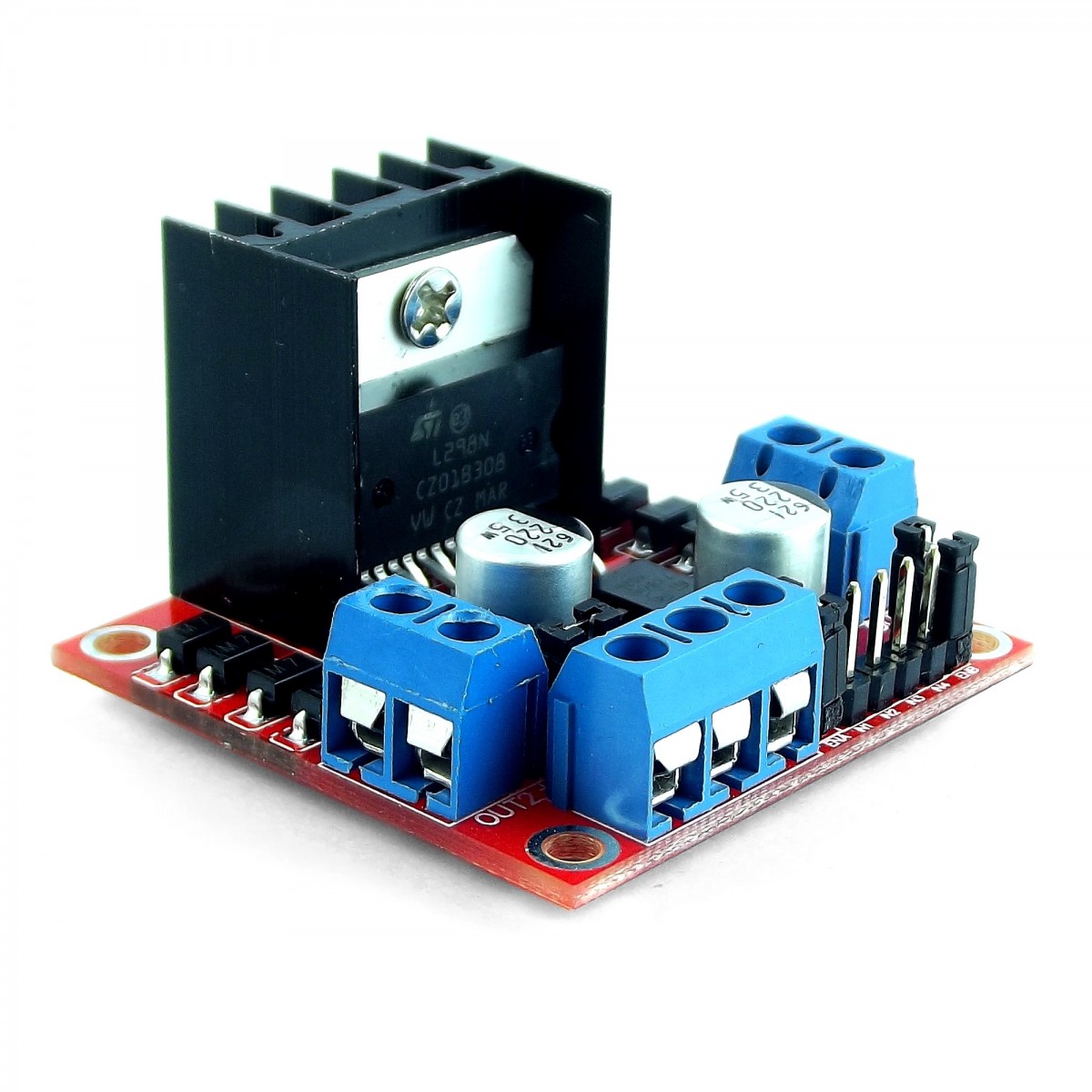
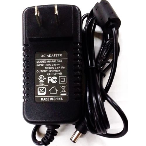
In the electrical part of my project I needed a 12V 2A power supply, it turned out that my motor was relatively small and did not consume more than 400ma during my tests, then I needed a 4-output controller the ln298n can control up to 30V with 4 signals from the microcontroller, I also needed a switch and an inverted jack, below are the connections:
Final Embedded programming
VL530X Test code: Single.ino. Oled Test code: oled.ino. Final code: final.ino.
As a future software engineer i understand a diagram can help understanding the code and making it easier to code, then here is a diagram that turned out to be quite linear.
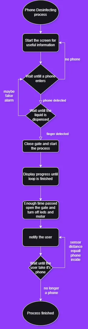
Like I mentioned in my project plan week17 the full process required the cooperation from all the parts of the project, the compilation of the small codes build the final code with the addition of helpfull interface outputs for the user in the OLED screen.
#include "Wire.h" //I2C library
#include "VL53L0X.h" //Polulu library for this sensor
#include "ESP32Servo.h" //Servo handle for esp32 family
#include "Adafruit_GFX.h" //Oled screen libraries
#include "Adafruit_SSD1306.h"

const int touchsens = D10;
const int ventilador = D2;
const int motorPin1 = D0;  // Pin 0 connected to IN1 on the L298N
const int motorPin2 = D1; // Pin 1 connected to IN2 on the L298N
const int duration = 400;  // Duration to keep the pin HIGH in milliseconds

int pos = 0;

VL53L0X sensor;
#define HIGH_ACCURACY

Servo myservo;  // create servo object to control a servo

const int myPos = 20;  // define the step size
const int maxPos = 160;   // maximum servo angle

#define SCREEN_WIDTH 128
#define SCREEN_HEIGHT 64
#define OLED_RESET     -1
Adafruit_SSD1306 display(SCREEN_WIDTH, SCREEN_HEIGHT, &Wire, OLED_RESET);

int progress = 0; // progress of the progressbar

unsigned long previousMillis = 0;
const long interval = 4200; // Interval in milliseconds

void setup() {
  myservo.attach(D6);
  myservo.write(pos);
  pinMode(touchsens,INPUT);
  pinMode(ventilador,OUTPUT);
  pinMode(motorPin1, OUTPUT);
  pinMode(motorPin2, OUTPUT);
  #if defined HIGH_ACCURACY
  sensor.setMeasurementTimingBudget(200000);
  #endif
}

void loop() {
  //Start
  pos = maxPos;
  myservo.write(pos);
  display.clearDisplay();
  display.drawBitmap(0, 0, myBitmap, SCREEN_WIDTH, SCREEN_HEIGHT, SSD1306_WHITE);
  display.display();
  delay(2000);
  display.clearDisplay();
  // Set text size and color
  display.setTextSize(1);
  display.setTextColor(SSD1306_WHITE);
  // Display the text
  display.setCursor(0, 0); // Set cursor to top-left corner
  display.println("Hello!!!");
  display.println("Please put your");
  display.println("phone through");
  display.println("the wall");
  display.display();
  delay(3000);

  //PROCCESS AREA
  while (vals < 141){
    (sensor.readRangeSingleMillimeters());
    //No need for a delay as the library already includes and need one for better takes
  }
  display.clearDisplay();
  // Set text size and color
  display.setTextSize(1);
  display.setTextColor(SSD1306_WHITE);
  // Display the text
  display.setCursor(0, 0); // Set cursor to top-left corner
  display.println("Now please");
  display.println("Spray the liquid");
  display.println("on the right side");
  display.display();
  int val = digitalRead(touchsens);
  while(val != HIGH){}
  digitalWrite(ventilador,HIGH);
  pos = myPos;
  myservo.write(pos);  // move the servo to the new position
  while(progress < 101) {
    unsigned long currentMillis = millis();
    if (currentMillis - previousMillis >= interval) {
            previousMillis = currentMillis;

            display.clearDisplay(); // Clear the display buffer
            display.drawRect(12, 21, 104, 20, WHITE);
            display.fillRect(14, 23, progress, 16, WHITE); // draw the progressbar fill
            display.setTextSize(1);
            display.setTextColor(WHITE);
            display.setCursor(33, 53);
            display.print(F("Progress: "));
            display.print(progress);
            display.print(F("%"));
            display.setTextSize(1);
            display.setTextColor(WHITE);
            display.setCursor(0, 7);
            display.println(F("Progress Bar Screen"));
            display.display(); // Display the content in the buffer

            progress++;
        }
    }
    //Finish
    progress = 0;
    digitalWrite(ventilador,LOW);
    val = LOW;
    pos = maxPos;
    myservo.write(pos);
    int vals2 = sensor.readRangeContinuousMillimeters();
    while(vals2<=vals){
      vals2 = sensor.readRangeContinuousMillimeters();
    }
  }
Final Details [Acrylic Case]
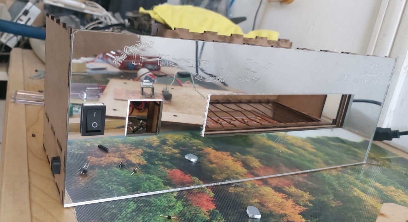
For a final project I couldn't leave it with exposed mdf so I asked my teacher if it was a better option to change the structure for acrylic or make a second case, as it turned out to be the second option I made a design in solidoworks with everything and engravings, the files are in the acrylic .dxf folder.
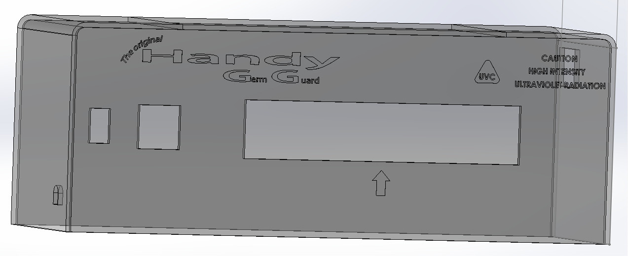
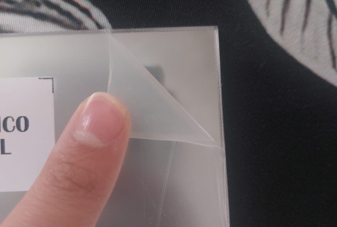
Since the acrylic was going to be the outer layer of the project, I decided that a mirror-like material would look good. The acrylic came with its own protection to prevent scratches, and when cutting it, it had to be done from below so that the laser wouldn't reflect. I then tried to use thermoforming techniques, but I think the machine was undergoing maintenance at the fab, so I had to make the cuts and it no longer turned with rounded corners.
Some pieces like the switch had to go on top of the acrylic, so until the acrylic arrived I couldn't finish the project.
Final Bill of materials
| Name | Description | Number | Unit Price MXN | Total MXN |
|---|---|---|---|---|
| 2PCS 3535 UVC LED Lamp Beads for UV Disinfection Equipment | 265-285nm SMD Chip LED Deep Violet Ultraviolet Lights Diode 1W 2W | 5 | $17,64/ lot | $88,20 |
| Capacitor | for the start of the servos, 16V 470uF | 2 | $7 piece | $14 |
| female pins | for the microcontroller | 7 | $2 piece | $14 |
| pins | for the PCBs | 30 | $5 lot | $5 |
| Acrylic mirrored | 40x60cm in 3mm width | 1 | $254 piece | $254 |
| Xiao esp32c3 | Powerfull, small and economic microcontroller | 1 | $200 piece | $200 |
| female-female dupoint wire | for connections between devices | 16 | $25 lot | $25 |
| Extra cord | Less than a meter needed to extend and make exact lenght wire | 1 | $10 piece | $10 |
| black tape | To protect wire joints, not much required | 1 | $80 piece | $20 |
| PLA filament | For the 3d printed pieces | 100g | $500 piece | $150 |
| 3mm mdf plate | 61x122cm in 3mm width. | 1 | $44.5 plate | $44.5 |
| Oled screen | Generic Oled screen for electronic projects | 1 | $95 piece | $95 |
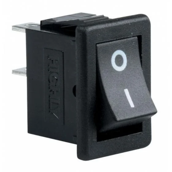
| Miniature rocker switch, 1 pole, 1 throw, 2 positions | Main power switch | 1 | $9.00 piece | $9 |
| L298N | Driver that handles 4 outputs with 4 signals introduced | 1 | $55 piece | $55 |
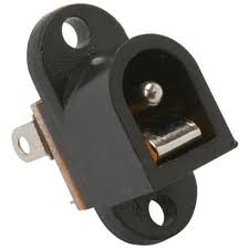
| 2.1 mm inverted jack for chassis | To input the power supply | 1 | $5 piece | $5 |
| motor 12V dc 140RPM | Main motor used in the sweep system | 1 | $180 piece | $180 |
| MG995 High Speed Digital Servo Motor | With Torque at 6 V 12 kg | 1 | $111.33 piece | $111.33 |
| Micro Servo Motor SG90 | Locked rotor torque: 1.2-1.4 kg/cm (4.8V) | 2 | $37 piece | $74 |
| Closed Band, 400mm GT2 Closed Timing Belt for 6mm and motor pulley | Needs to match with the motor and the pulley | 1 | $130 piece | $130 |
| sponge | to attatch to the sweep | 1 | $17 piece | $17 |
| Plastic pulley for 6mm with screw-on base | Need to match with motor no more than 14mm outside | 1 | $40 piece | $40 |
| screw posts | to match the height of the pulley and the motor pulley to attatch to the roof with secrews | 2 | $10 piece | $20 |
| 304 Stainless Steel Solid Round Rod | 6mm x 300mm | 1 | $68.4 piece | $68.4 |
| Self-lubricating composite bearing copper shaft bushing, small inner diameter, 6mm | To attach the 3D printed piece to the rod | 2 | $15 piece | $30 |
| 10cm x 15cm phenolic plate | for the PCBs | 1 | $29 piece | $29 |
| Touch sensor TTP223B | To detect the spray action | 1 | $20 piece | $20 |
| VL53L0X laser distance sensor | Time-of-flight (ToF) sensor designed to measure close distances | 1 | $100 piece | $100 |
| 30ml spray bottle | for the liquid | 1 | $40 piece | $40 |
| 12V Fan with screws | for the cooling of the leds | 1 | $70 piece | $70 |
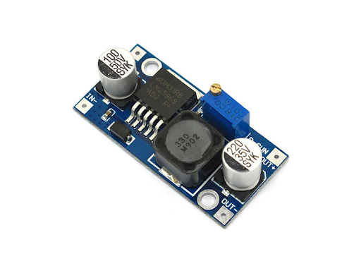
| Buck converter LM2596 | Get a lower voltaje from the 12V Input to 5V | 1 | $26 piece | $26 |
| Power Supply | 12V, 2A, 2.6mm jack | 1 | $120 piece | $120 |
| washers | more small posible | 2 | $1 piece | $2 |
| nails and wire | to set the sensor case and wire | 3 | $1 piece | $3 |
| nuts with bolts | 14mm lenght, m3 | 10 | $5 lot | $5 |
| screws | 5mm lenght, m3 to fix the PCBs | 4 | $1 piece | $4 |
| straps and 3 x 3 cm self-adhesive bases | for wire managment | 2, 4 | $10 lot | $10 |
| MXN to Dolar: 0.055 | MXN$2000 US$110 | |||
System Integration
The main objetive talking about system integration is to achieve a long-lasting project, we achieved this with many techniques applied in week 16, but in summary what we are looking for is that it does not look like a Christmas present with the contents clashing with each other.
Intellectual Property and future posibilities
The full breakdown about this themes is reviewed on the 18th week, where i define the future scope of my project and the license choosed to achieve my goals:
Handy Germ Guard by José Antonio Espinoza Ordás is licensed under
CC BY-NC-SA 4.0
![]()
![]()
![]()
![]()