9. Output devices
There are many output devices, im curious to test different kinds of motors, because applying different strategies, you can automate almost every mechanical thing, I also want to add a LCD or Oled screen as well with my UV leds.
In the group page you can find the information related to meassuring the power consumption of different motors: Group assignment.
The comprehension of a motor's power, voltage, and current specifications is imperative for several critical reasons. Firstly, it ensures compatibility with the electrical supply and the integrity of the electrical circuit, mitigating the risk of damage due to inappropriate voltage levels or excessive current flow. Secondly, it facilitates the correct selection of protective devices such as fuses and circuit breakers, which are essential for preventing electrical hazards. Thirdly, these parameters are integral to the calculation of energy efficiency and operational expenditure, which are paramount for economic feasibility and environmental sustainability. Lastly, precise knowledge of these specifications is indispensable to avoid a fight between the components for the current and is always recommended to keep some gap between the consumption of the circuit and the max current of your power source.
There are also very bad practices such as control motors directly from the microcontroller, exhausting the maximum current that these can take out of each pin, for example for most xiao and arduino it's recommended that you do not pass 80mA per pin and 200mA in total when a motor can easily reach to occupy 100mA for a pin, while to power a led using the law of ohm you can generate arrays as long as you keep the pins around 40mA that is the recommended.
The PCB
Using the board fabricated in Week 8 i will try to program the outputs, but i think i will need a powerfull one for my final project, probably a xiao based, as i already know the advantages of those 'modules'.
First output: The Servo motor
This week Servo control by servo.h in arduino: oneservo.ino.
Two servos and a potenciometer in arduino: 2servos.ino.
This kind of motor is useful for it's ease of use, the number of outputs required and the minimal infraestructure needed, with this kind of motor is easy to control the angular position, steps or cycles; i found the next image in the web, that shows the relevant information from the full datasheet.
-
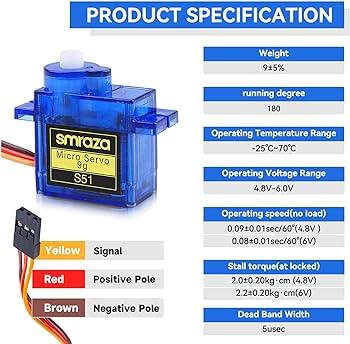
1. Weight: This is just the weight of the motor not including the plastic wings.
2. Running degree: This servo goes from 0° to 180° in the full movement, they often break or get electronic burn if you manually force the wings, be really carefull!
3. Operating Voltage range: Deppending of the force needed the servo will use more or less V in the range mentioned, as shown in the operating speed, the name of micro servo 9g often refers to the amount of load that can move.
4. Dead bandwidth: is a way to say how accurate the servo holds its position. Suppose a servo has a dead bandwidth of 5usec (microsecond) and a command is sent to center a servo.
A bigger one
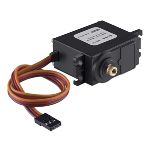
- Torque: 10 kgf/cm at 6 Vcc
- Rotation: 180°
- Voltage: 4,5 - 6 Vcc 200 mA
- Speed operation: 0,16 s
- Weight: 58 g
- Dimensions: 40,5 x 20 x 45,4 mm
-
Connections:
The red wire is for the voltage imput, the brown is for the ground and the yellow for the signal needed, you need to connect it to a analog PWM type of output in your schematic, depending of the accuracy and precision of the pulse needed for the aplication of the motor you might need to add a faster crystal oscilator in your design, as the attiny44a-ssu and many others come with a 1 or 8 MHZ internal oscilator and those are capable to work with an external up to 20MHZ.
The problem mentioned above applies to all the outputs that require a PWM signal, as that's the way the microcontroller is able to send variable signals.
Plastic wings
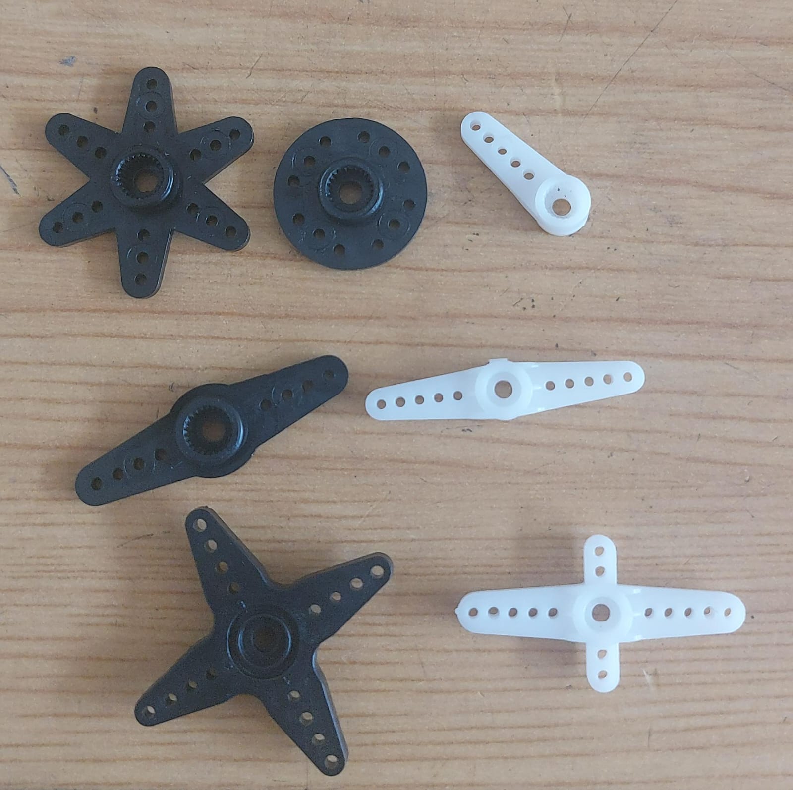
They come with every servo and are useful to attach other things with the help of screws, something to have in mind is that the weight they mention to work with is when you use the holes near to the center as more torque will be need, therefore can move less weight.
The black parts are bigger in general and the top gear is bigger too so that the white ones doesn't fit in the black servo
The main difference between the blue and the black is the material of the gears, plastic vs metal, the black is four times bigger than the blue, as well the amount of noise they make.
The code
Attiny44a-SSU pinout
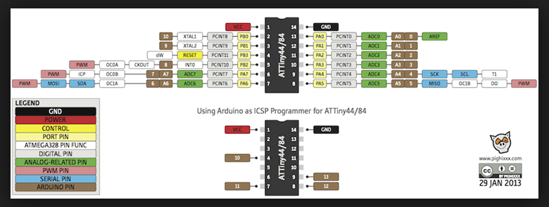
Board connections
-
The simple sweep example
The simple way to learn and code, is with arduino IDE, it's not the optimal way but there's no place for importing libraries like arduino ide, so the steps are include library, create a special servo object, attach to the PWM pin number and write the position using write(angle) to send any postition between 0 and 180.
-
#include "Servo.h" //Library for the servo object and PWM function
Servo blue_servo; //Name your servo
int angle = 0; //Save the position
void setup() {
	blue_servo.attach(6); //Place of the servo
	blue_servo.write(angle); //Return to 0
}
void loop()
{
	// move in little steps of 1° until reaching the end
	for(angle = 0; angle < 180; angle++)
	{
	blue_servo.write(angle);
	//add a delay to wait for the servo to arrive
	//add more time when moving more distance
	delay(15);
	}
	// move back in little steps of 1°
	for(angle = 180; angle > 10; angle--)
  {
    blue_servo.write(angle);
    delay(15);
  }
}
-
Hero shoots
For this an other hero-shoots for the electronic weeks im using a PC power supply for a 3.3V, 5V or 12V output deppending on the logic Voltage of the microcontroller and the consumption of the outputs and inputs, the power supply can suministrate up to 25 A on each channel.
For my surprise the attiny can handle servo move smoothly, during the learn of this week my attiny suddenly stopped working, eventually i discovered that somehow the device lost the bootloader "i think", this happened while using the VCC output of other board, that's why i started using the big power supply, and loaded the bootloader again.
-
#include "Servo.h" //library

Servo myservo;  // servo objects
Servo myservo2;

int potpin = A0;  // analog pin used to connect the potentiometer
int val = 0;    // variable to read the value from the analog pin

void setup() {
	myservo.attach(6);  // attaches the servo
	myservo2.attach(7);
}

void loop() {
// reads the value of the potentiometer (value between 0 and 1023)
	val = analogRead(potpin);
	// reduce it for use with the servo (value between 0 and 180)
	val = map(val, 0, 1023, 0, 180);
	// sets the servo position according to the scaled value
	myservo.write(val);
	myservo2.write(val);
	// waits for the servo to get there
	delay(15);
}
-
the knob example
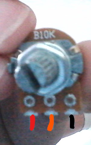
Using a small potenciometer like the b10k you can read the amount of current it lets through and use it to map and the position the servo.
To connect it follow: red to VCC, orange analog output and black ground.
Hero shoots part 2
-
The attiny44a-ssu can handle up to 4 diferent pwm signals simultaneously, however they are not meant to be different for each servo you are using, instead they are meant to be for different devices like a buzzer or speaker.
So, the second video demostrates the efficiency of a bigger servo, with metalic engines, using the same pulse.
however it's true that the black one has some knock back every time it stops and change direction, there's a not so small difference in the consumption of the servos as the maximum current of the small is 200mA while that's the minimum of the black.
Second output: Stepper motor
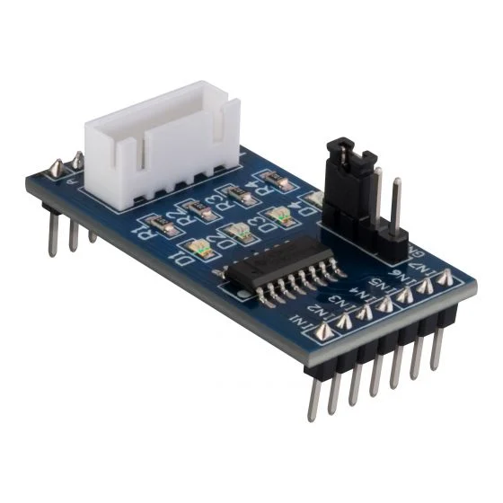
The code to handle a stepper motor in arduino using a UNL2003A driver to download: stepper.ino.
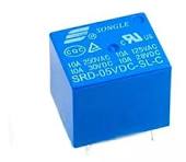
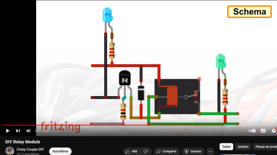
At first glance i wanted to use a dc motor controlled by a relay, but the semana santa hollidays came and i missed some key components to create a relay board, the main thing while working with a dc motor is the amount of energy they consume and a direct output from the microcontroller is not enough and a bad practice, in the video shown the minimum components needed are a relay and a diode of the voltage of your motor and a n type transistor with 5V source to open, that circuit could help to move the motor to one direction only, as a dc motor moves to the way the current is flowing through it's coils.
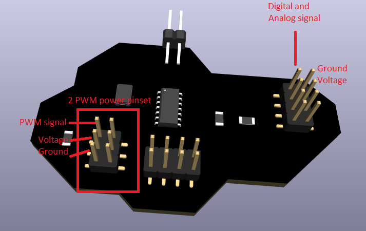
I ended up getting a stepper motor and a little board with a UNL2003A driver, the board is similar to the relay one where in the side goes the power input, but in this case, in order to control a stepper motor you will need 4 outputs as in the right diagram because of the separate coils, using an H-bridge can reduce the number of outputs in 2 but with the need of extra components.
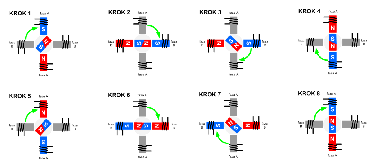
The four outputs needed
The code
//Declaration of Driver pins
byte IN1 = 0;
byte IN2 = 1;
byte IN3 = 2;
byte IN4 = 3;

//Step sequence
const int UnPaso[4] = {B1000, B0100, B0010, B0001};

//Variable indicating the number of steps
int paso = 2048; // 360° a full step

//Step counter
int Cpaso = 0;

void setup() {
  // Configure 4 Digital Pins as OUTPUTS
  for (int i = IN1; i <= IN4; i++) {
    pinMode(i, OUTPUT);
  }
}

void loop() {
  // Move forward
  for (int i = 0; i < paso; i++) {
    Cpaso++;
    if (Cpaso >= 4) {
      Cpaso = 0;
    }
    for (int j = 0; j < 4; j++) {
      digitalWrite(j + IN1, bitRead(UnPaso[Cpaso], j));
    }
    delay(5); // Adjust delay for speed
  }

  // Move backward
  for (int i = 0; i < paso; i++) {
    Cpaso--;
    if (Cpaso < 0) {
      Cpaso = 3;
    }
    for (int j = 0; j < 4; j++) {
      digitalWrite(j + IN1, bitRead(UnPaso[Cpaso], j));
    }
    delay(5); // Adjust delay for speed
  }
}
Hero shoots part 3
Third output: Oled display
The code to handle a oled in avr devices, in arduino to download: oled.ino.
LCD, OLED and AMOLED key differences:
LCD (Liquid Crystal Display):
- LCDs are passive displays that require an external light source for illumination, They typically use a backlight to provide illumination.
- LCDs generally require more power compared to OLEDs and AMOLEDs due to the need for a backlight.
OLED (Organic Light-Emitting Diode):
- OLEDs are self-emissive displays, meaning they produce their own light when an electric current passes through them, Each pixel in an OLED emits its own light
- OLED displays generally consume less power than LCDs because they don't require a backlight.
AMOLED (Active Matrix Organic Light-Emitting Diode):
- AMOLED is a type of OLED display that uses an active matrix to control each pixel individually, improving response times and power efficiency.
Costwise there is not so much difference in between the oled and the LCD the oled is around the 10$ dolars in mexico, however the amoled cost is about 3 oled displays, that's why right now we use oled, when the amoled technology price drop, will reign.
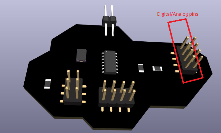
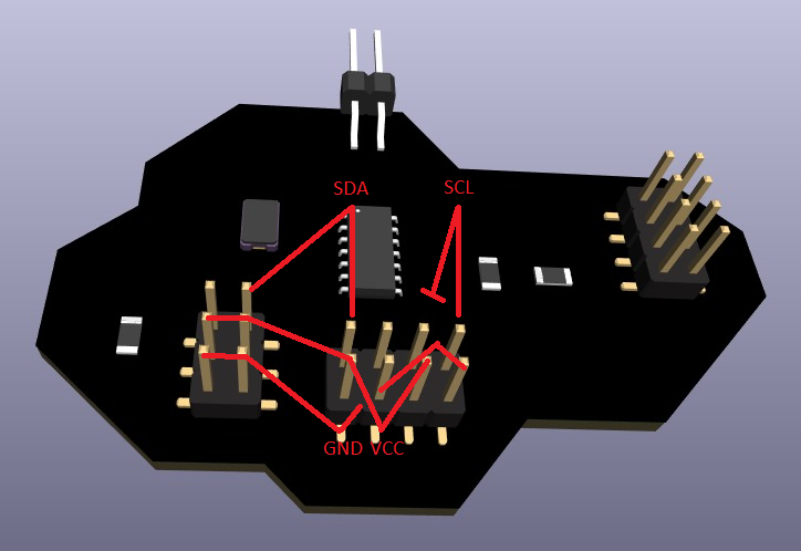
Communication required
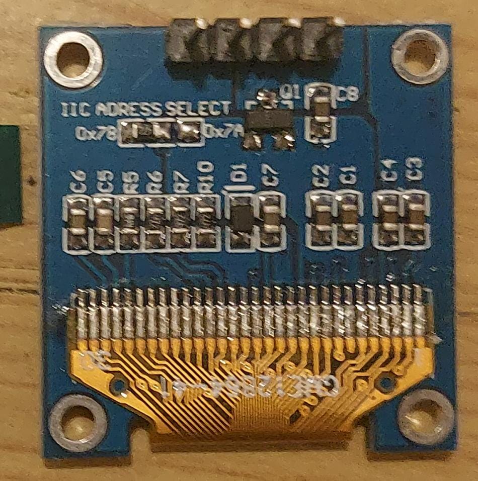
This oled display communicates via IIC(Inter-Integrated Circuit) using the SDA and SCL pins, as you can see in the second picture moving the pre-soldered resistance you can choose the adress for this Communication method, if you have more than one I2C device be sure to don't interpolate their adress and to avoid overloading the channel with useless information or routins, there's extra room in the PCB to add an extra SCL pin.
The code
#include "TinyWireM.h" //Small I2C library
#include "Tiny4kOLED.h" //Small OLED library

#define SCL 4
#define SDA 6
#define buttonPin1 8

void prepareDisplay() { //needed function to start OLED
  oled.clear();
  oled.begin();
  oled.setFont(FONT6X8); //optional: to set font size
}

void setup() {
  oled.begin(128, 64, sizeof(tiny4koled_init_128x64br), tiny4koled_init_128x64br); //size of your OLED
  oled.clear(); //clear memmory and display
  oled.on();
  prepareDisplay();
  pinMode(buttonPin1, INPUT); // Enable internal pull-up resistor
  oled.setCursor(0, 0); //specify where to start writing
  oled.print("Button pressed: ");
}

void loop(){
  delay(1000);
  if (digitalRead(buttonPin1) == HIGH){ //read button
    oled.setCursor(0, 10); //print downside the previous message
    oled.print("yes"); //pressed
    delay(1000);
  }
  else{
    oled.setCursor(0, 10); //not pressed
    oled.print("no ");
  }
}
Hero shoots part 4
Final reflection
Since I met the servo motors they seem to me a very powerful and simple tool to use as they only require a signal from the microcontroller thanks to their integrated circuit, always taking into account that their maximum rotation usually is around 180° so I think to use them in the door of my project, and several other applications, while a step-by-step engine is usually more disturbing like a dc engine, although these three engines have different specific uses to each other, I think it depends more on the creativity you have to solve your problem; on the other hand the displays have a fairly high cost-size in addition to that, they require too much memory for small and medium-sized boards, yet I think that it is always necessary to add some kind of terminal to show the information of the process.