Results: Interface and Application Programming
This week marked my first time creating an application, which proved to be an intriguing exploration of various interfaces. I utilized Processing to achieve the following results for an input:
This are the results for an output:
I am eager to continue exploring this software, as each library offers a multitude of creative possibilities that I have yet to discover.
Group Assignment: Tools Comparison
The group assignment page is here.
As a group, we worked on this comparative chart of P5.JS, Python, Processing, Fluter, Three.jsm and Inventor softwares on the following features: language, user-friendliness, operating systems, flexibility/personalization and functionality and characteristics.
What I Learned From Team Work
For the group assignment, I researched Processing and created a tutorial. This tutorial also incorporates concepts taught by our tutor, Michael Hurtado, during our class sessions.
Processing
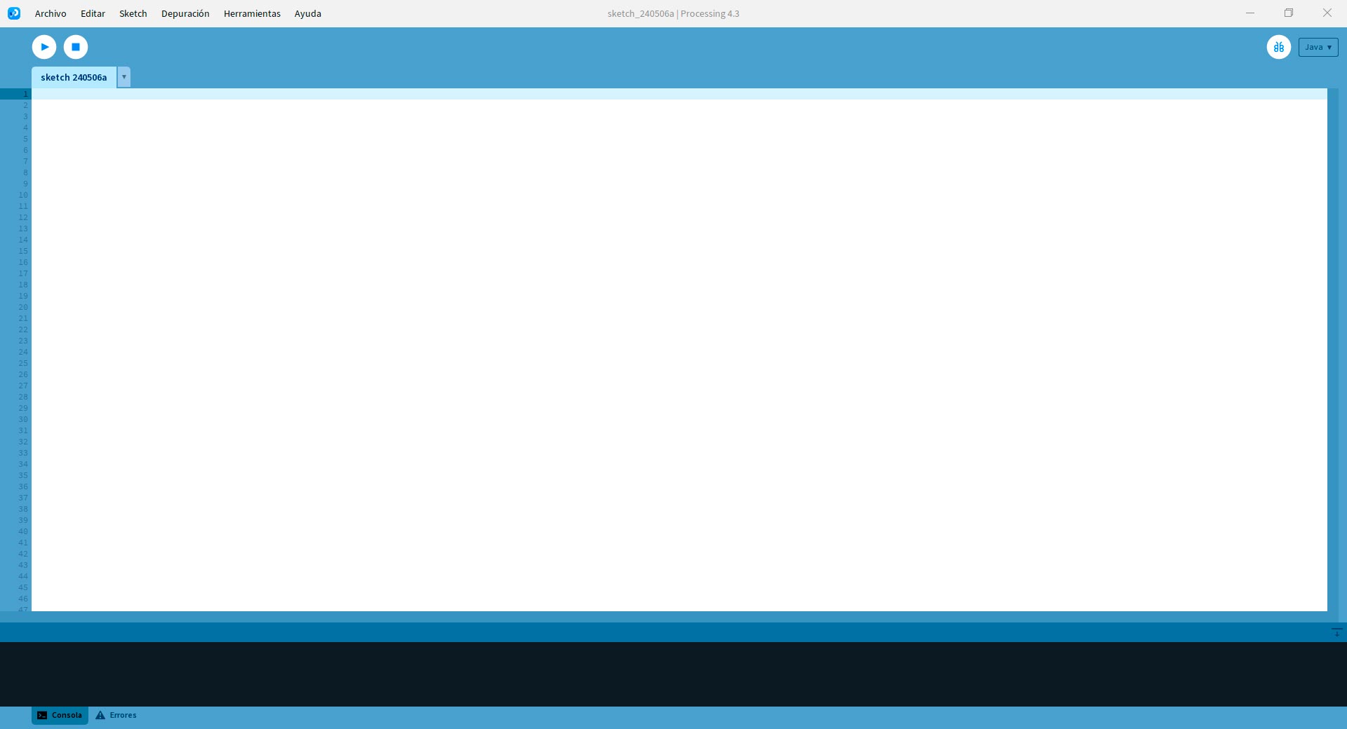
Processing is a flexible open source software sketchbook and a language for learning how to code within the context of the visual arts. It is often used for creating interactive visual applications, animations, and generative art. One of its many capabilities is its ability to communicate with external devices like Arduino IDE through serial communication.
First, you need to download and install Processing from the official website: https://processing.org/download/.
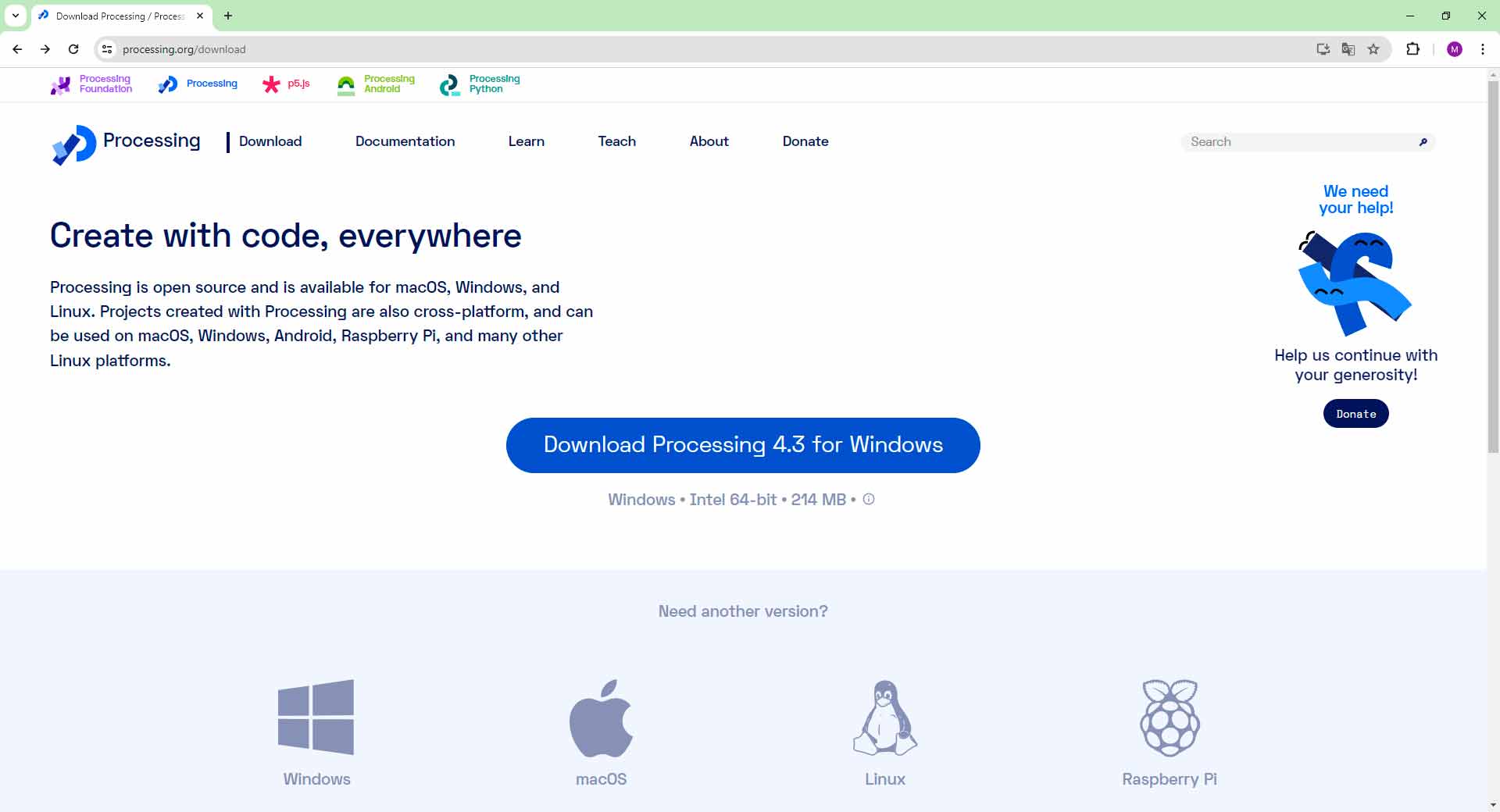
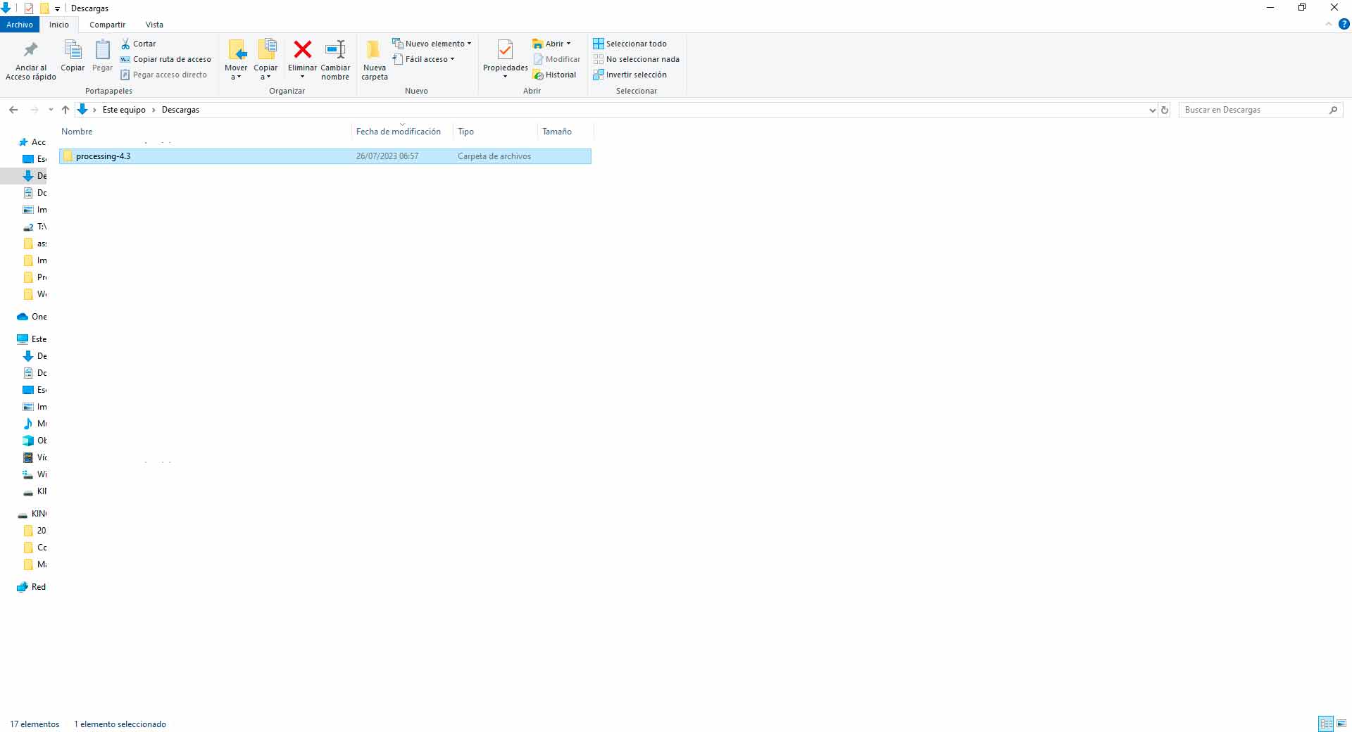
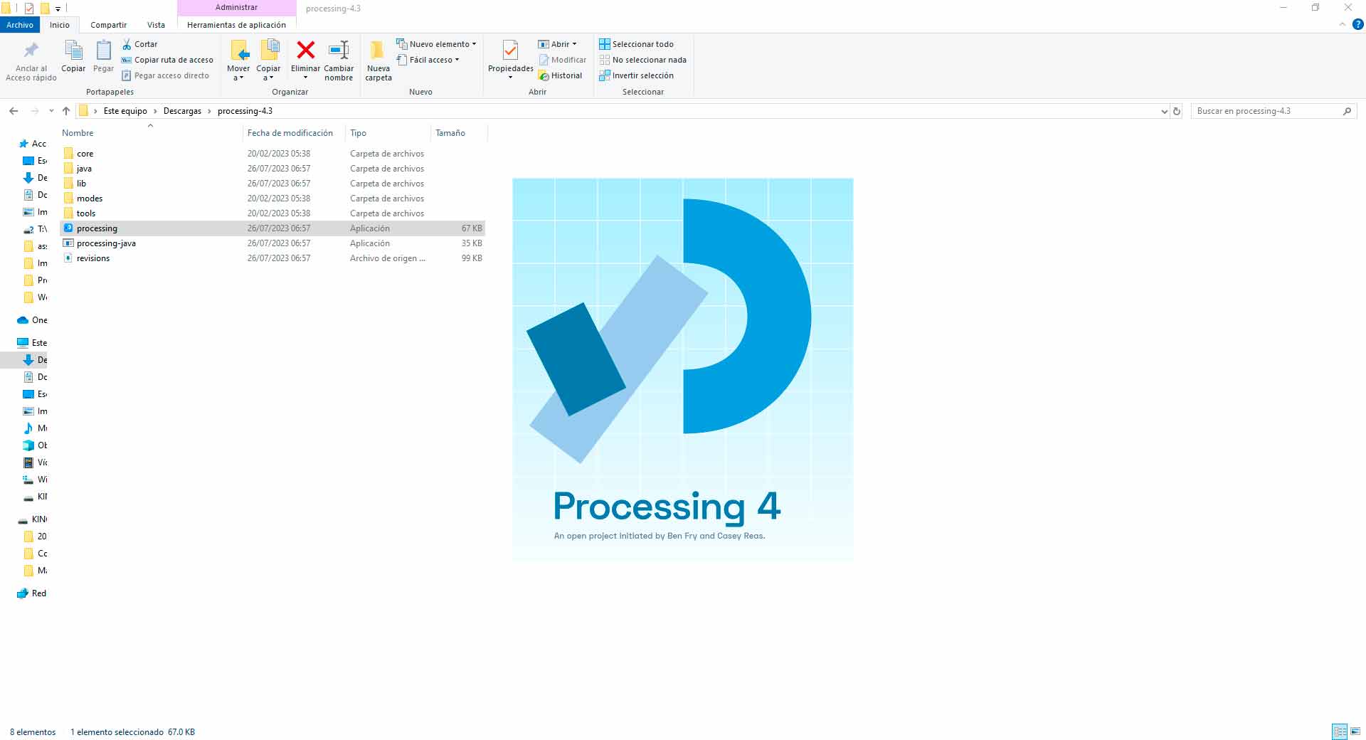
Installing Processing 4.3 in Windows
Visualization Controlled by Input's Data in Serial Port
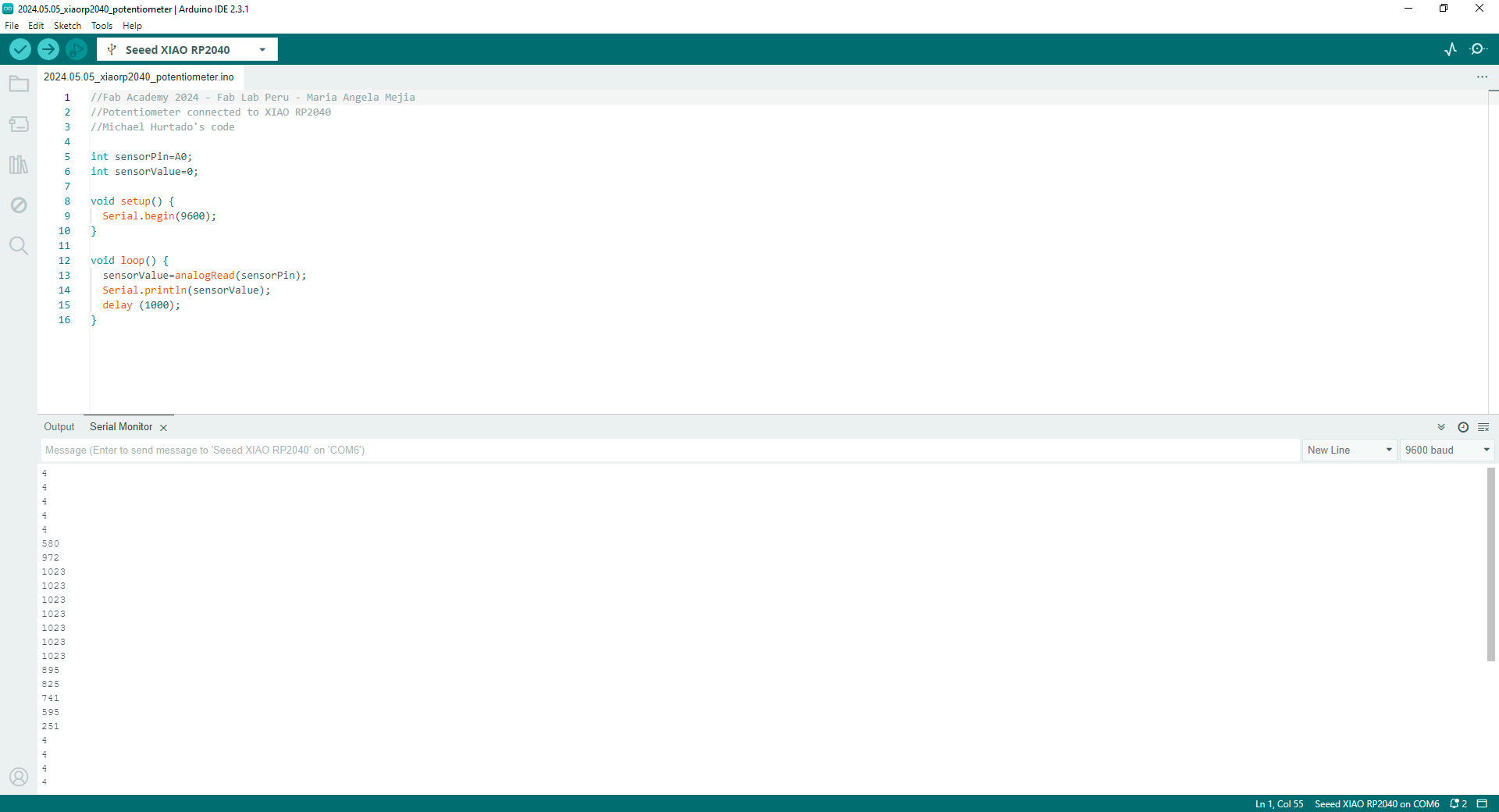
Next, you will need a device that can send data over a serial port. In this tutorial, I am utilizing the PCB I designed in week 13, connected to a XIAO RP2040. As an input I have a potentiometer. Connect your hardware to your computer via USB. Then, write the code that sends data over the serial port. I used this code in Arduino IDE:
//Fab Academy 2024 - Fab Lab Peru
//Potentiometer connected to XIAO RP2040
//Michael Hurtado's code

int sensorPin=A0;
int sensorValue=0;

void setup() {
  Serial.begin(9600);
}

void loop() {
  sensorValue=analogRead(sensorPin);
  Serial.println(sensorValue);
  delay (50);
}
Code in Arduino IDE for programming the potentiometer
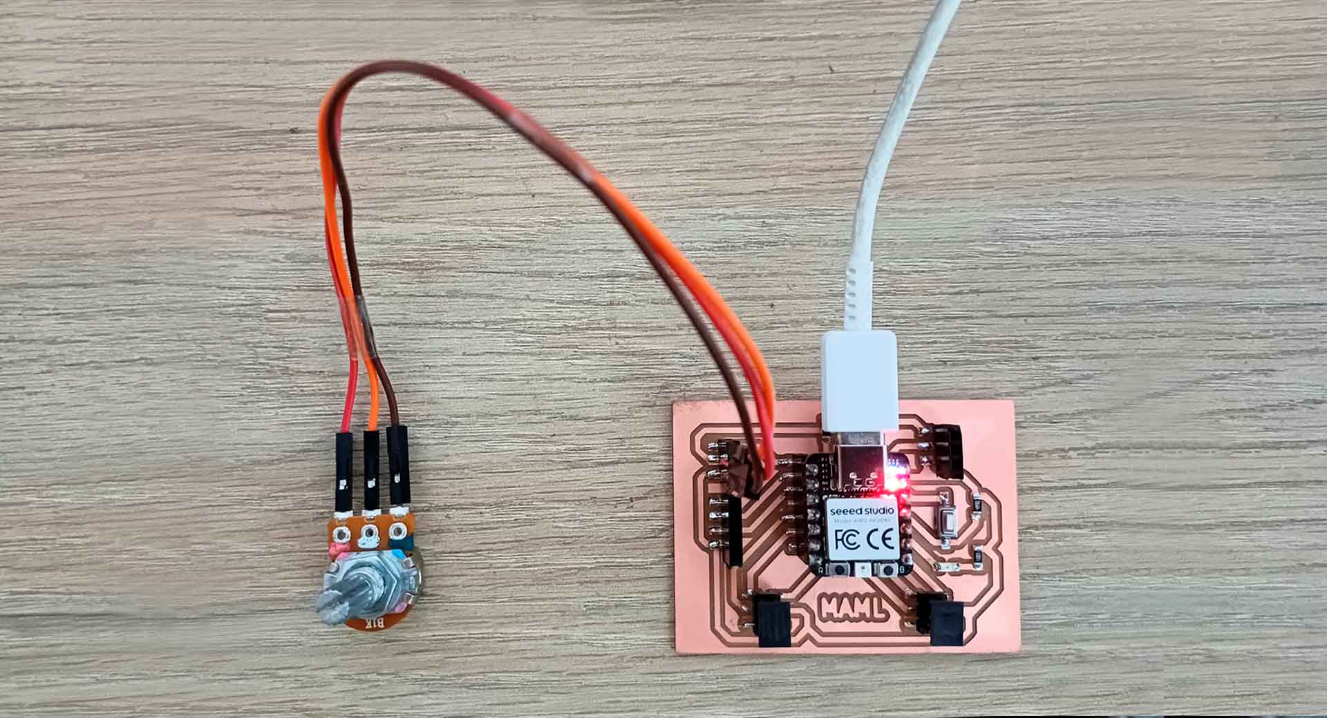
Setting up the hardware and uploading the code
Then, write the Processing code to receive and visualize the data. I used this code in Processing:
// Fab Academy 2024 - Fab Lab Peru
// Serial monitor data from a potentiometer connected to XIAO RP2040
// Michael Hurtado's code

import processing.serial.*;

Serial serialPort;		// Object for serial communication
int serialData;		// Variable to store data received via serial

float ballDiameter = 20;	// Diameter of the ball
float posX, posY;		// Position of the ball on the screen

void setup() {
  size(400, 400);	// Window size

  // Initializing the serial port
  serialPort = new Serial(this, "COM6", 9600);  // Change 9600 to the baud rate
}

void draw() {
  background(255); // White background

  // Map the values received via serial to adjust the position of the ball
  float posX = map(serialData, 0, 1023, 0, width);
  float posY = height / 2;

  // Draw the ball
  ellipse(posX, posY, ballDiameter, ballDiameter);
}

void serialEvent(Serial serialPort) {
  // Read data from the serial port and store it in the serialData variable
  String data = serialPort.readStringUntil('\n');
  if (data != null) {
	serialData = int(data.trim());
  }
}
Code in Processing
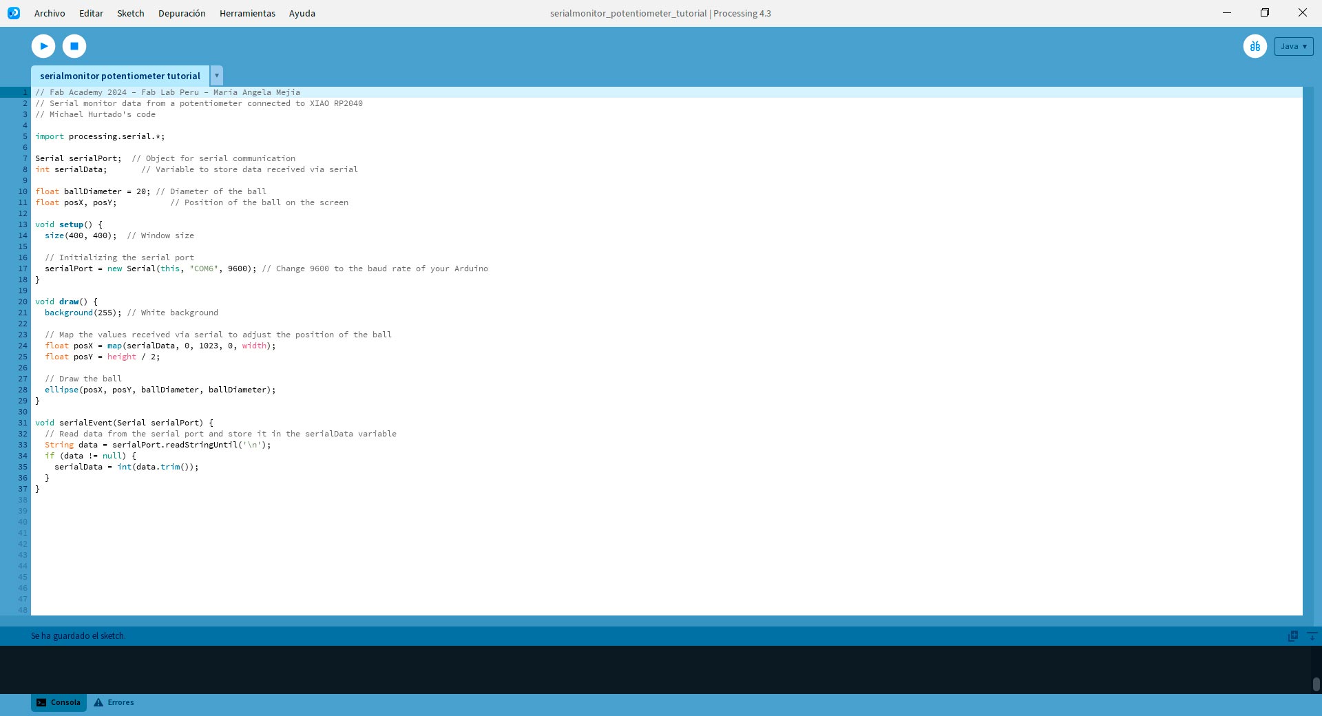
Code in Processing
Let's break down the code for understanding it:
- Importing the serial library with Import processing.serial.*; This line imports the Processing serial library, which allows communication with serial ports. You can check if the library in: Sketch - Import library. If you see the library called Serial, it means it is already installed. If not, go to Manage libraries, find the desired library, and install it.
- Declaring variables: We declare variables to handle serial communication (serialPort and serialData), as well as variables to handle the visualization (ballDiameter, posX, posY).
- Setup function: void setup() {...} This function runs once at the start of the program. It sets the window size and initializes serial communication using the Serial object. It is important to identify the correct port so that Processing obtains the data it needs for the application. In my case, I used the port "COM6".
- Draw function: void draw() {...} This function runs continuously to update the visualization. It sets the background color, maps the received serial data to adjust the position of the ball, and draws the ball on the screen.
- Serial event function: void serialEvent(Serial serialPort) {...} This function is called whenever new data is available on the serial port. It reads the incoming data and stores it in the serialData variable.
When the application is executed, the result is as follows:
Application Controlling an Output
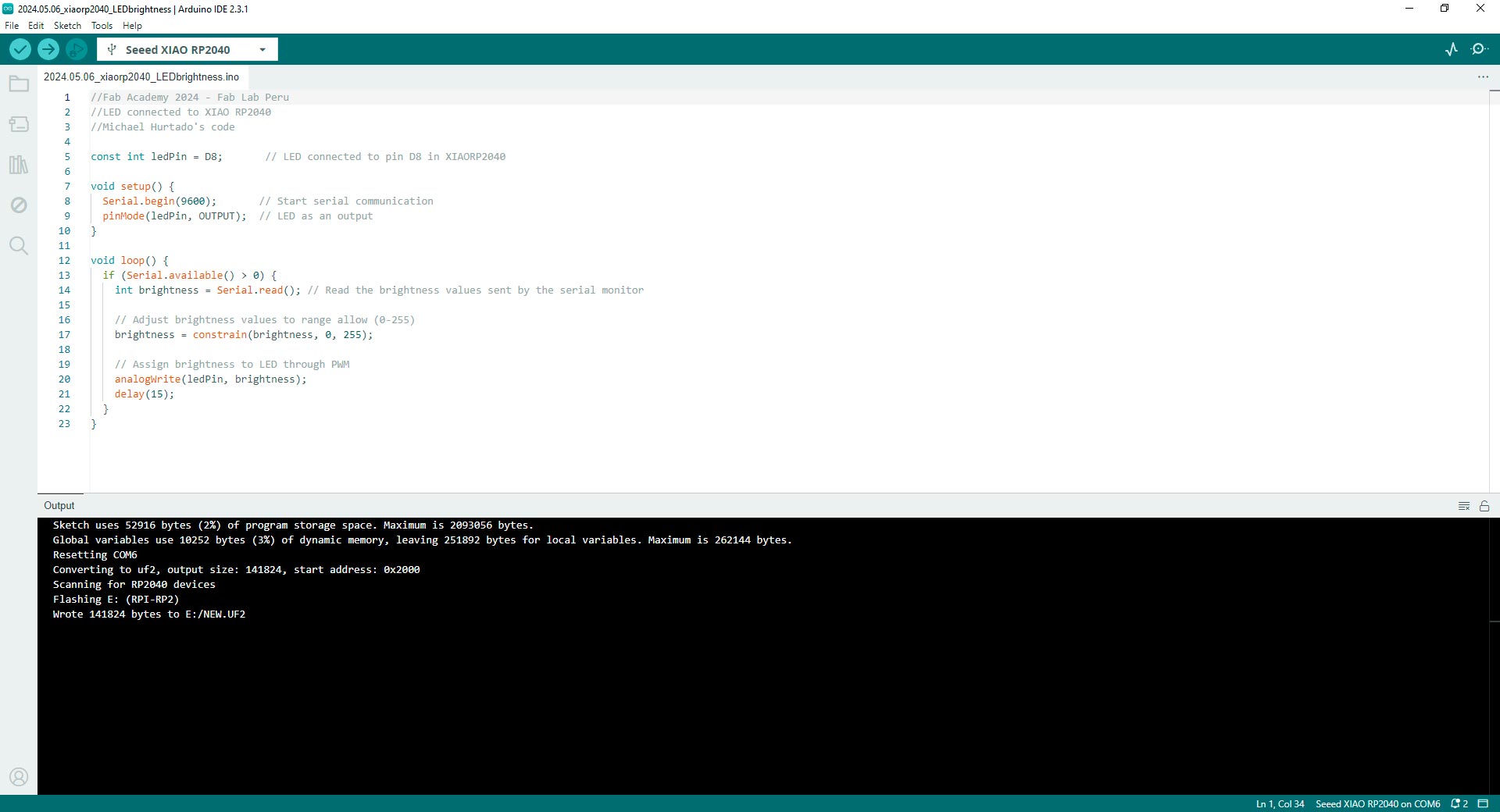
To perform the reverse action—controlling a device based on actions performed on the computer—the steps are similar, with only changes required in the code. In this case, I used the LED on my board as an output. I used this code in Arduino IDE:
//Fab Academy 2024 - Fab Lab Peru
//LED connected to XIAO RP2040
//Michael Hurtado's code

const int ledPin = D8;       // LED connected to pin D8 in XIAORP2040

void setup() {
  Serial.begin(9600);       // Start serial communication
  pinMode(ledPin, OUTPUT);  // LED as an output
}

void loop() {
  if (Serial.available() > 0) {
	int brightness = Serial.read(); // Read the brightness values sent by the serial monitor

	// Adjust brightness values to range allow (0-255)
	brightness = constrain(brightness, 0, 255);

	// Assign brightness to LED through PWM
	analogWrite(ledPin, brightness);
	delay(15);
  }
}
Code in Arduino IDE for programming the LED in PCB
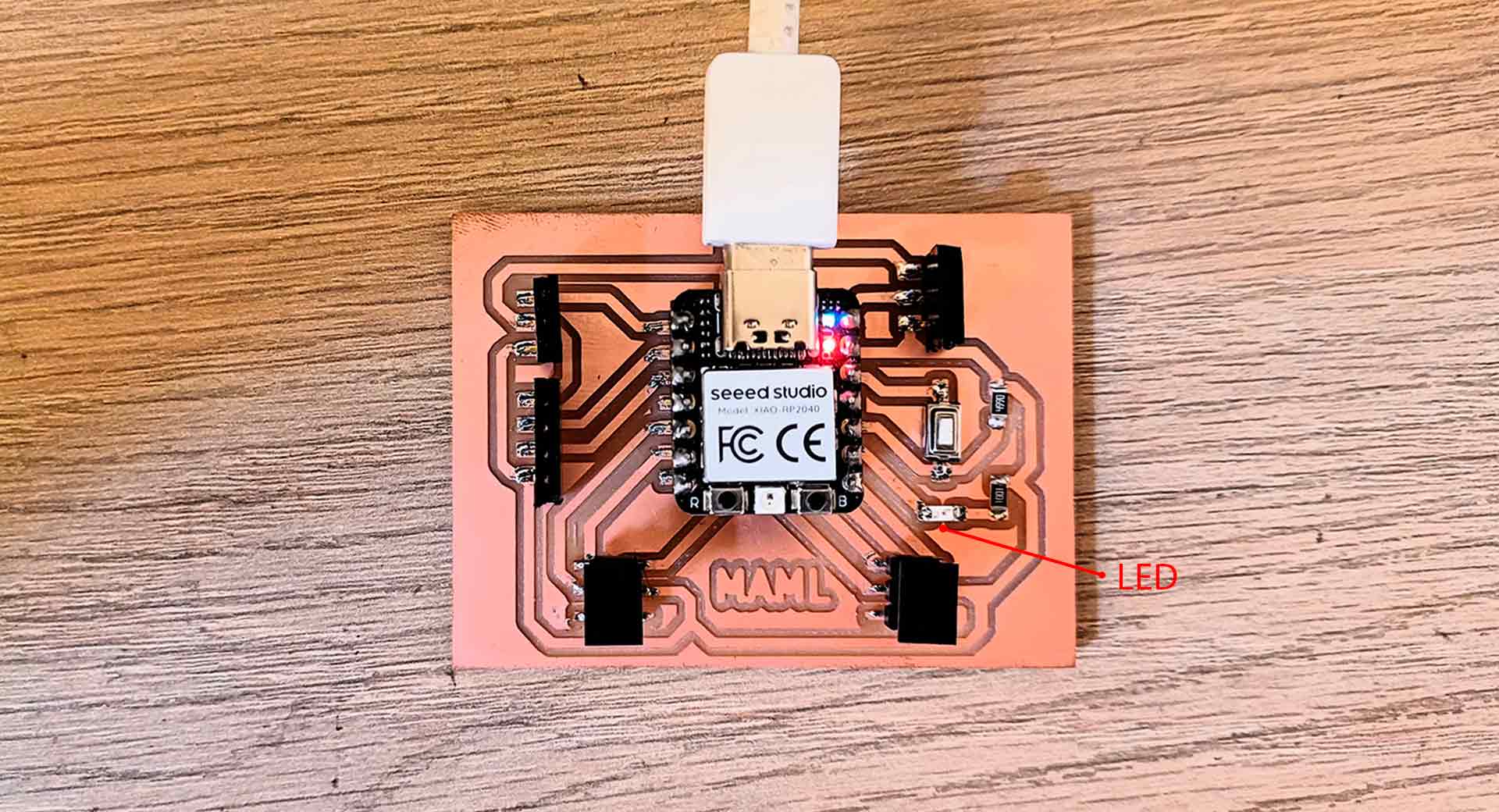
Setting up the hardware and uploading the code
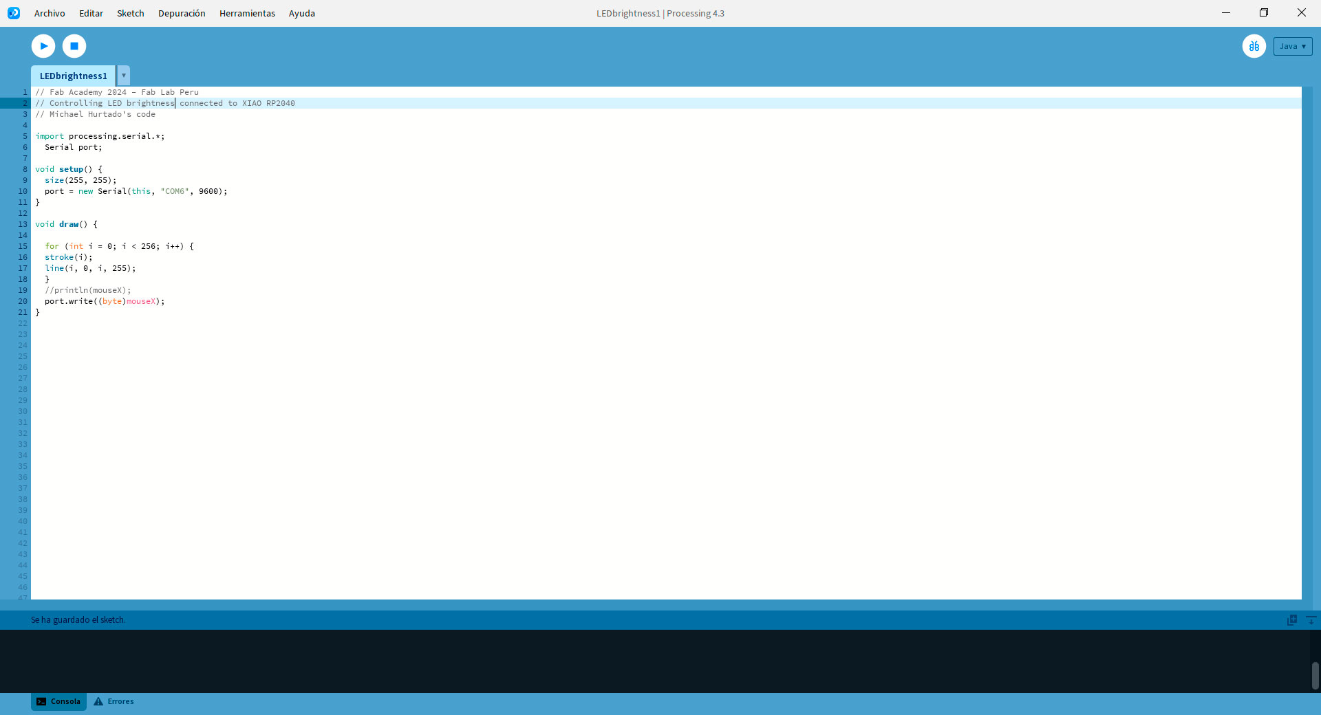
Then, write the Processing code to send and visualize the data. I used this code in Processing:
// Fab Academy 2024 - Fab Lab Peru
// Controlling LED brightness connected to XIAO RP2040
// Michael Hurtado's code

import processing.serial.*;
  Serial port;

void setup() {
  size(255, 255);
  port = new Serial(this, "COM6", 9600);
}

void draw() {

  for (int i = 0; i < 256; i++) {
  stroke(i);
  line(i, 0, i, 255);
  }
  //println(mouseX);
  port.write((byte)mouseX);
}
Code in Processing
Code in Processing
Let's break down the code for understanding it:
- Importing the serial library with Import processing.serial.*; This line imports the Processing serial library, which allows communication with serial ports.
- Setting up the serial port: Serial port; Declares a variable named port of type Serial, which will be used for serial communication.
- Setup function: void setup() {...} This function runs once at the start of the program. It sets the window size and initializes serial communication using the Serial object. It is important to identify the correct port so that Processing obtains the data it needs for the application. In my case, I used the port "COM6".
- Draw function: void draw() {...} This function runs continuously to update the visualization. It draws a gradient bar to visualize the brightness levels and sends the mouseX position (which represents the brightness level selected by the user) to the XIAO RP2040 board over the serial port.
When the application is executed, the result is as follows:
Conclusions
- Versatility in visualization: Processing offers a versatile platform for creating interactive visualizations that respond to various inputs. Whether it's data from sensors, serial communication with external devices, or user interactions, Processing provides a robust framework for visualizing this data in creative and engaging ways.
- Integration with external devices: Processing's ability to communicate with external devices via serial ports enables seamless integration with hardware such as microcontrollers like the XIAO RP2040. This capability opens up a wide range of possibilities for interactive installations, physical computing projects, and IoT (Internet of Things) applications. By combining Processing's visual capabilities with real-world inputs and outputs, creators can build interactive systems that bridge the digital and physical worlds.
- Accessibility for creativity and learning: Processing's intuitive programming environment makes it accessible for both beginners and experienced programmers to create interactive applications. Its simplified syntax and immediate feedback loop encourage experimentation and rapid prototyping, making it an ideal tool for learning programming concepts, creative coding, and digital art. Additionally, Processing's active community and extensive documentation provide ample resources for learners to explore and expand their skills in creative coding and physical computing.
Team collaboration in comparing tools like Processing for applications allows for a comprehensive understanding of their strengths and applications, facilitating informed decision-making and maximizing project potential.

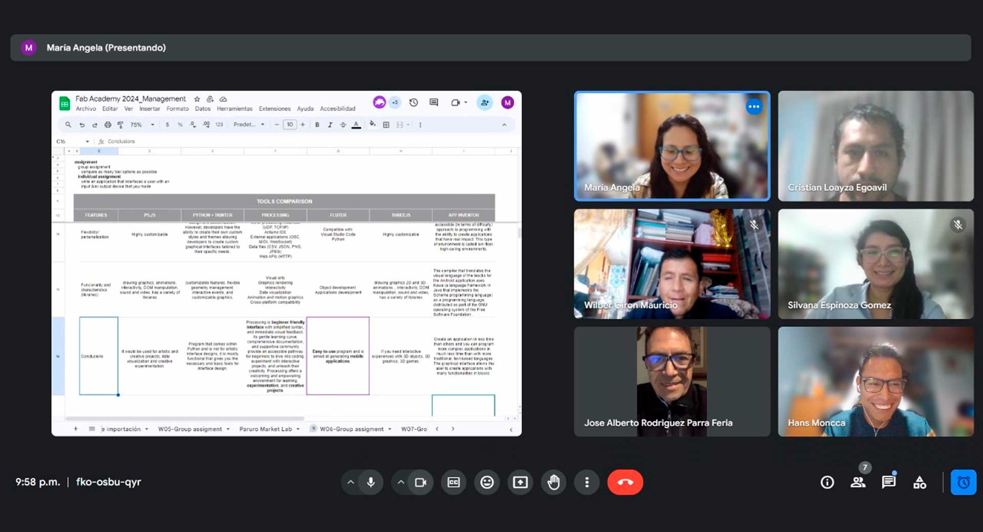
Class with Michael Hurtado and group session to compare different tools
Individual Assignment: Application
For my individual assignment, I wanted to explore more about Processing, seeking to achieve more dynamic and understandable interfaces for all audiences.
Exploring Processing with an Input
To experiment with Processing and the potentiometer that I had already worked on to make the tutorial in the group assignment, I only modified the code in this software.
I wanted to start with a playful and dynamic interface. I chose a vibrant background color, an organic and random effect for the appearance of a number of bubbles that depended on the data received through the serial port. I used the code in Processing I used in the tutorial part and chatGPT to reach the desired effect and then modified some values such as the background color and the size of the bubbles. I used the prompt: "In Processing, generate a code to visualizate bubbles based on the serial port data. When the values are low, there will be less bubbles, when they are high, there will be more bubbles". In Processing, I used the code below:
// Fab Academy 2024 - Fab Lab Peru - Maria Angela Mejia
// Serial monitor data from a potentiometer connected to XIAO RP2040

import processing.serial.*;

Serial serialPort;      // Object for serial communication
int serialData;         // Variable to store data received via serial
float noiseOffset = 0;  // Offset for Perlin noise
float waveRadius;       // Radius of the circular wave

void setup() {
  size(400, 400);  // Window size

  // Initializing the serial port
  serialPort = new Serial(this, "COM6", 9600); // Change 9600 to the baud rate of your Arduino

  waveRadius = 0; // Initialize wave radius

  // Set background color to the specified color
  background(251, 20, 85); // Background color: RGB (251, 20, 85)
}

void draw() {
  // Clear the background to remove existing bubbles
  background(251, 20, 85);

  // Update noise offset based on frame count
  noiseOffset += 0.01;

  // Update wave radius based on Perlin noise and serial data
  float noiseValue = noise(noiseOffset);
  waveRadius = map(noiseValue, 0, 1, 50, 200); // Adjust the range to control the amplitude of the wave

  // Draw bubbles with different sizes based on serial data
  for (int i = 0; i < serialData / 50; i++) {
	float x = random(width);
	float y = random(height);
	float bubbleSize = map(serialData, 0, 1023, 5, 40); // Adjust bubble size based on serial data
	fill(255); // Set bubble color to white
	ellipse(x, y, bubbleSize, bubbleSize);
  }
}

void serialEvent(Serial serialPort) {
  // Read data from the serial port and store it in the serialData variable
  String data = serialPort.readStringUntil('\n');
  if (data != null) {
	serialData = int(data.trim());
  }
}
Code in Processing
Then, I wanted my application effectively conveys emotions through the changing expression of a face, creating an engaging and interactive experience for viewers. To do this, I changed the background color, created a face using ChatGPT, and then changed the expression values to get what I wanted. I used this ChatGPT prompt: "In Processing, generate a code to visualizate an icon of a face based on the serial port data. When the values are low, the face will be sad, when the values are intermediate, the face will be neutral, and when the values are high, the face will be happy". In Processing, I used the code below:
// Fab Academy 2024 - Fab Lab Peru - Maria Angela Mejia
// Serial monitor data from a potentiometer connected to XIAO RP2040

import processing.serial.*;

Serial serialPort;  // Object for serial communication
int serialData;     // Variable to store data received via serial

void setup() {
  size(400, 400);  // Window size

  // Initializing the serial port
  serialPort = new Serial(this, "COM6", 9600); // Change 9600 to the baud rate of your Arduino
}

void draw() {
  background(255,120,0); // Set background color

  // Map the values received via serial to adjust the expression of the face
  float faceExpression = map(serialData, 0, 1023, 0, 1);

  // Draw happy, neutral, or sad face based on the value received
  if (serialData >= 0 && serialData <= 200) {
	drawHappyFace();
  } else if (serialData >= 201 && serialData <= 900) {
	drawNeutralFace();
  } else if (serialData >= 901 && serialData <= 1023) {
	drawSadFace();
  }
}

void drawHappyFace() {
  // Draw happy face
  fill(255); // Set fill color to white
  ellipse(width/2, height/2, 200, 200); // face
  fill(255); // Set fill color to white
  ellipse(width/2 - 40, height/2 - 30, 30, 30); // left eye
  ellipse(width/2 + 40, height/2 - 30, 30, 30); // right eye
  noFill();
  arc(width/2, height/2 + 30, 120, 80, 0, PI); // smile
}

void drawNeutralFace() {
  // Draw neutral face
  fill(255); // Set fill color to white
  ellipse(width/2, height/2, 200, 200); // face
  fill(255); // Set fill color to white
  ellipse(width/2 - 40, height/2 - 30, 30, 30); // left eye
  ellipse(width/2 + 40, height/2 - 30, 30, 30); // right eye
  line(width/2 - 20, height/2 + 40, width/2 + 30, height/2 + 30); // neutral mouth
}

void drawSadFace() {
  // Draw sad face
  fill(255); // Set fill color to white
  ellipse(width/2, height/2, 200, 200); // face
  fill(255); // Set fill color to white
  ellipse(width/2 - 40, height/2 - 30, 30, 30); // left eye
  ellipse(width/2 + 40, height/2 - 30, 30, 30); // right eye
  noFill();
  arc(width/2, height/2 + 70, 120, 80, PI, TWO_PI); // frown
}

void serialEvent(Serial serialPort) {
  // Read data from the serial port and store it in the serialData variable
  String data = serialPort.readStringUntil('\n');
  if (data != null) {
	serialData = int(data.trim());
  }
}
Code in Processing
Exploring Processing with an Output
To experiment with Processing and the LED that I had already worked on to make the tutorial in the group assignment, I only modified the code in this software.
I wanted to start with an interface where it could be easy to control and know the intensity value of the LED brightness. To do this, I used a numbered knob and text indicating the value. To achieve this, I had to install the controlP5 library. I used the code base worked on in Michael Hurtado's class (the one I used previously in the tutorial) and the following prompt in ChatGPT:"In Processing, generate a code to control the brightness of a LED with a knob with numbers and a text that indicates the value". Then, I change the position of the knob and text. In Processing, I used the code below:
// Fab Academy 2024 - Fab Lab Peru - Maria Angela Mejia
// Code to control LED brightness connected to XIAO RP2040

import processing.serial.*;
import controlP5.*;

Serial port;    // Processing serial object
ControlP5 cp5;  // ControlP5 object for creating the slider
Knob knob;      // Knob object to control the sent value by serial port

void setup() {
  size(400, 400);

  // Start the serial communication and ControlP5 object
  port = new Serial(this, "COM6", 9600);
  cp5 = new ControlP5(this);

  // Generate the knob with circular indicator
  knob = cp5.addKnob("knobValue")
	.setPosition(150, 150)
	.setRange(0, 255)    // Knob value range
	.setValue(0)       // Knob initial value
	.setRadius(50)       // Knob radius
	.setNumberOfTickMarks(10) // Number of tick marks around the knob
	.setDragDirection(Knob.HORIZONTAL); // Set the drag direction
}

void draw() {
  background(255);
  // Draw the actual value of knob
  fill(0);
  textSize(16);
  String displayText = "Knob value: " + int(knob.getValue());
  float textWidth = textWidth(displayText);
  text(displayText, (width - textWidth) / 2, 60);
}

// Function executing when the value of the knob changes
void knobValue(float value) {
  // Send the knob value to serial port
  port.write(int(value));
}
Code in Processing
Next, I explored making an array of knobs so that the previously used value could be displayed. To do this, I used the following prompt in ChatGPT: "Based on the previous code, create an array of knobs.". In Processing, I used the code below:
// Fab Academy 2024 - Fab Lab Peru - Maria Angela Mejia
// Code to control LED brightness connected to XIAO RP2040

import processing.serial.*;
import controlP5.*;

Serial port;    // Processing serial object
ControlP5 cp5;  // ControlP5 object for creating the knobs
int numRows = 4;  // Number of rows in the matrix
int numCols = 4;  // Number of columns in the matrix
Knob[][] knobs; // 2D array to store knobs

void setup() {
  size(400, 400);

  // Start the serial communication and ControlP5 object
  port = new Serial(this, "COM6", 9600);
  cp5 = new ControlP5(this);

  // Initialize the 2D array of knobs
  knobs = new Knob[numRows][numCols];

  // Generate knobs for each cell in the matrix
  int knobWidth = 50;  // Width of each knob
  int knobHeight = 50; // Height of each knob
  int spacing = 10;    // Spacing between knobs
  for (int i = 0; i < numRows; i++) {
    for (int j = 0; j < numCols; j++) {
      knobs[i][j] = cp5.addKnob("knobValue_" + i + "_" + j)
        .setPosition(50 + j * (knobWidth + spacing), 100 + i * (knobHeight + spacing))
        .setRange(0, 255)    // Knob value range
        .setValue(0)       // Knob initial value
        .setSize(knobWidth, knobHeight)
        .setNumberOfTickMarks(10) // Number of tick marks around the knob
        .setDragDirection(Knob.HORIZONTAL); // Set the drag direction
    }
  }
}

void draw() {
  background(255);
}

// Function executing when the value of a knob changes
void controlEvent(ControlEvent event) {
  for (int i = 0; i < numRows; i++) {
    for (int j = 0; j < numCols; j++) {
      String knobName = "knobValue_" + i + "_" + j;
      if (event.isFrom(cp5.getController(knobName))) {
        int value = int(event.getController().getValue());
        // Send the knob value to serial port
          port.write(value);
        }
    }
  }
}
Code in Processing
Thanks to the assignment this week, allowed me to explore for the first time various interfaces to improve the user experience of actions generated with inputs and outputs.
Conclusions
- Visualization plays a crucial role in enhancing user experience by providing intuitive and engaging interfaces that communicate information effectively. In interactive applications developed with Processing, visual elements serve as the primary means of interaction, guiding users through the experience and conveying complex data in a digestible format.
- Processing provides a platform for creative expression by allowing artists, designers, and programmers to explore interactive visualizations and generative art. It encourages experimentation with inputs such as sensor data, user interactions, or external APIs to create unique and engaging visual experiences.
- Processing's real-time capabilities enable dynamic interaction between users and visualizations. This real-time feedback fosters engagement and allows for interactive storytelling, where the visual output responds to user inputs or changes in the environment.
- Processing's extensive library ecosystem provides access to a wide range of tools and functionalities, allowing users to leverage existing code and resources to enhance their projects. However, it's important to review the documentation and source code of libraries carefully to understand how they work and ensure compatibility with your project's requirements.
- Beginners can leverage ChatGPT for guidance, inspiration, and troubleshooting while exploring Processing. ChatGPT can provide helpful insights, suggest optimizations, and offer alternative approaches to coding challenges. However, beginners should exercise caution and critically evaluate the suggestions provided by ChatGPT, as they may require further review and validation, especially in complex coding scenarios.
- To finish this task I thank my fellow students and tutors, especially Roberto Delgado and Michael Hurtado for the guidance in this process.