Results: Networking and Communications
During the Fab Academy I have managed to program the XIAO RP2040 in previous weeks. The difference with the XIAO ESP32C3 is that it has WiFi/Bluetooth, so it is possible to generate codes that allow communication and be able to perform tasks from other devices such as cell phones.
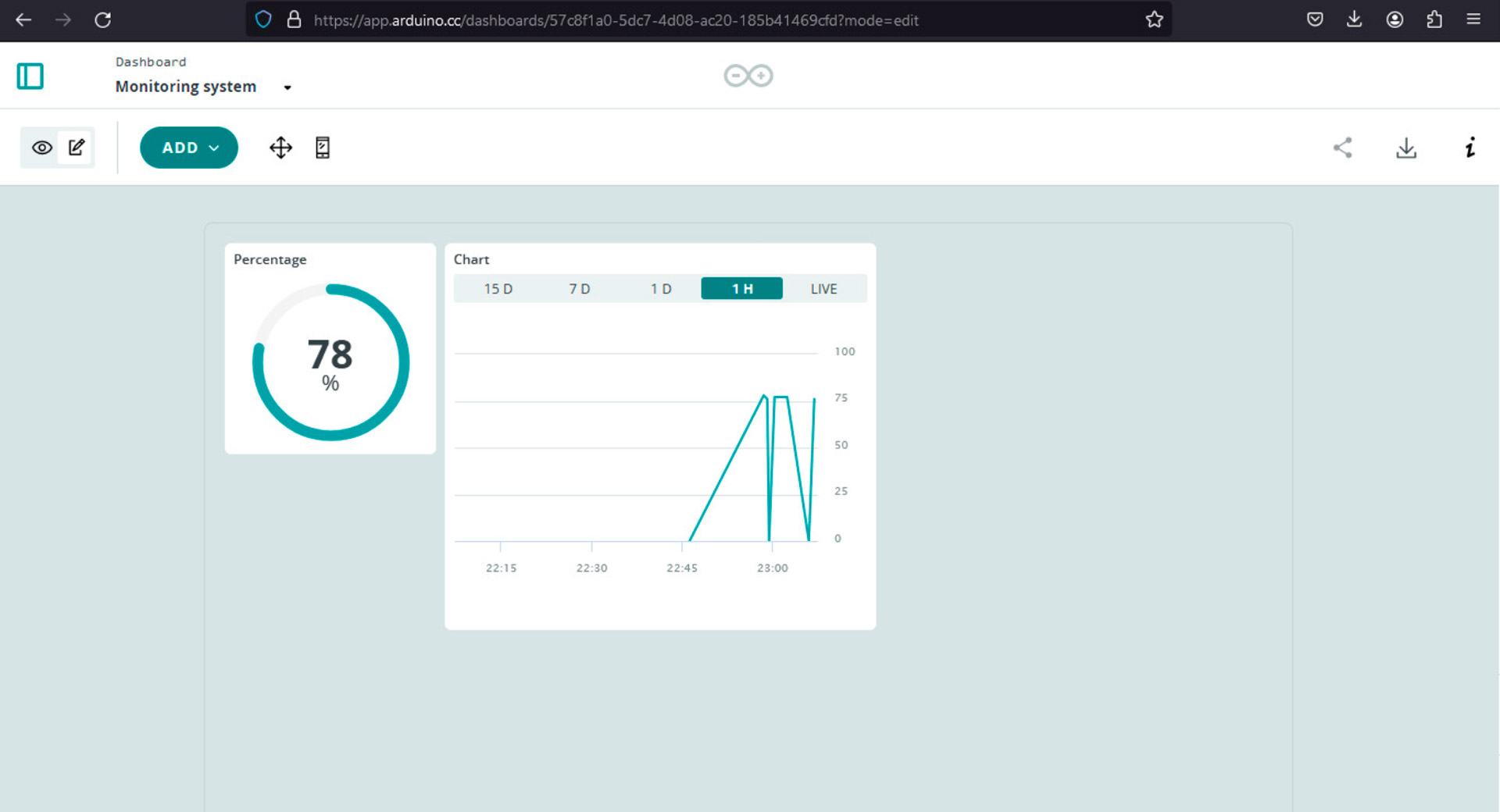
Dashboard showing the data from soil moisture sensor
This assignment was especially challenging, because although I already understand the programming, factors such as the Wi-Fi signal made this activity more complex.
Individual Assignment: Connect Nodes
Seeed Studio XIAO ESP32C3
This week I worked with Seeed Studio XIAO ESP32C3. It is is an IoT mini development board based on the Espressif ESP32-C3 WiFi/Bluetooth dual-mode chip. ESP32-C3 is a 32-bit RISC-V CPU, which includes an FPU (Floating Point Unit) for 32-bit single-precision arithmetic with powerful computing power. It has excellent radio frequency performance, supporting IEEE 802.11 b/g/n WiFi, and Bluetooth 5 (LE) protocols. This board comes included with an external antenna to increase the signal strength for your wireless applications. It also has a small and exquisite form-factor combined with a single-sided surface-mountable design. It is equipped with rich interfaces and has 11 digital I/O that can be used as PWM pins and 4 analog I/O that can be used as ADC pins. It supports four serial interfaces such as UART, I2C and SPI. There is also a small reset button and a bootloader mode button on the board.
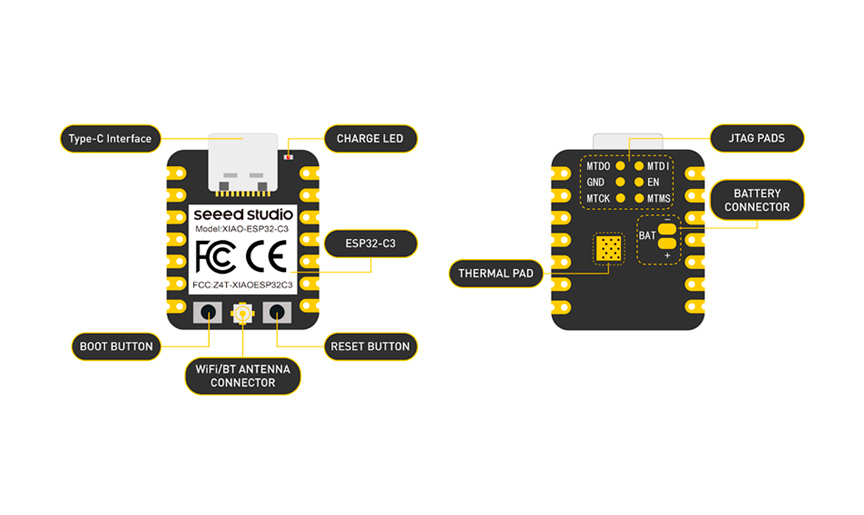
Seeed Studio XIAO ESP32C3
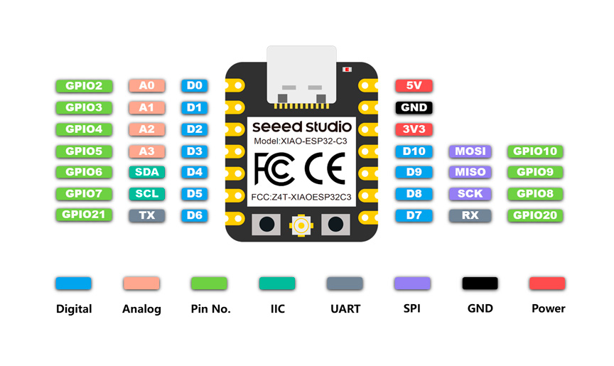
XIAO ESP32C3 pinout
Before starting this week's task, I started by programming some basic actions in Arduino IDE. To do this, I reviewed this guide. First, I added ESP32 board package to Arduino IDE in File > Preferences, and filled Additional Boards Manager URLs with this URL: https://raw.githubusercontent.com/espressif/arduino-esp32/gh-pages/package_esp32_index.json. Then I navigated to Tools > Board > Boards Manager, typed the keyword "esp32" in the search box, selected the latest version of esp32, and installed it.
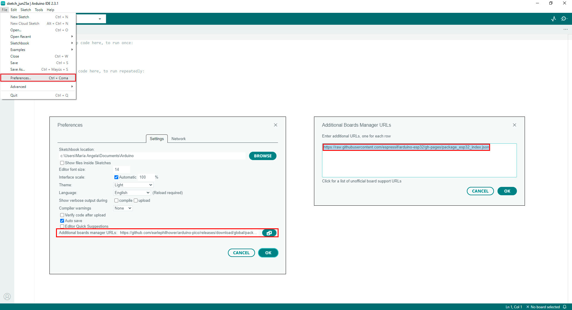
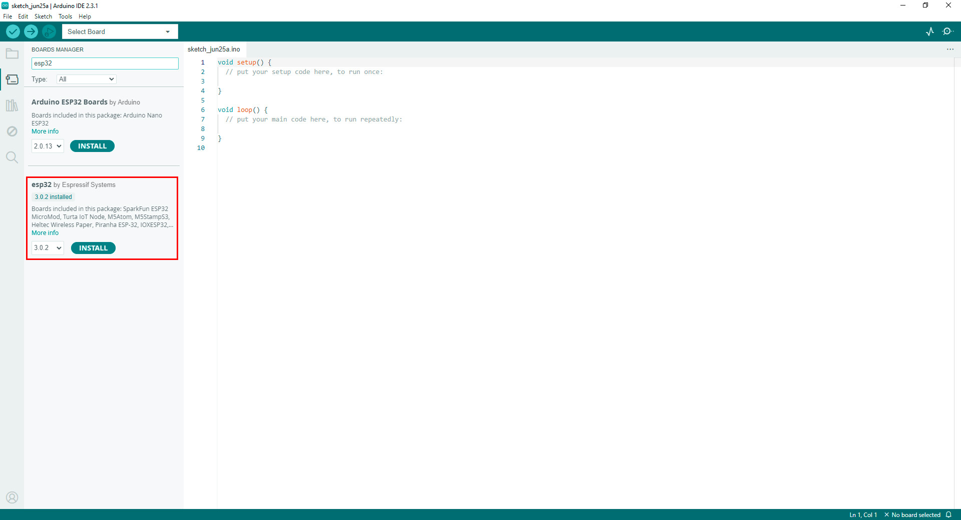
Adding ESP32 package in Arduino IDE
Then, I navigated to Tools > Board > ESP32 and select XIAO_ESP32C3. For selecting the port, I navigated to Tools > Port and selected COM9 (COM1 and COM2 are usually reserved for hardware serial ports).
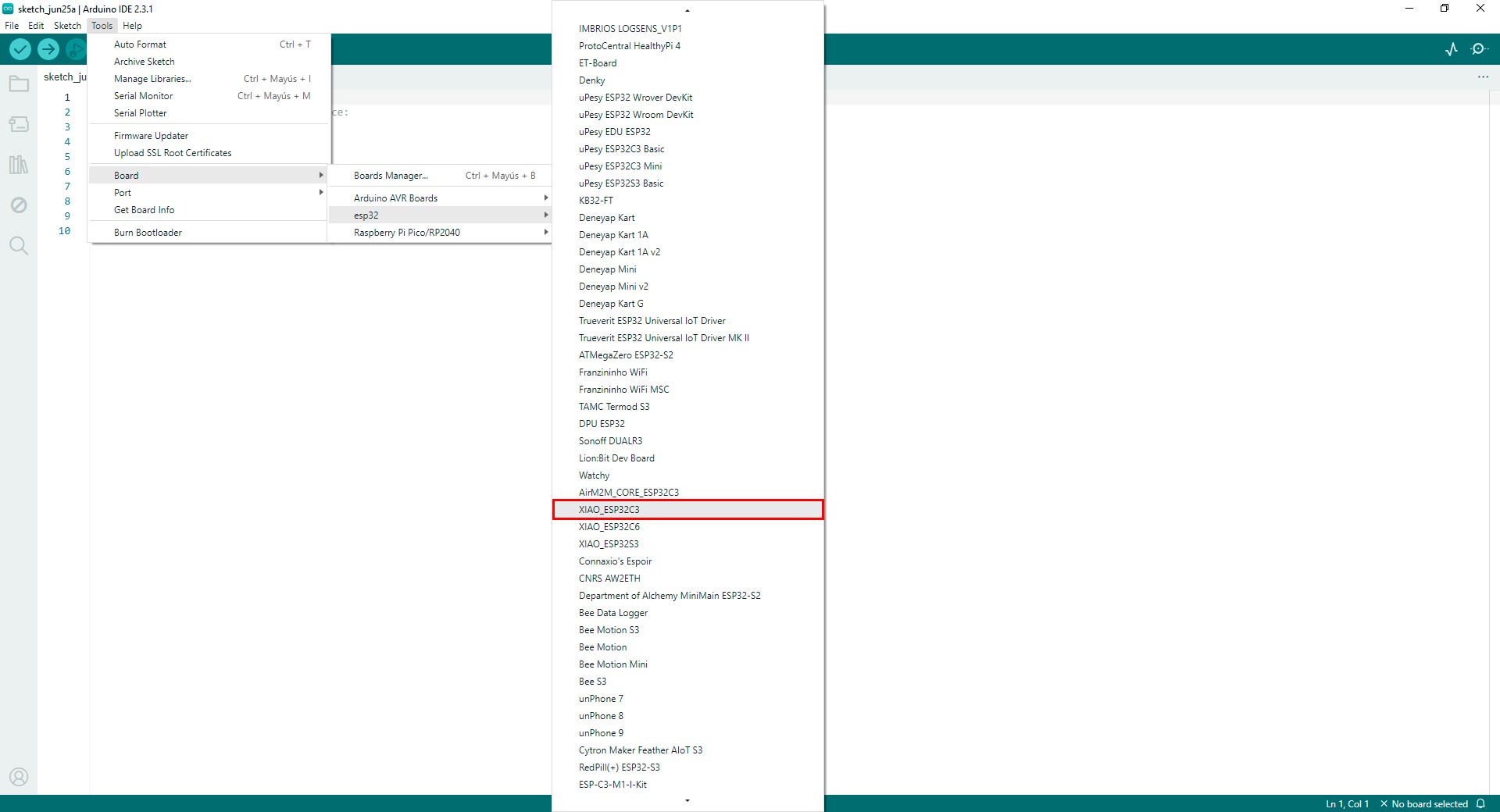
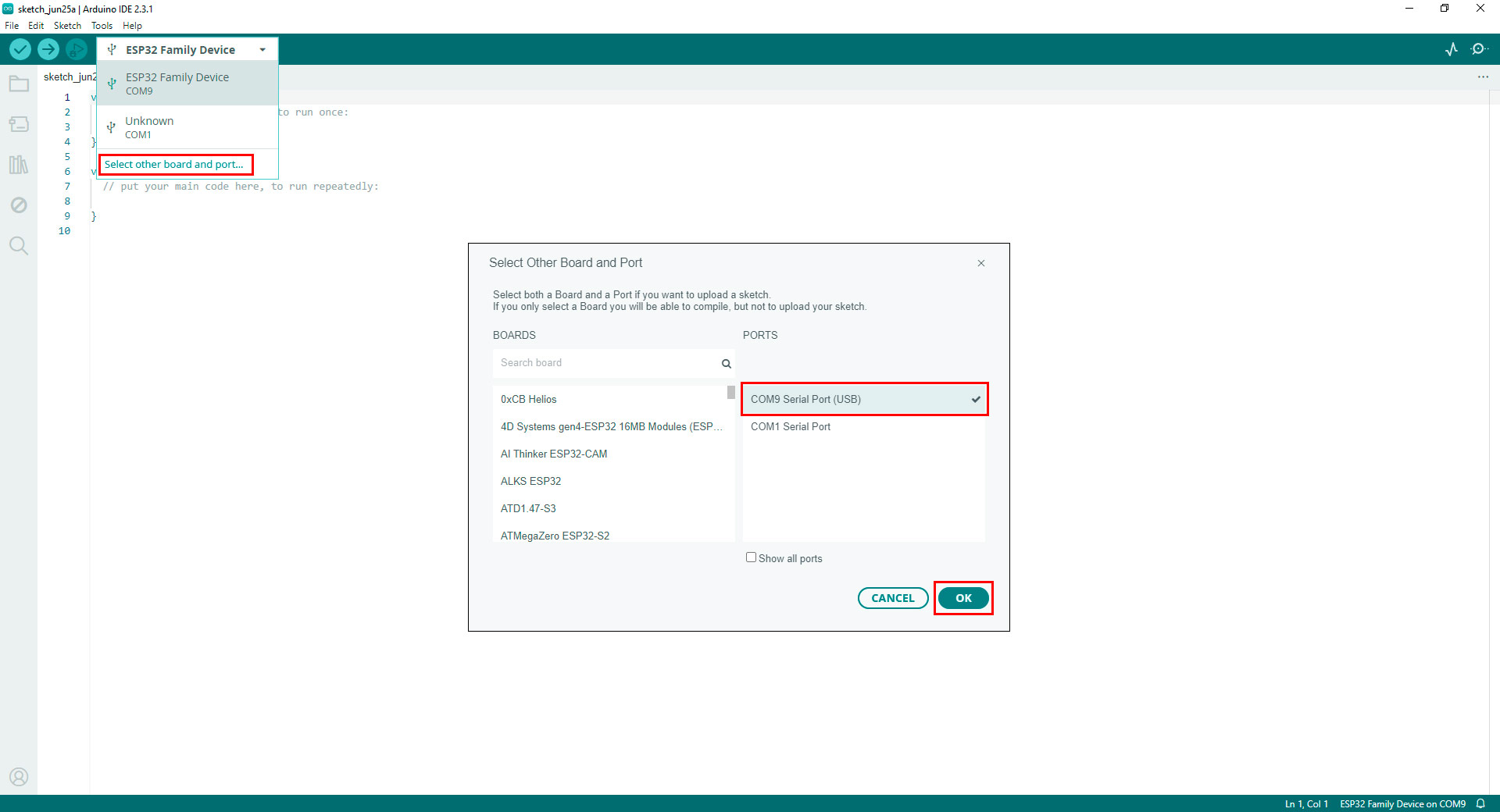
Configurating the board and port in Arduino IDE
For exploring coding for XIAO ESP32C3, I started connecting a LED and programmed it to blink with a 1-second delay between each blink. I used this code in Arduino IDE that I found in this guide:
// define led according to pin diagram
int led = D10;

void setup() {
  // initialize digital pin led as an output
  pinMode(led, OUTPUT);
}

void loop() {
  digitalWrite(led, HIGH);   // turn the LED on
  delay(1000);               // wait for a second
  digitalWrite(led, LOW);    // turn the LED off
  delay(1000);               // wait for a second
}
Code in Arduino IDE for programming a LED
Next, I tested the wifi connection. While trying to upload the code, this error appeared: exit status 2. For solving it, I disconnected the C-port wire, pushed down the boot button and while it was still pushed, I connected the C-port to the computer. Then, I released the boot button and uploaded the code. After uploading it, nothing happened. So, I disconneted the C-port once more and reconnected it. Then, the code worked. I pressed the boot button I used this code in Arduino IDE that I found in this guide:
#includeconst char* ssid = "Mari-Galaxy-A34-5G"; const char* password = "network password"; void setup() { Serial.begin(115200); delay(10); // We start by connecting to a WiFi network Serial.println(); Serial.println(); Serial.print("Connecting to "); Serial.println(ssid); WiFi.begin(ssid, password); while (WiFi.status() != WL_CONNECTED) { delay(500); Serial.print("."); } Serial.println(""); Serial.println("WiFi connected"); Serial.println("IP address: "); Serial.println(WiFi.localIP()); } void loop() { }
Code in Arduino IDE for programming a LED
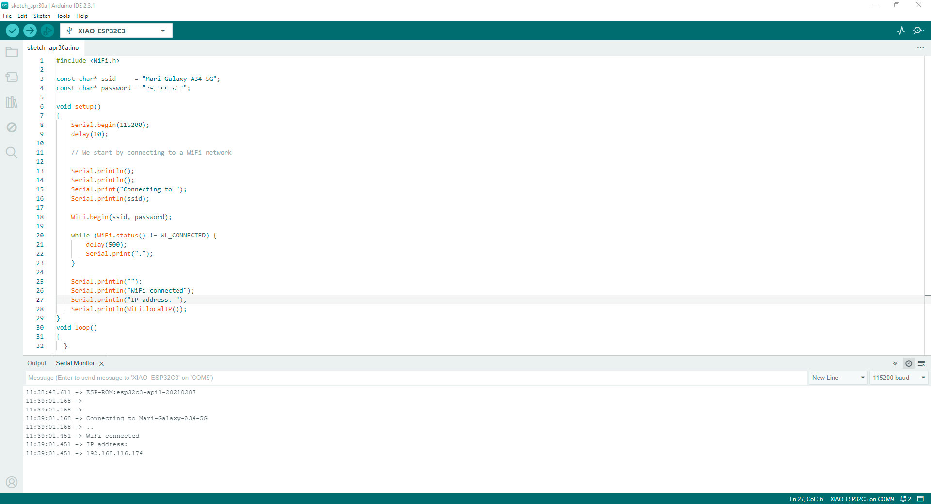
Connecting XIAO ESP32C3 to a WiFi network in Arduino IDE
Since the codes worked, I tested the code I will used first in the breadboard for then test it in my Fab&Plant PCB for debugging issues. The code I used in Arduino IDE was this:
//Fab Academy 2024 - Fab Lab Peru - Maria Angela Mejia
//Soil moisture sensor (analog pin) and RGB strip (digital pin) code for XIAO ESP32C3 in Fab&Plant PCB

int _moisture, sensor_analog;
const int sensor_pin = A0;				// Soil moisture sensor A0 pin
const int RGB_strip = 10;				// Digital pin D10 for the RGB strip

void setup(void) {
  Serial.begin(9600);					// Set the baudrate to 9600
  pinMode(RGB_strip, OUTPUT);			// Set RGB_strip as an output
}

void loop(void) {
  sensor_analog = analogRead(sensor_pin);
  _moisture = (100 - ((sensor_analog / 4095.00) * 100));
  Serial.print("Moisture = ");
  Serial.print(_moisture);          	// Print humidity percentage on the serial monitor
  Serial.println("%");

  if (_moisture >= 40) {            // Check if humidity is 40% or above
	digitalWrite(RGB_strip, LOW);   // Turn on the RGB strip
  } else {
	digitalWrite(RGB_strip, HIGH);  // Turn off the RGB strip
  }

  delay(5000);                      // Wait for 5 seconds
}
Code in Arduino IDE for humidity sensor and RGB strip
After getting familiar with this microcontroller, I started programming it in Arduino IoT Cloud.
Soldering XIAO ESP32C3 to Fab&Plant PCB
Since I needed to generate a file quickly before going to the Fab Lab to use the router, I worked on an initial design of the name of my final project. At that time, I still wasn't clear on how I could use it, but this process helped me understand the design of a mold that I later used to design the molds for the icons of my final project.
Therefore, I made this initial design in Onshape, a software that I already master. I used the line, offset, extrude, and text tools to design this mold.
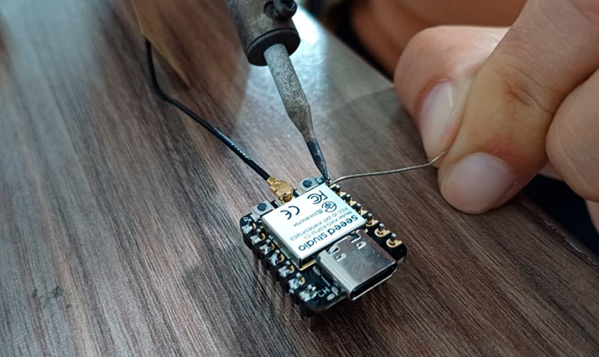
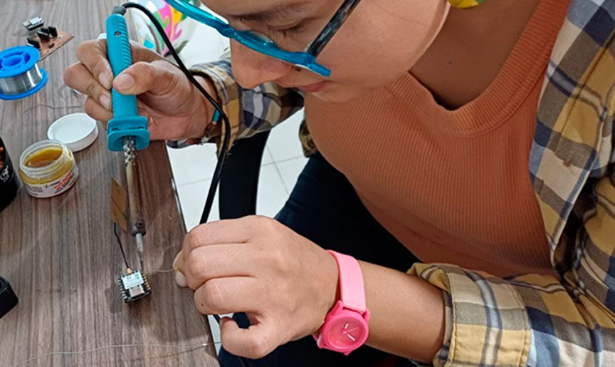
Soldering XIAO ESP32C3
Here is the result of that design:
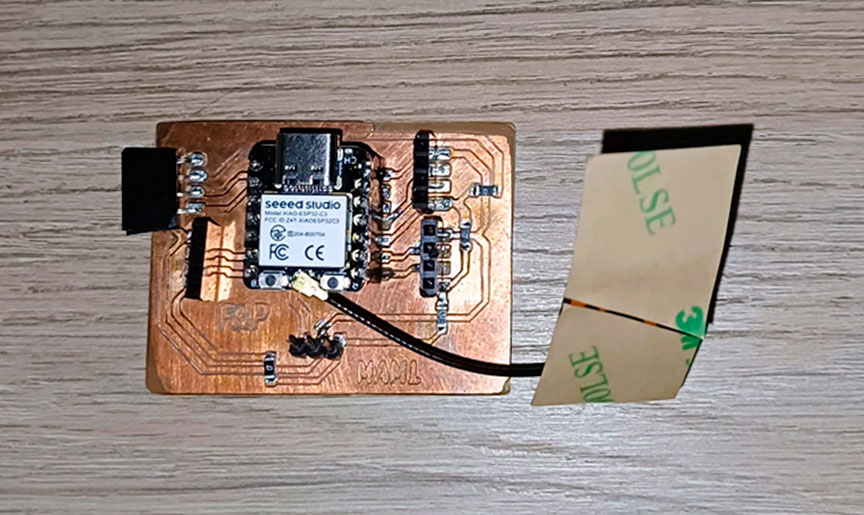
Fab&Plant PCB with XIAO ESP32C3
Connect Nodes with Arduino IoT Cloud
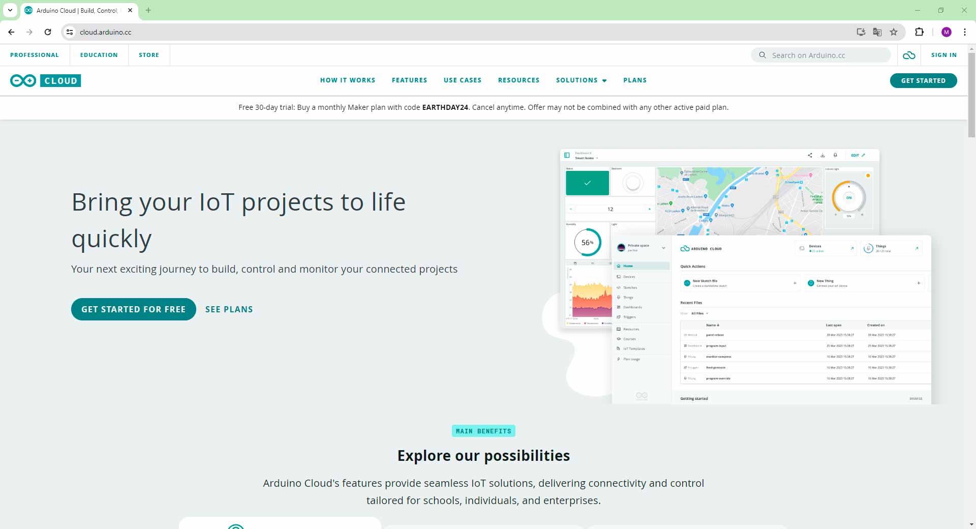
Arduino IoT Cloud is a platform that enables users to build connected projects and IoT applications with ease. It allows for the integration of various devices -including the Seeed XIAO ESP32C3- with the cloud, enabling remote monitoring and control of sensors and actuators. In this project, I used the Arduino IoT Cloud platform to display sensor readings. The network communication is facilitated through HTTP requests, which involves generating an IP address and making HTTP requests to send data to the cloud. The microcontroller will obtain an IP address when it connects to the Wi-Fi network, which is used to identify the device on the network. To send data to the Arduino IoT Cloud, HTTP requests are made by specifying the URL of the Arduino IoT Cloud server along with the necessary parameters and data payload.
Arduino IoT Cloud
First, I logged in to the Arduino IoT Cloud platform.
Arduino IoT Cloud platform
Before using the Arduino IoT Cloud, I needed to install the Arduino Create Agent plugin. This plugin allowed my browser to communicate with my devices.
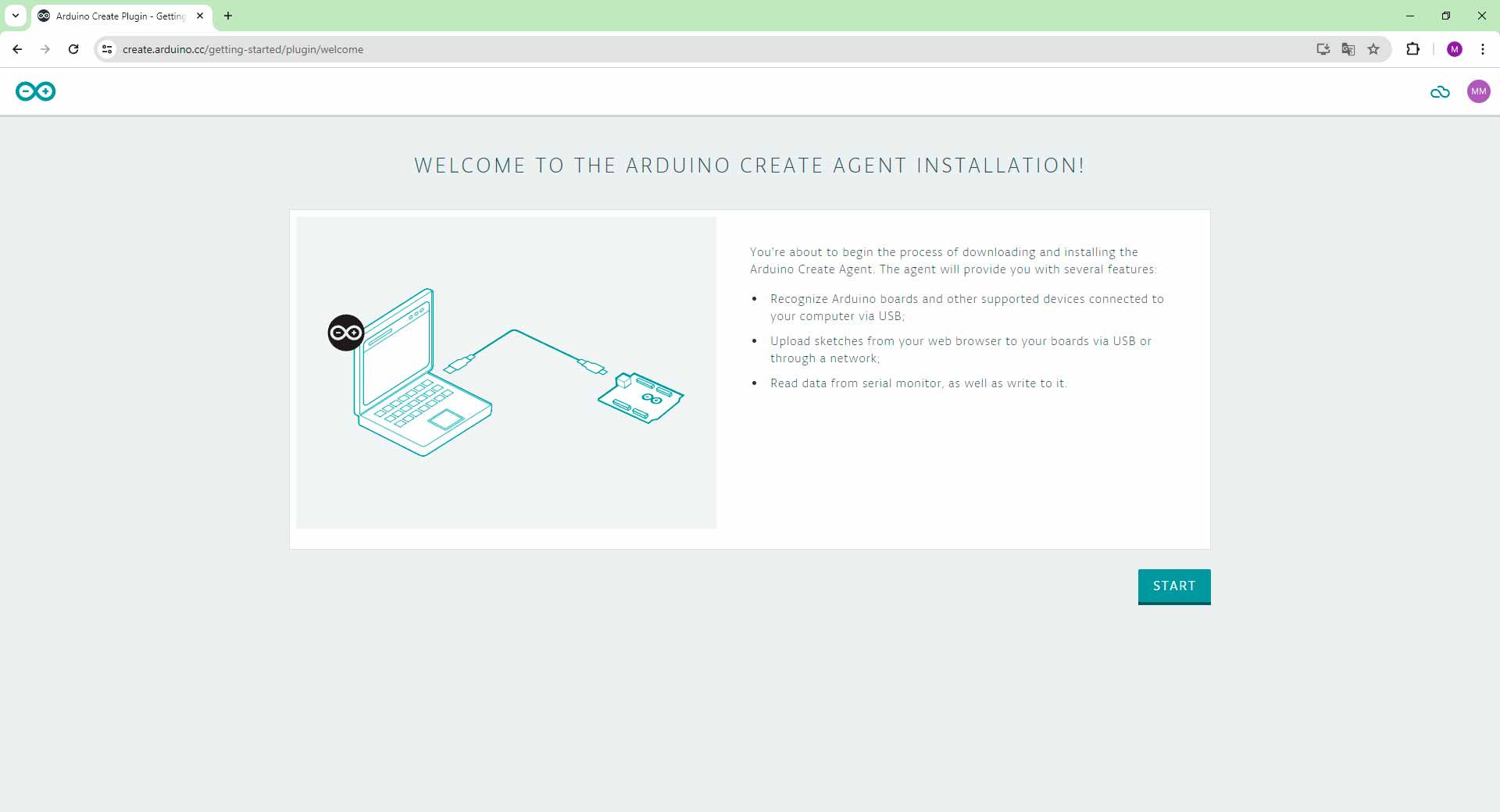
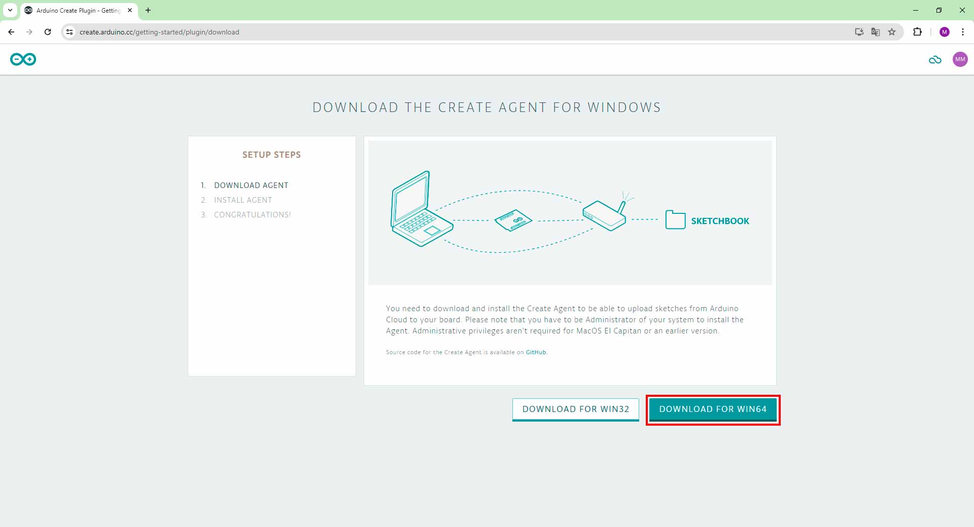
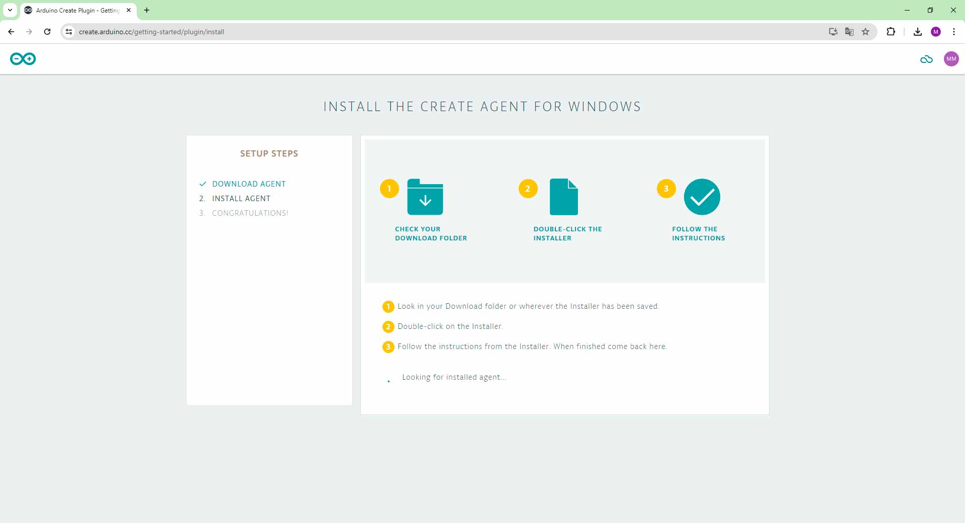
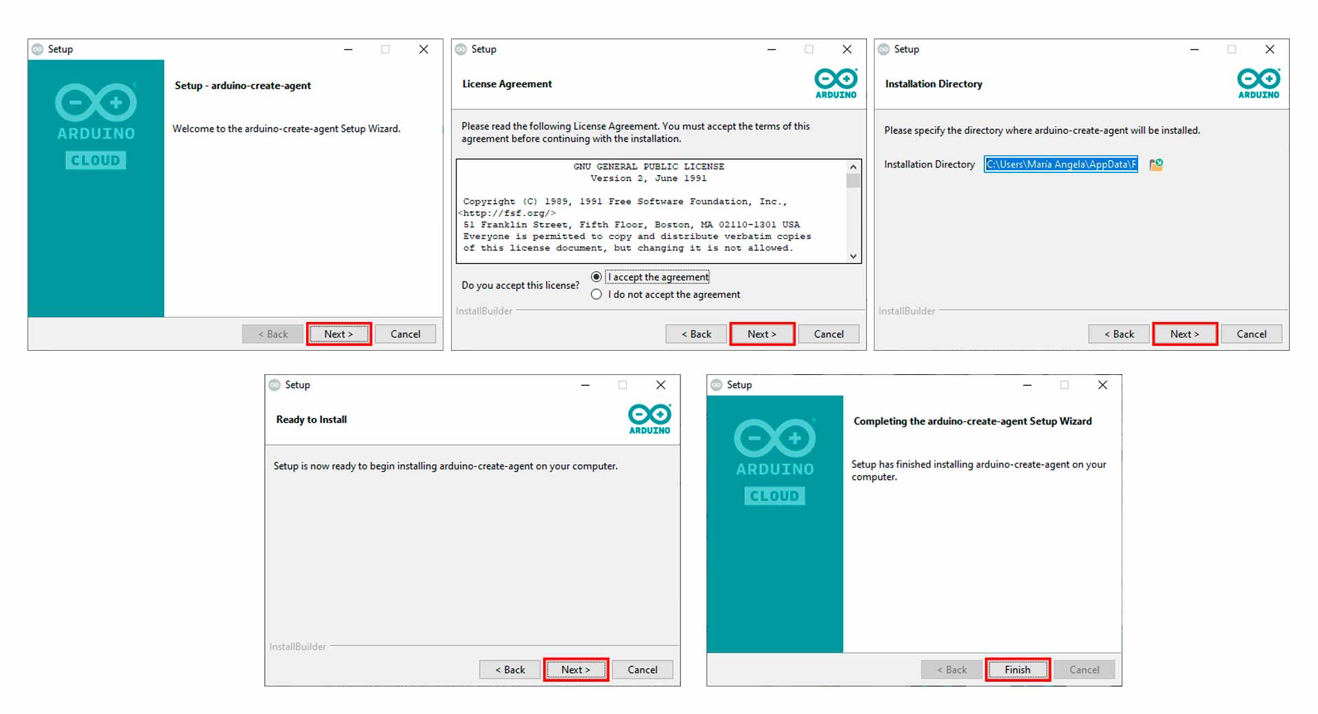
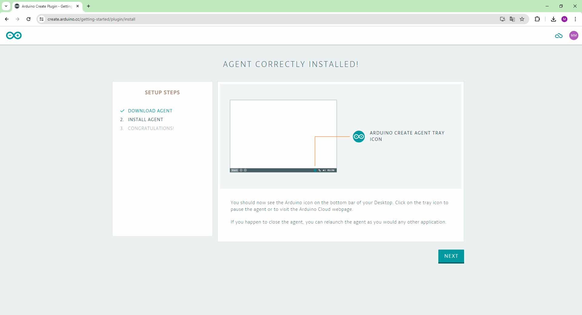
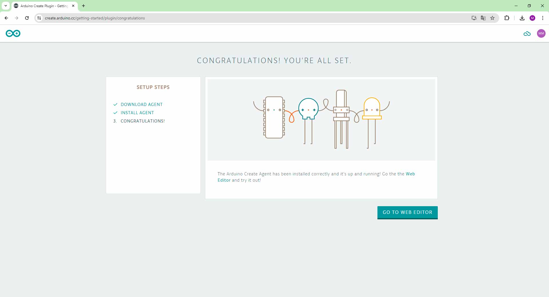
Installing Arduino Create Agent plugin
Configurating a Device and Network in Arduino IoT Cloud
Configuring a device and network in Arduino IoT Cloud involved several steps. I began by creating a thing. Afterward, I associated my XIAO ESP32C3 with this thing by selecting the appropriate device type and connecting it to the IoT Cloud. Next, I configured the network settings by specifying the Wi-Fi SSID and password that my device would use to connect to the internet. This setup enabled seamless communication between my device and the Arduino IoT Cloud.
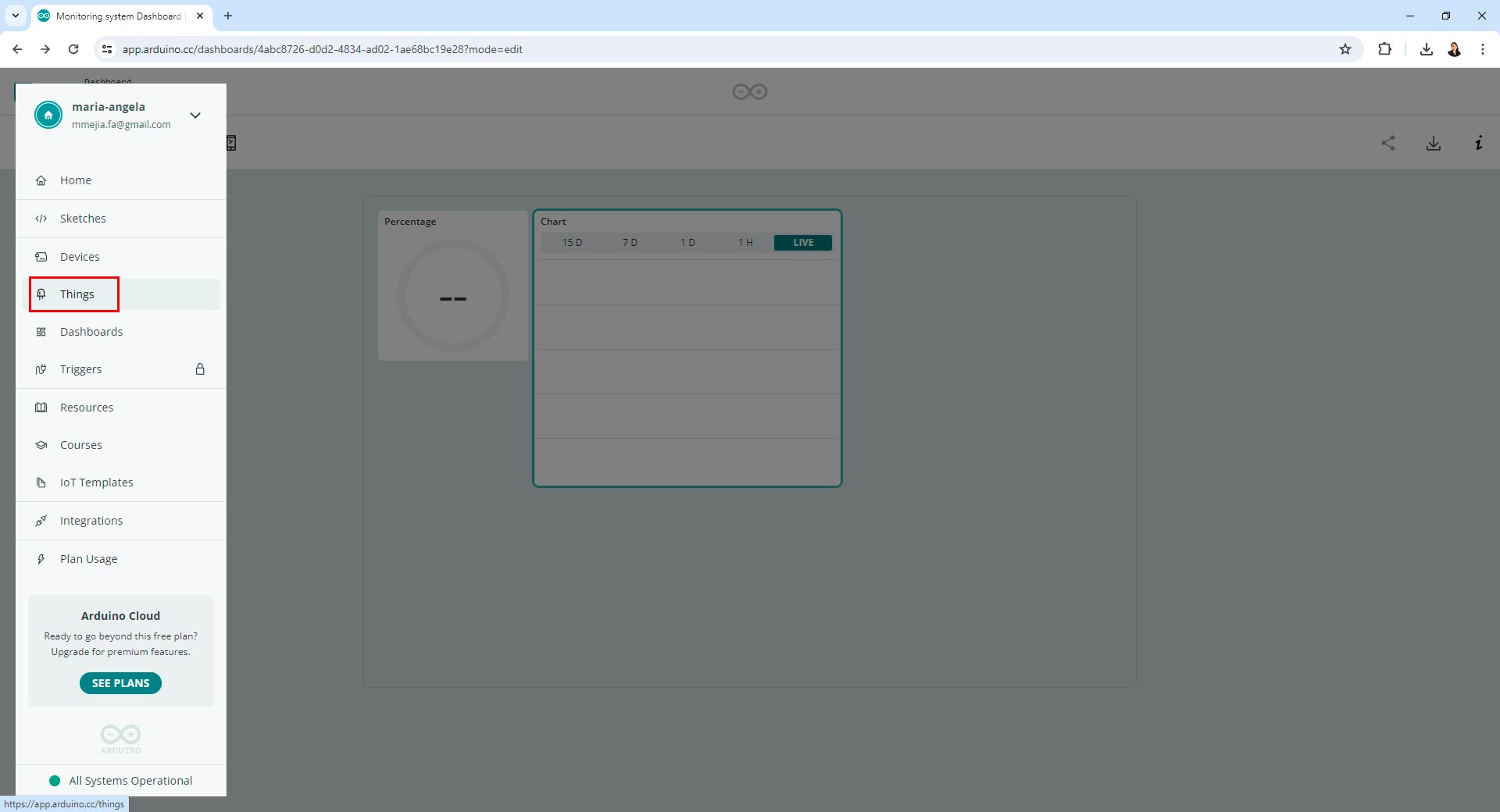
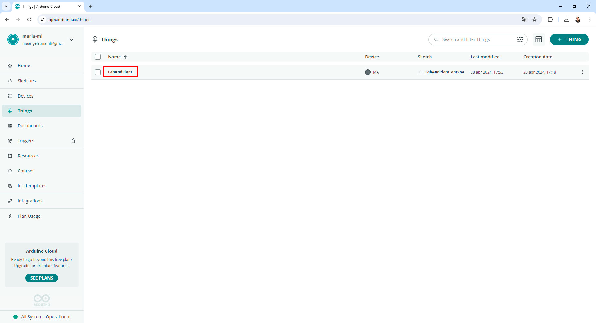
In the Arduino IoT Cloud, I started by creating a thing, a virtual representation of a physical device.
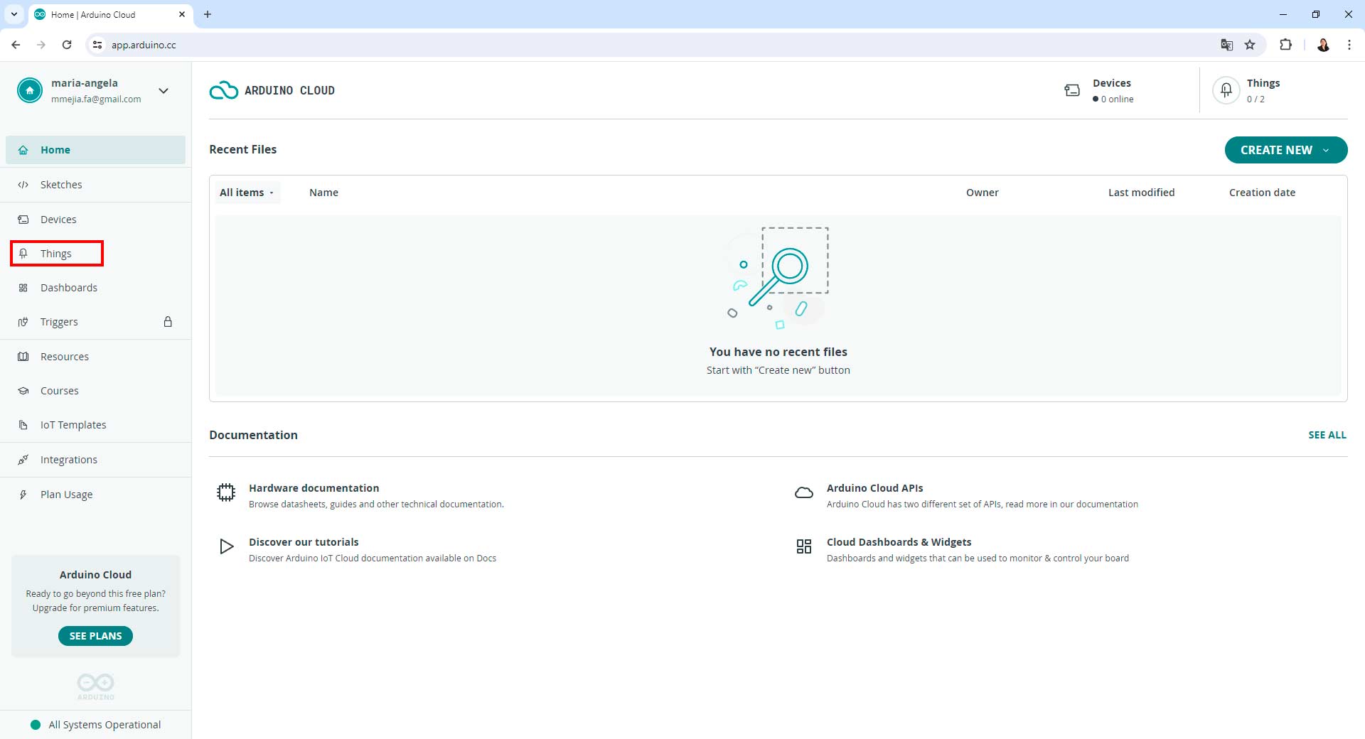
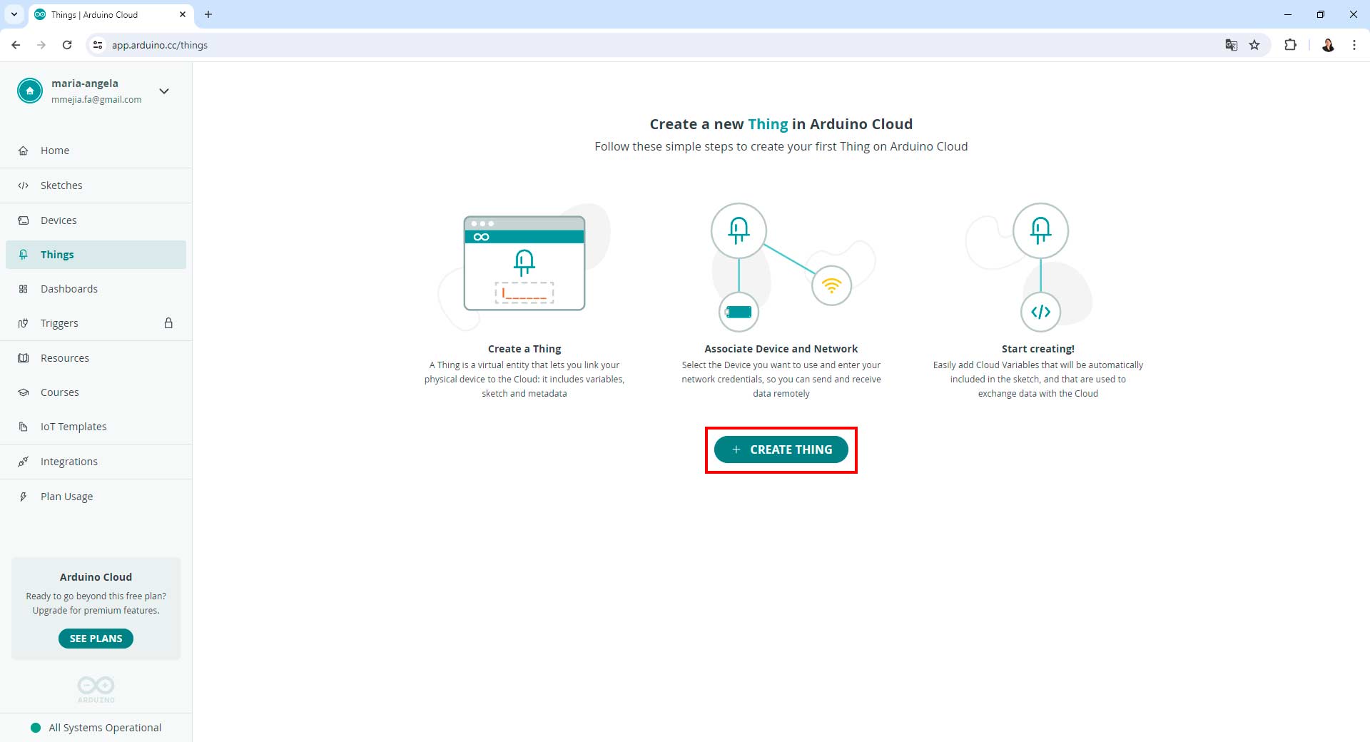
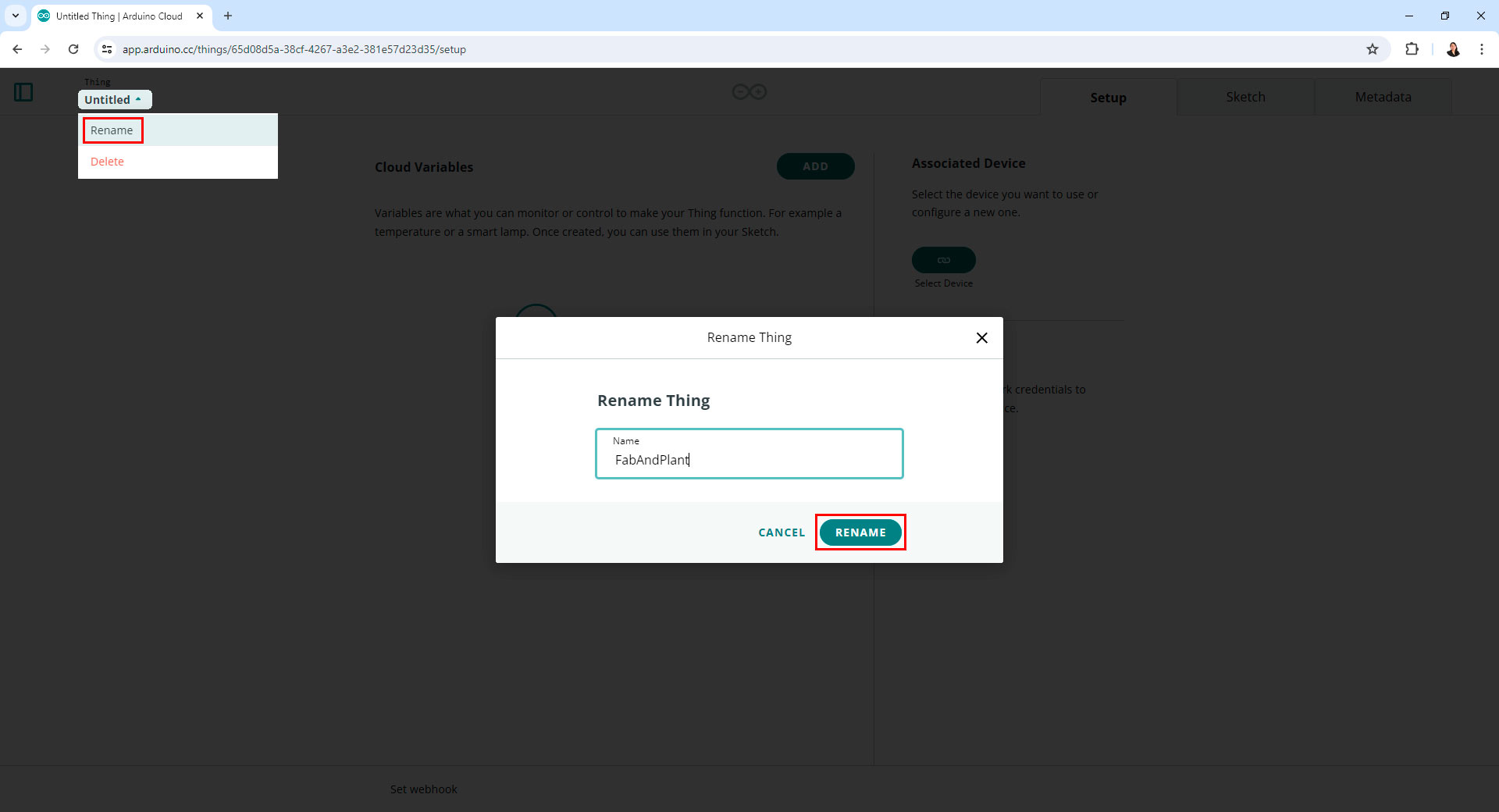
Creating a thing in Arduino IoT Cloud
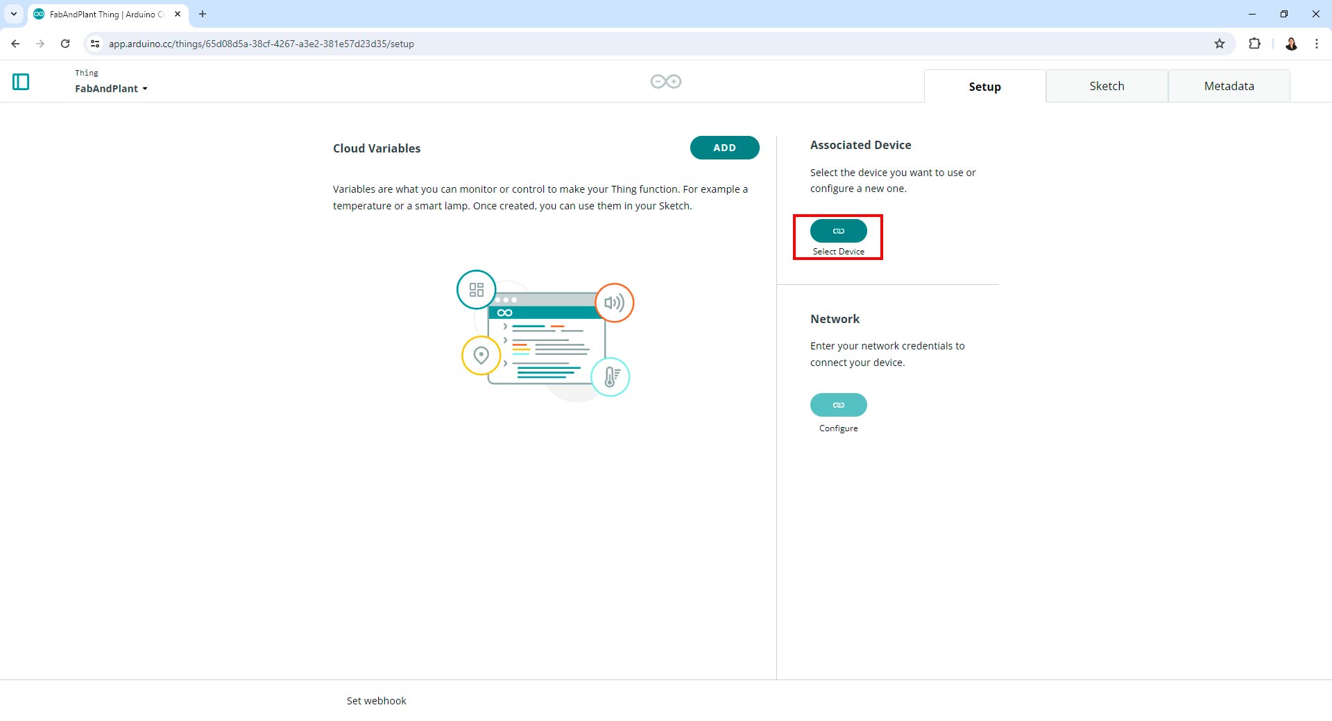
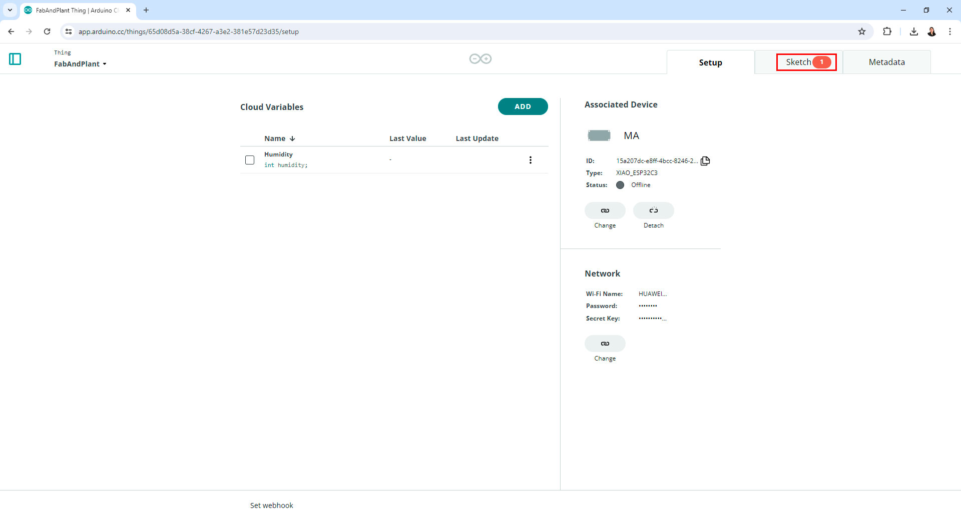
Once I created a thing, I associated a physical device with it. This process involved selecting the type of device I was using (e.g., Seeed XIAO ESP32C3) and connecting it to the IoT Cloud.
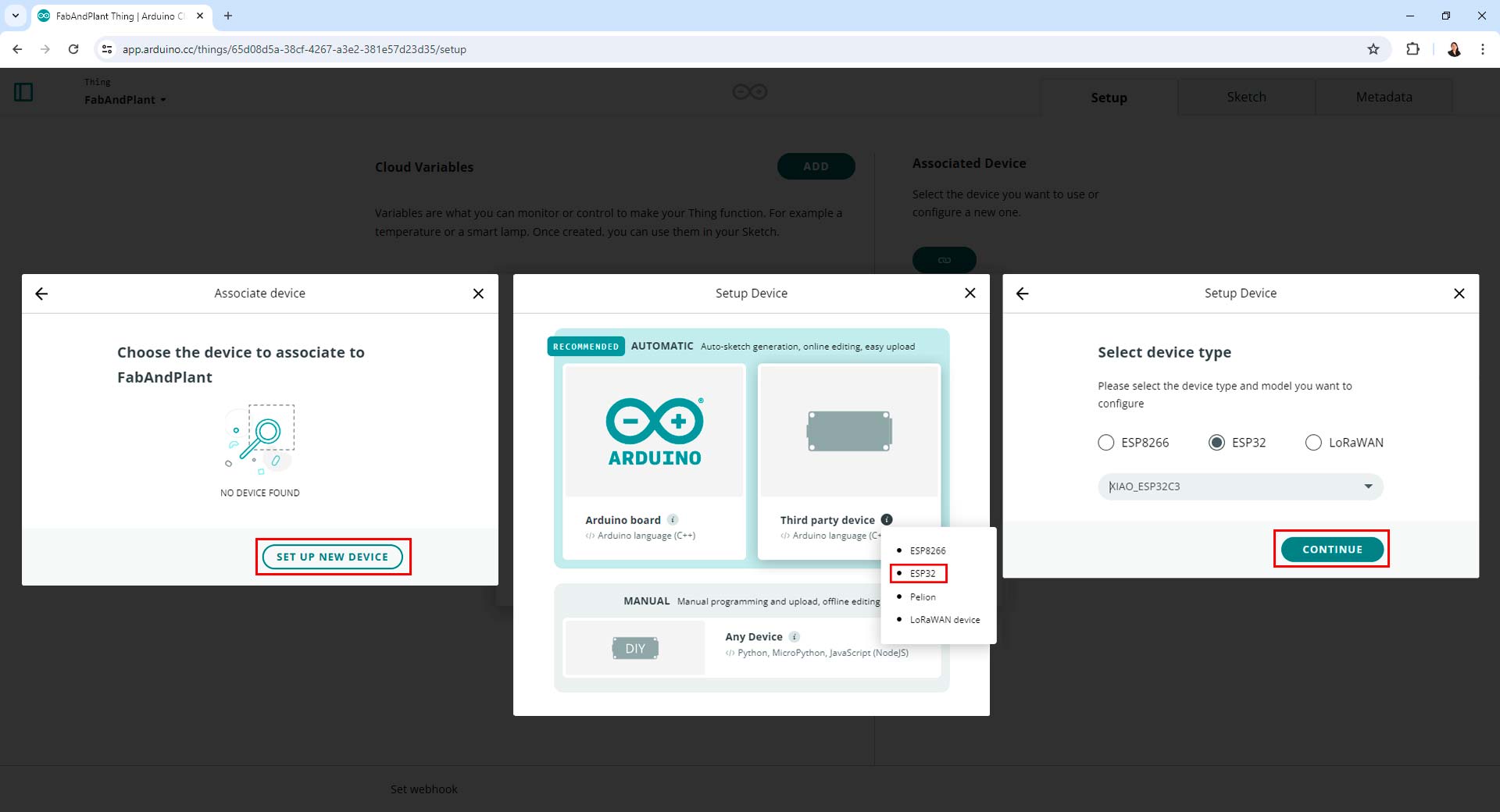
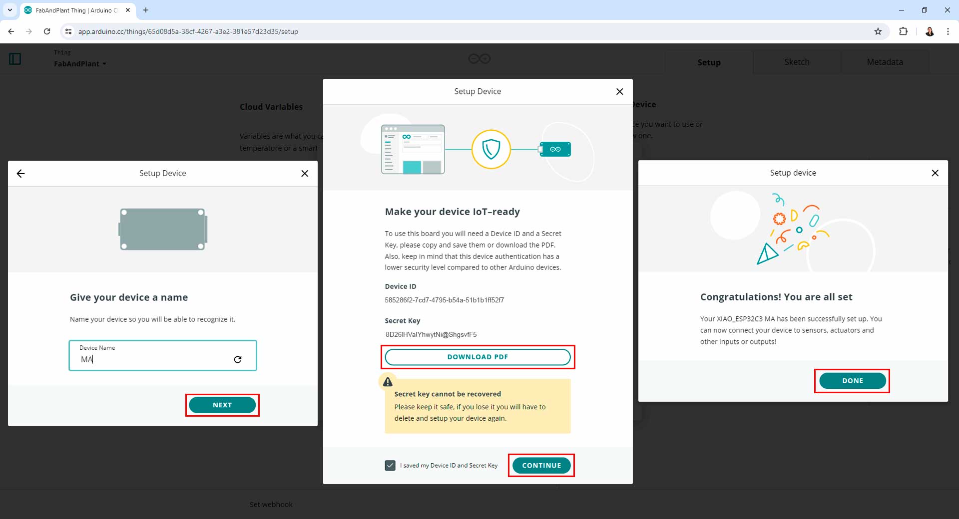
Associating a device in Arduino IoT Cloud
Next, I configured the network settings for my device. This included specifying the Wi-Fi SSID and password that my device would use to connect to the internet.
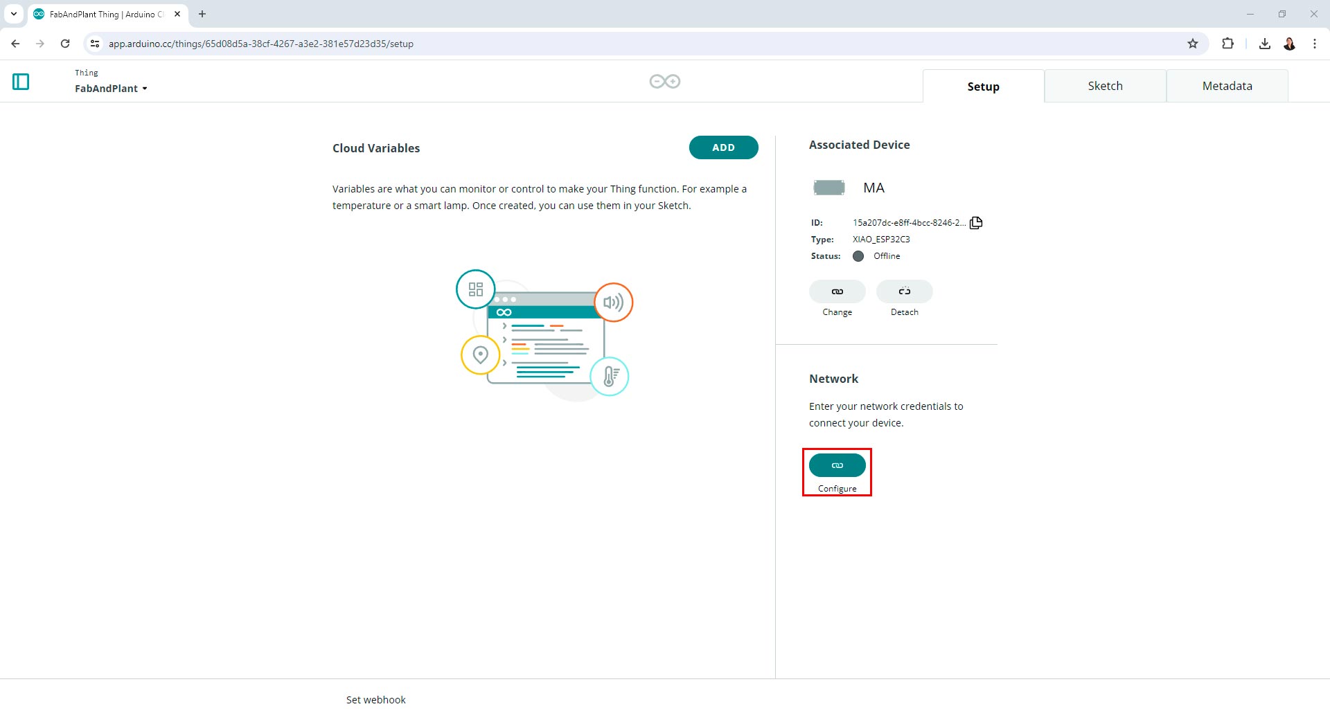
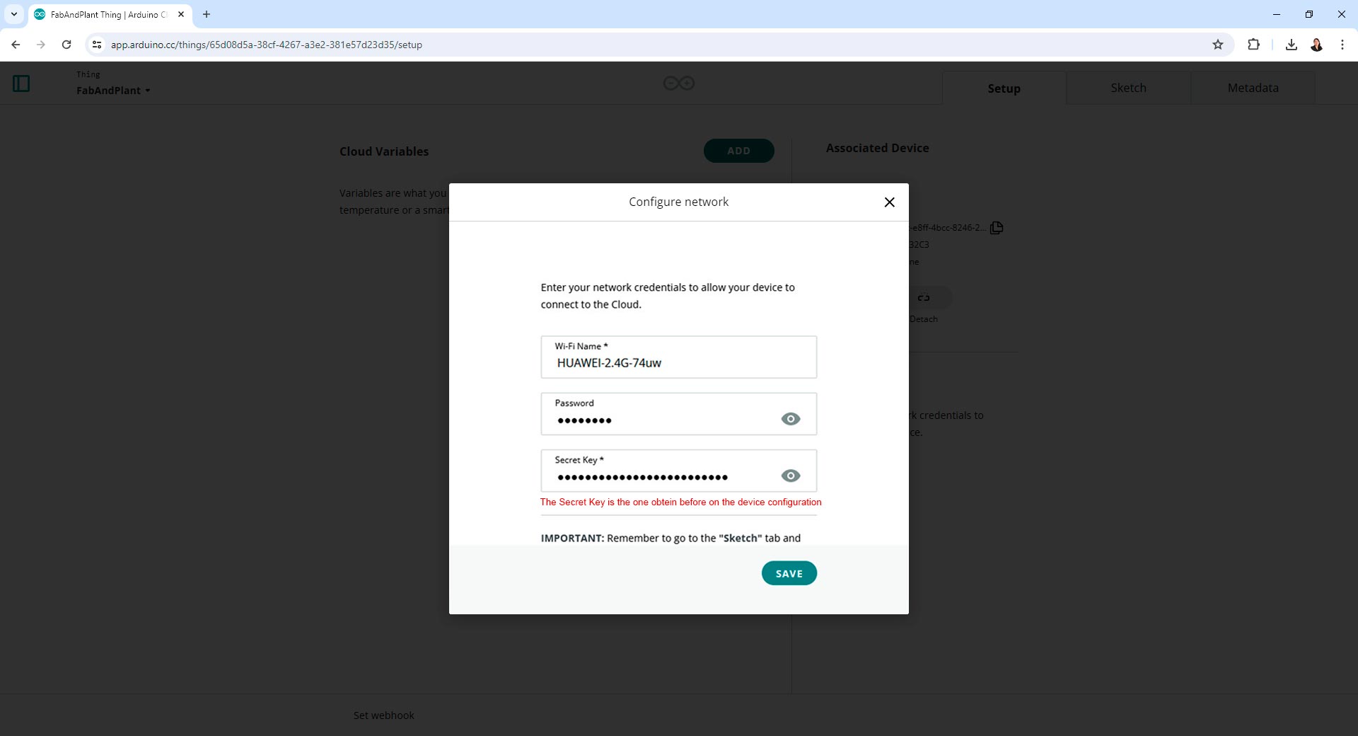
Configurating a network in Arduino IoT Cloud
Defining a Variable and Creating a Dashboard
I defined a variable in the Arduino IoT Cloud that would hold the sensor data. This variable was used to store and display the data on the dashboard.
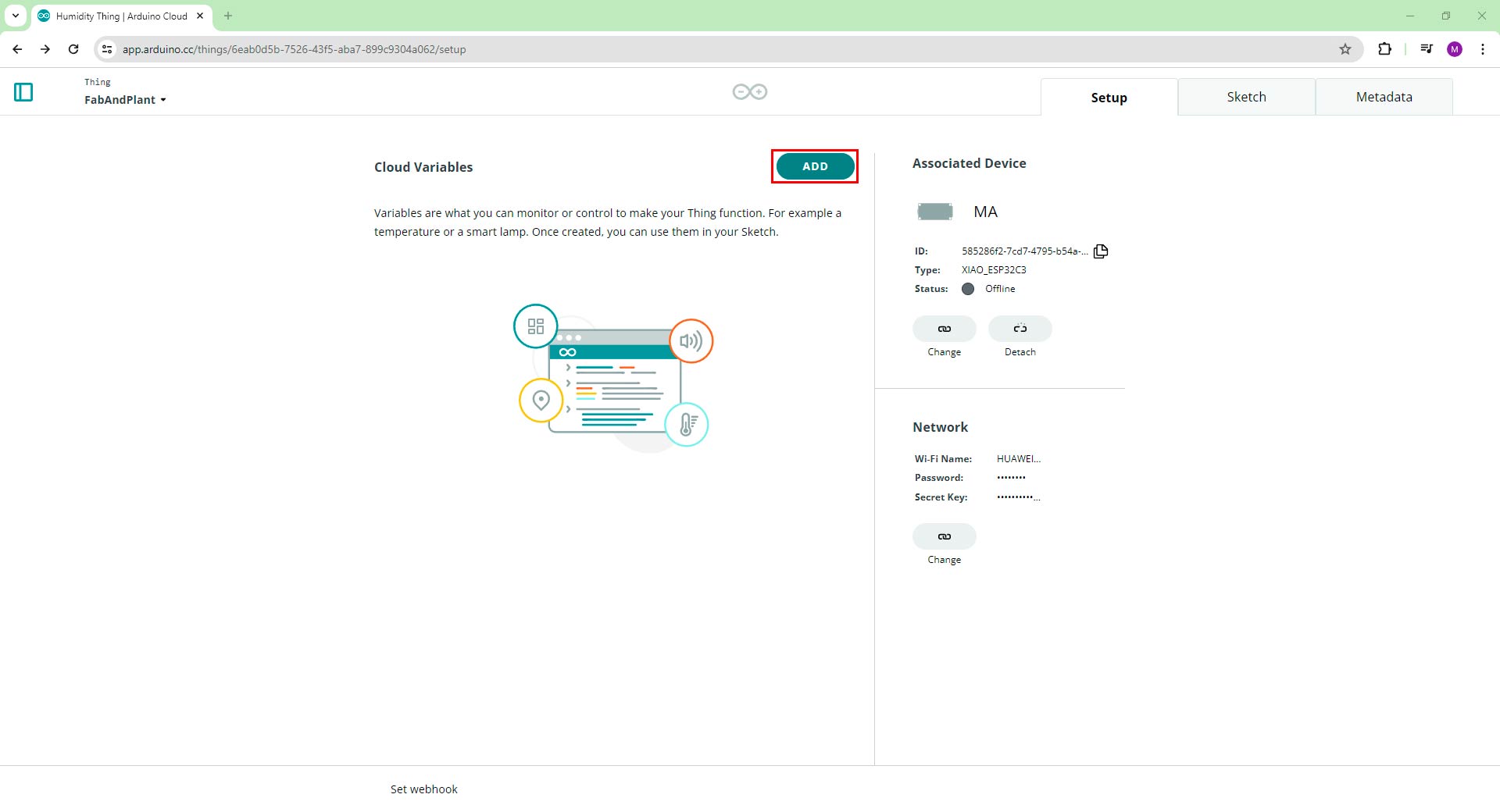
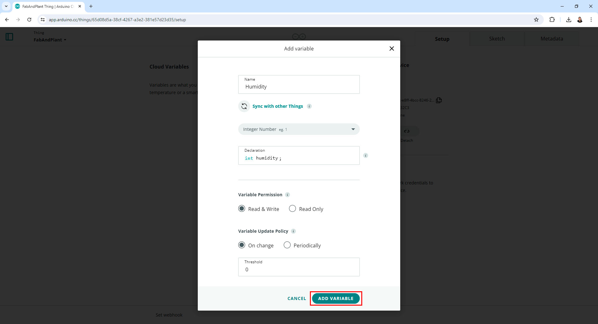
Adding a variable in Arduino IoT Cloud
The dashboard is where I could visually monitor the data from my sensor. I added widgets like percentage, and chart to represent the data and control the devices.
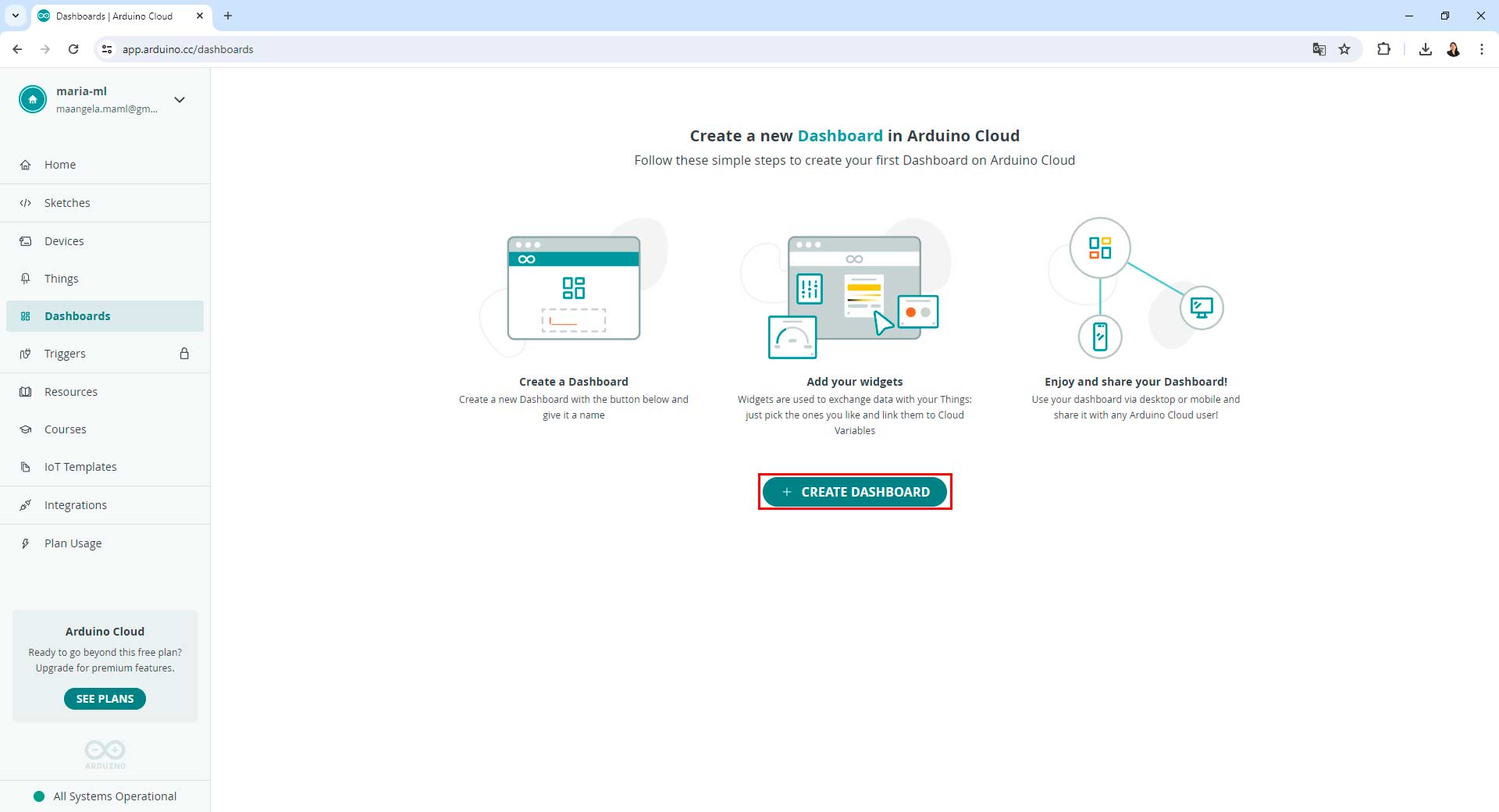
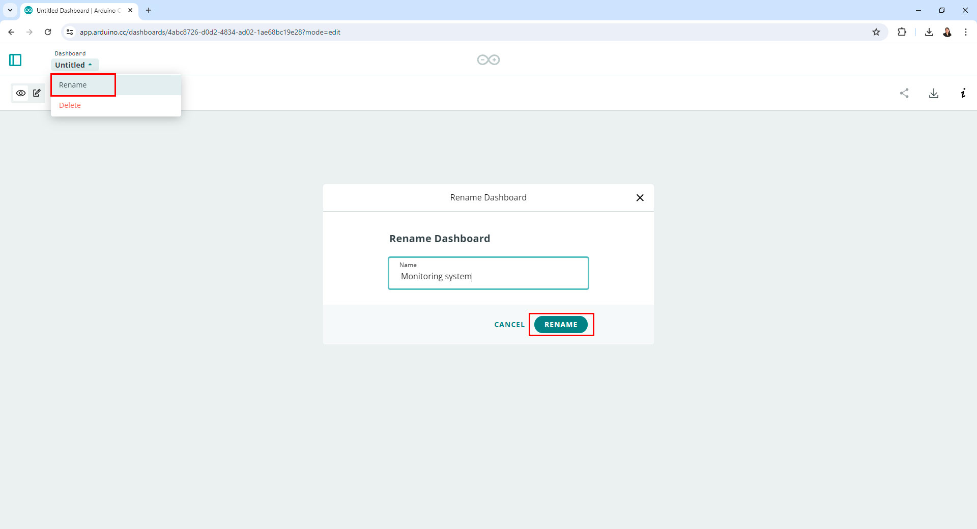
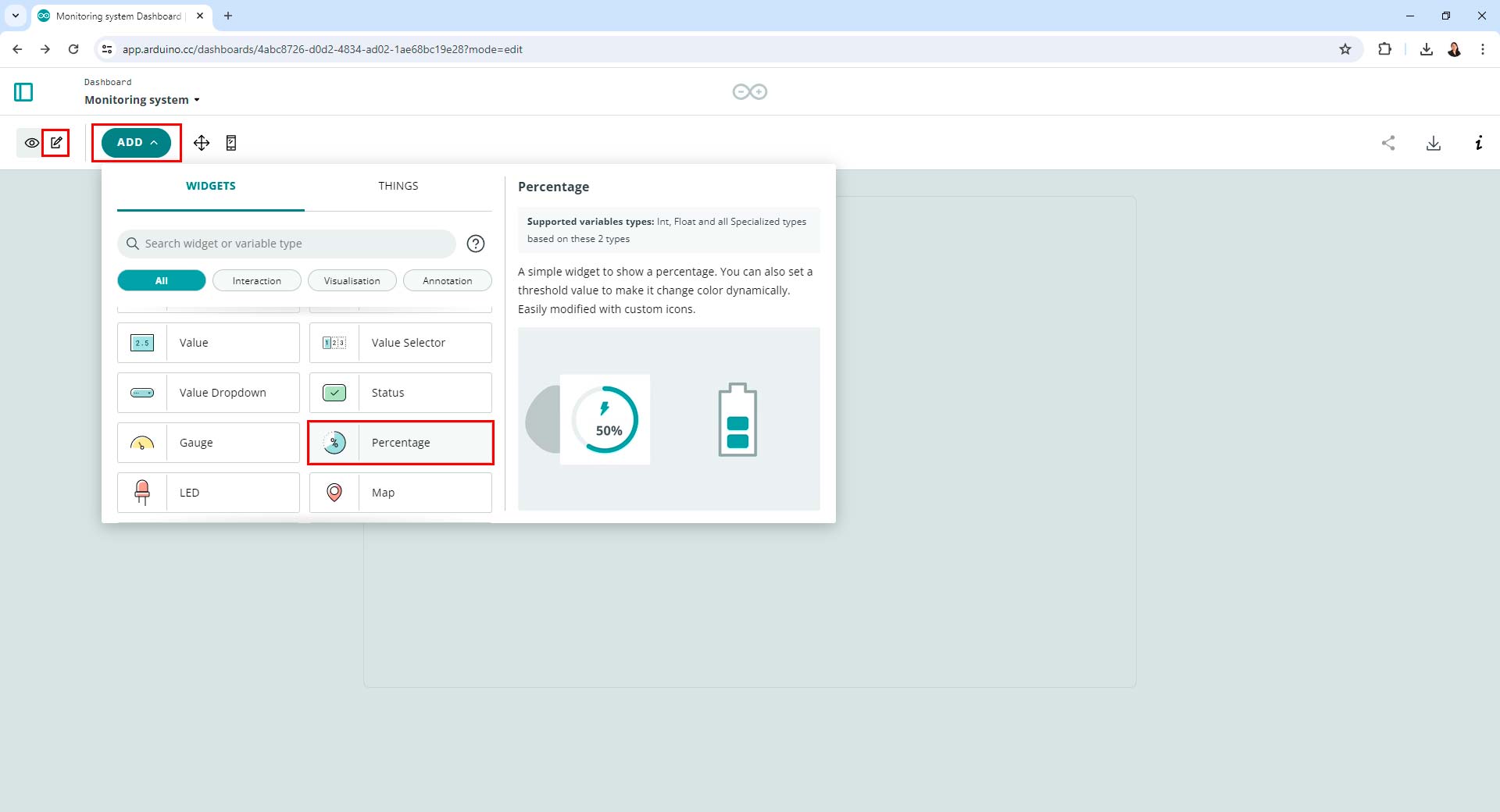
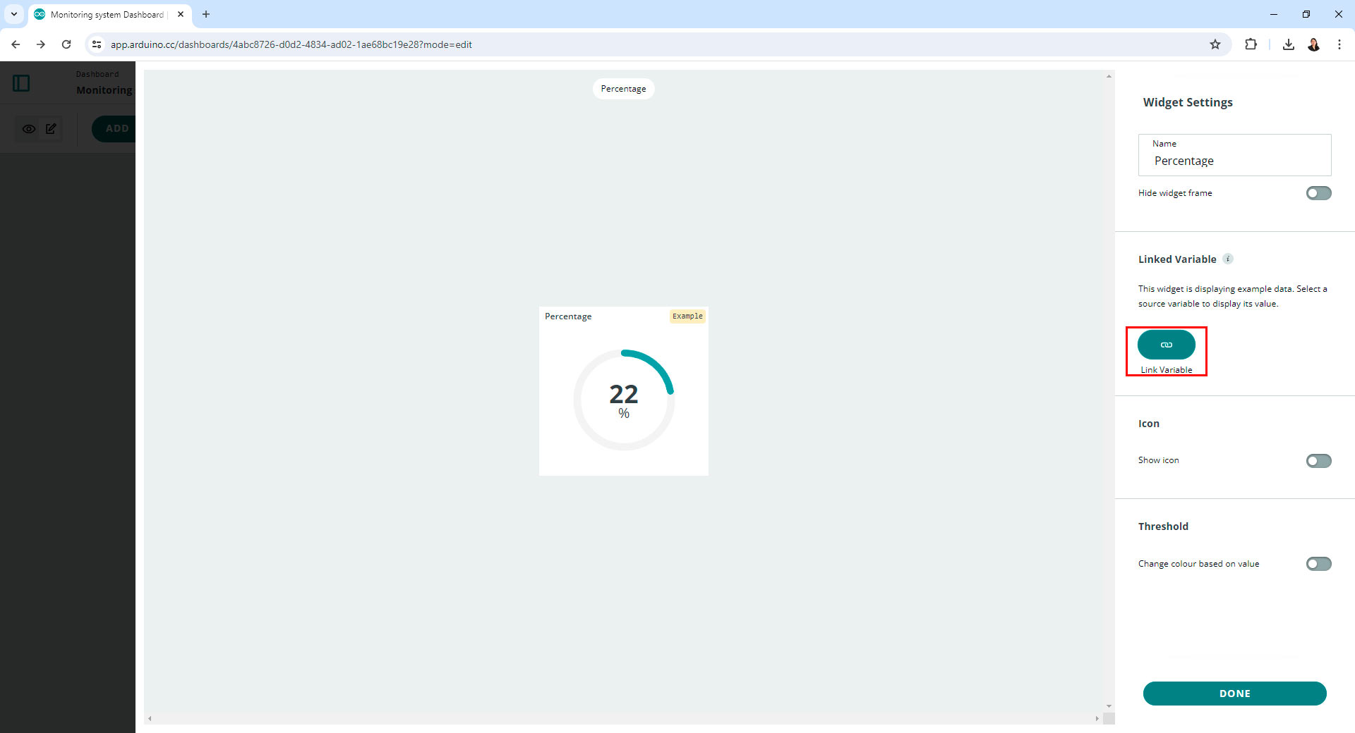
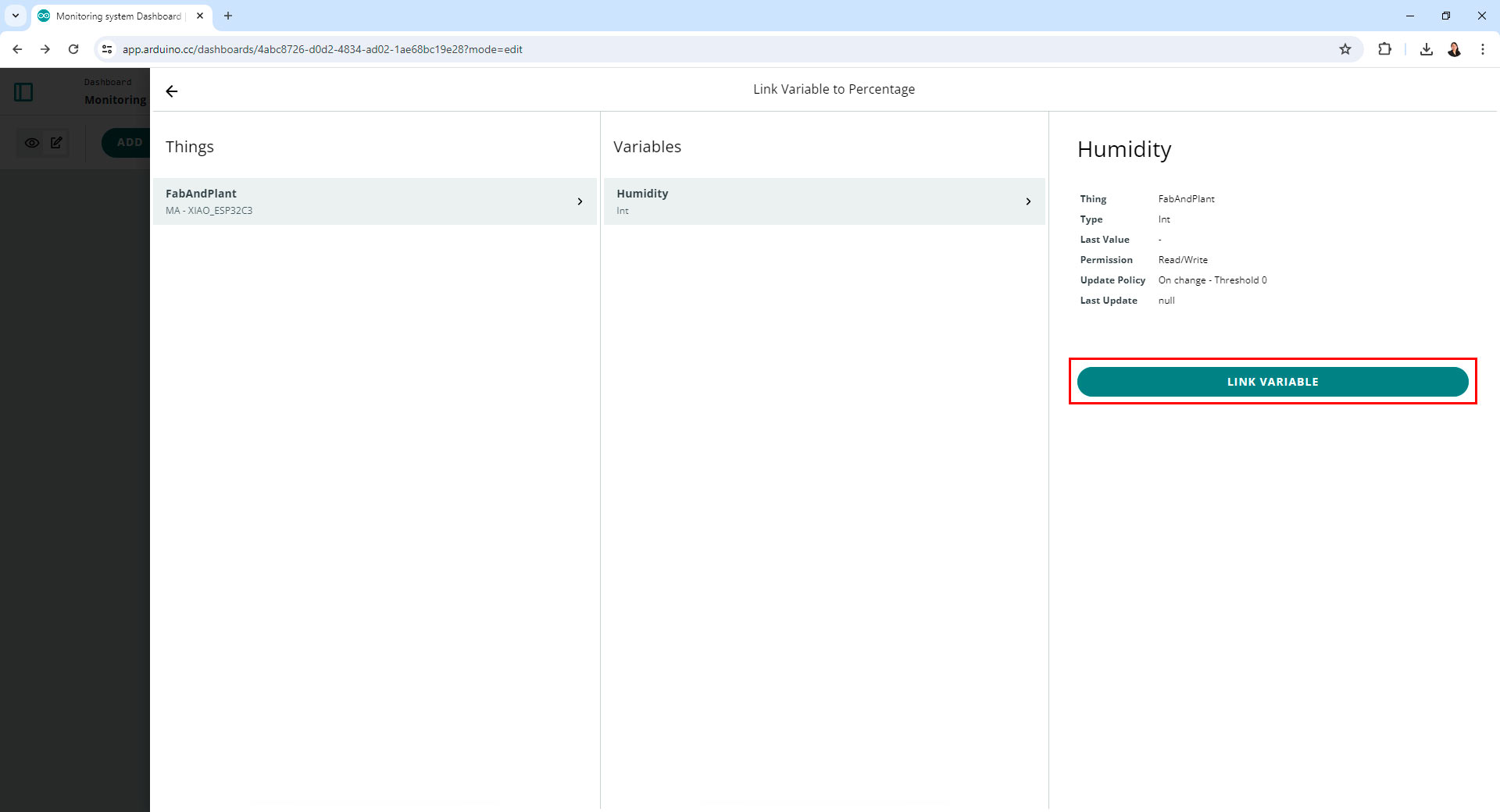
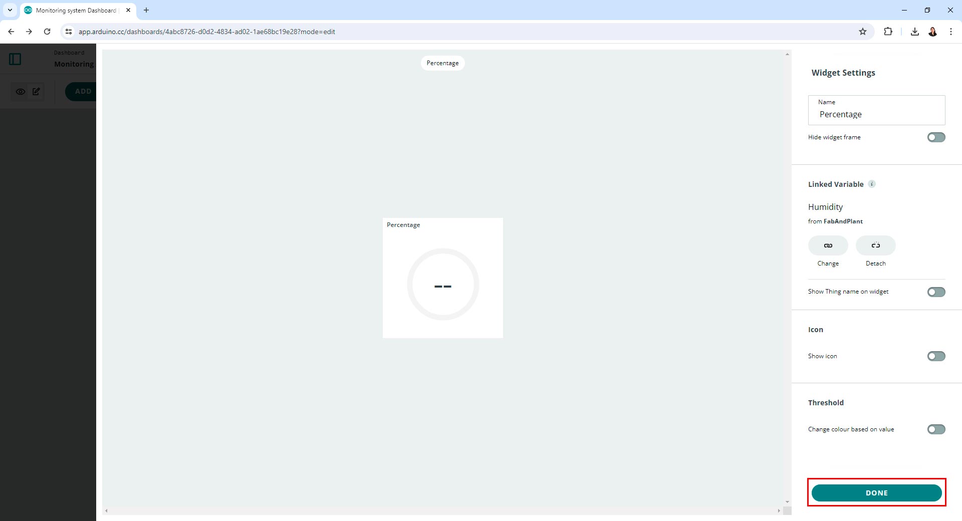
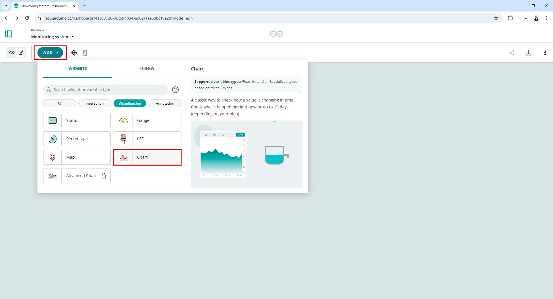
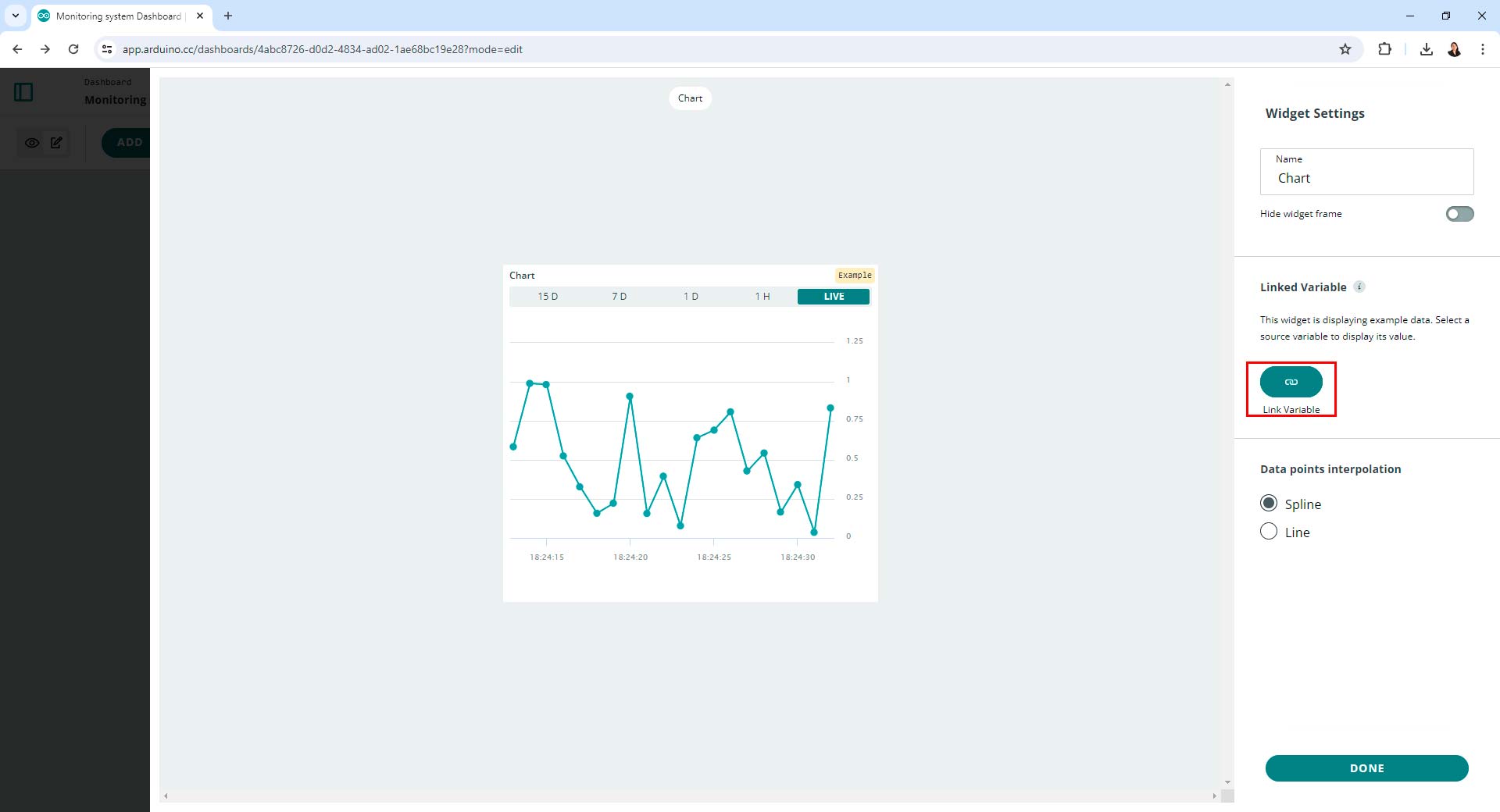

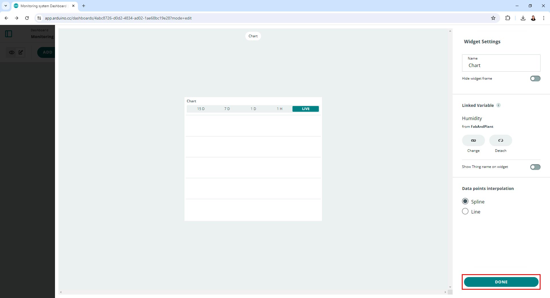
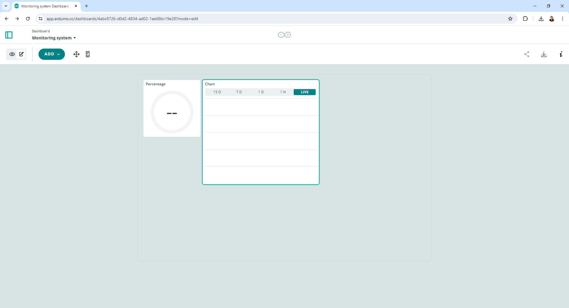
Creating a dashboard in Arduino IoT Cloud
Programming in Arduino IoT Cloud
Programming in Arduino IoT Cloud enables seamless integration of physical devices with the cloud, allowing for remote monitoring and control. This platform simplifies the process of connecting sensors and actuators, defining variables, and creating interactive dashboards. By utilizing Arduino IoT Cloud, I was able to efficiently gather and display hygrometer data from my XIAO ESP32C3.
For access and modify sketches in Arduino IoT Cloud, I navigated to the Sketch section of my project.
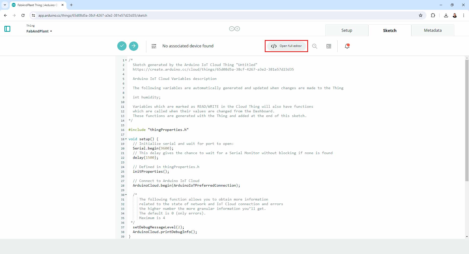
Programming in Arduino IoT Cloud
Then, I could view and edit the code that controlled my Seeed XIAO ESP32C3 with this code:
/*
  Sketch generated by the Arduino IoT Cloud Thing "Untitled"
  https://create.arduino.cc/cloud/things/6eab0d5b-7526-43f5-aba7-899c9304a062

  Arduino IoT Cloud Variables description

  The following variables are automatically generated and updated when changes are made to the Thing

  int humidity;
  int humidity2;

  Variables which are marked as READ/WRITE in the Cloud Thing will also have functions
  which are called when their values are changed from the Dashboard.
  These functions are generated with the Thing and added at the end of this sketch.
*/

#include "thingProperties.h"

void setup() {
  // Initialize serial and wait for port to open:
  Serial.begin(9600);
  // This delay gives the chance to wait for a Serial Monitor without blocking if none is found
  delay(1500);

  // Defined in thingProperties.h
  initProperties();

  // Connect to Arduino IoT Cloud
  ArduinoCloud.begin(ArduinoIoTPreferredConnection);

  /*
     The following function allows you to obtain more information
     related to the state of network and IoT Cloud connection and errors
     the higher number the more granular information you’ll get.
     The default is 0 (only errors).
     Maximum is 4
 */
  setDebugMessageLevel(2);
  ArduinoCloud.printDebugInfo();
}

void loop() {
  ArduinoCloud.update();
  // Your code here
  // constants
const int hygrometer = 4;  // hygrometer sensor analog pin output at pin A2 of XIAO ESP32-C3
// variables

  humidity2 = analogRead(A2);     // read analog value
  humidity2 = constrain(humidity2,400,1023);  // keep the ranges
  humidity2 = map(humidity2,400,1023,100,0);  // map value: 400 will be 100 and 1023 will be 0
  Serial.print("Soil humidity: ");
  Serial.print(humidity2);
  Serial.println("%");
  delay(10000);                       // read every 10 seconds

}

/*
  Since Humidity2 is READ_WRITE variable, onHumidity2Change() is
  executed every time a new value is received from IoT Cloud.
*/
void onHumidity2Change()  {
  // Add your code here to act upon Humidity2 change
}


/*
  Since Humidity is READ_WRITE variable, onHumidityChange() is
  executed every time a new value is received from IoT Cloud.
*/
void onHumidityChange()  {
  // Add your code here to act upon Humidity change
}
Code in Arduino IoT Cloud
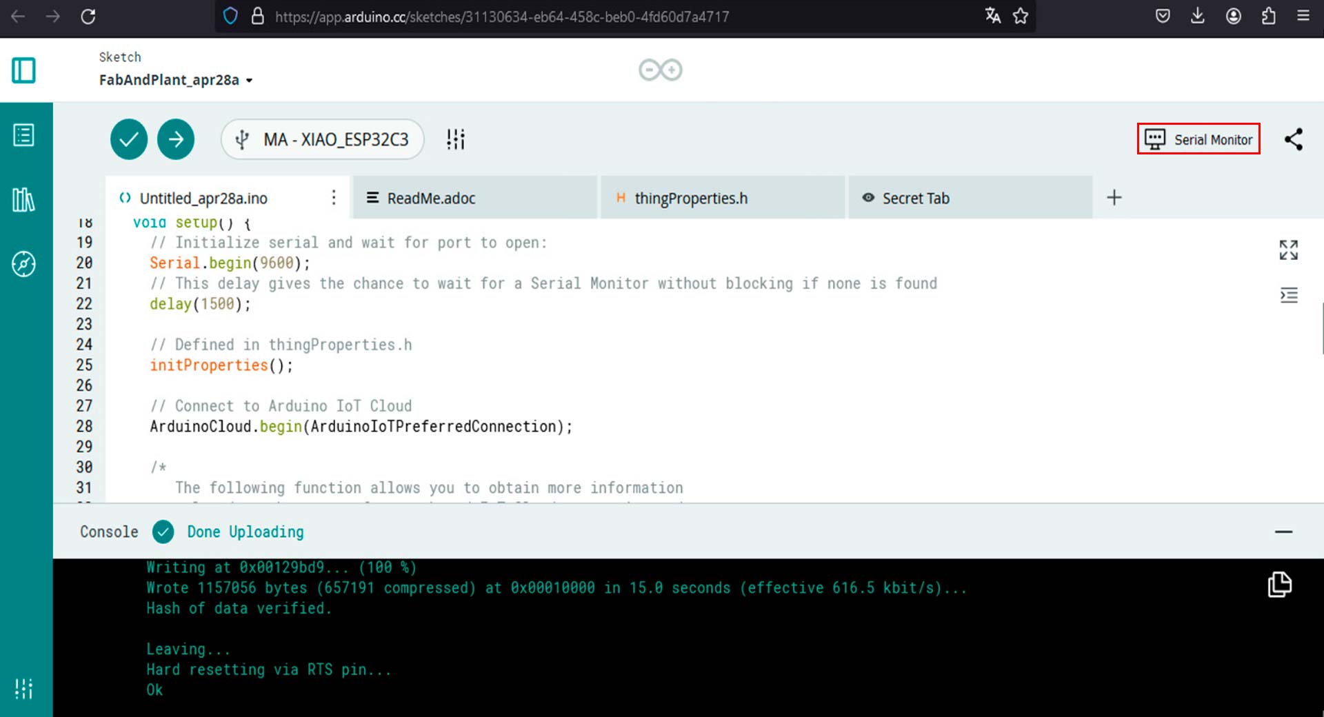
Once I made the changes I needed, I saved the modifications and deployed the updated sketch to my device. Finally, I started the serial monitor in Arduino IoT Cloud.
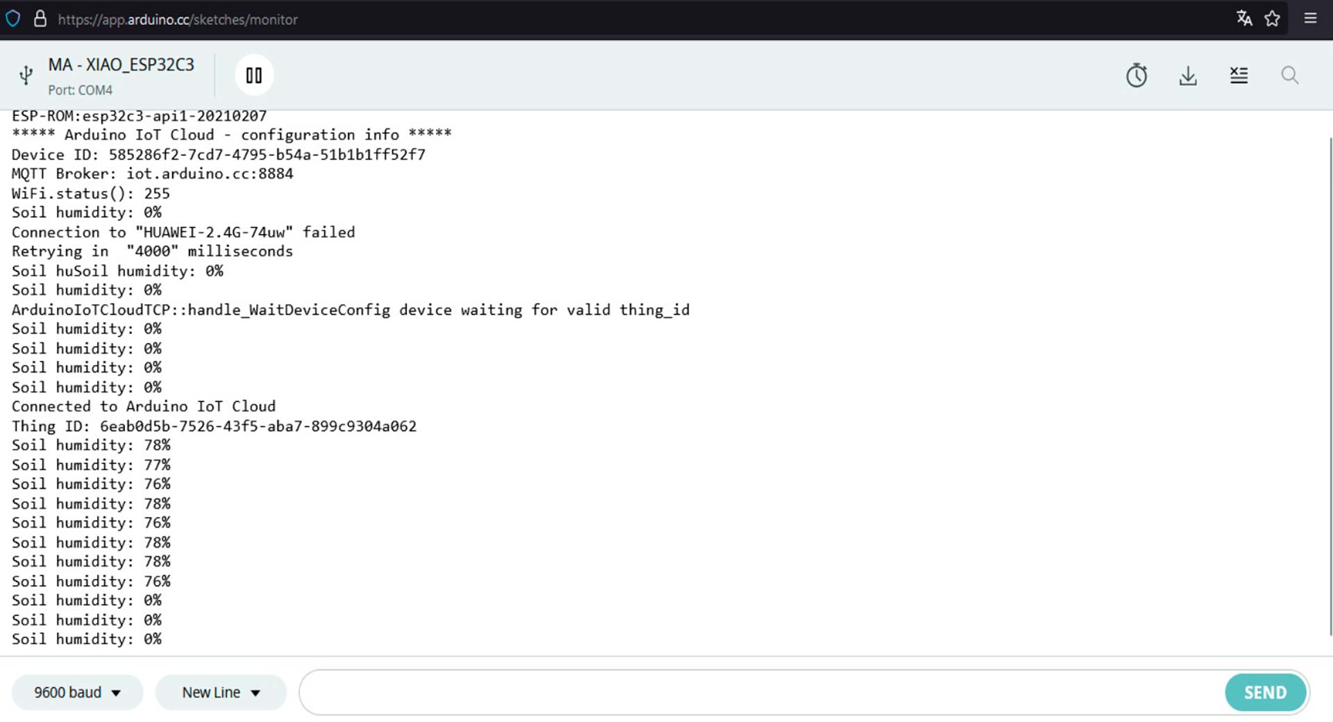
Arduino IoT Cloud serial monitor
Dashboard with data in Arduino IoT Cloud
I encountered several connection difficulties during this task. The longest to resolve was a simple issue: keeping the Arduino IDE serial monitor open while programming in Arduino IoT Cloud causes conflicts. Once this was resolved, the remaining issues were related to the code and the internet connection, which took some time to establish. Finally, after some debugging work, it worked!
Group Assignment: Message Between Projects
The group assignment page is here.
What I Learned From Team Work
This part of the week's assignment was especially challenging because I encountered several problems connecting two boards with the XIAO ESP32-C3 microcontrollers. During my meeting with colleagues to complete the task, the microcontrollers often failed to connect to the network, recognize the port, or run the programming correctly. I spent considerable time debugging these issues, which ranged from soldering problems to programming errors. However, the main problem -as Prof. Neil Gershenfeld later informed us in class- is that the XIAO ESP32-C3 tends to have these issues when programmed with the Arduino IDE. It is better to use MicroPython. Despite many attempts, I eventually managed to establish a connection between two boards using the Arduino IDE. For future projects, I recommend trying MicroPython first.
Designing, milling and soldering a PCB
Initially, I worked only with the Fab&Plant PCB and the XIAO ESP32-C3. Due to the problems mentioned earlier, I decided to create another board for this part of the assignment.
On this PCB, I included a button, an LED, and the I2C and UART connections that my previous boards did not have. I then used the MODS platform to generate the files needed to mill the board.
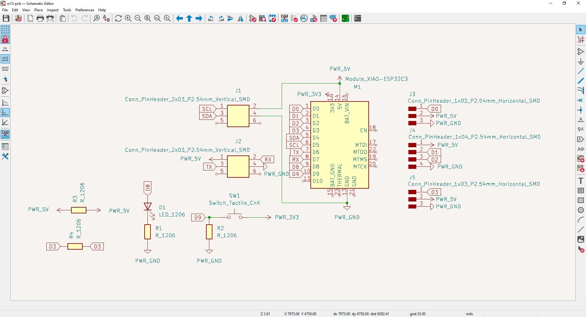
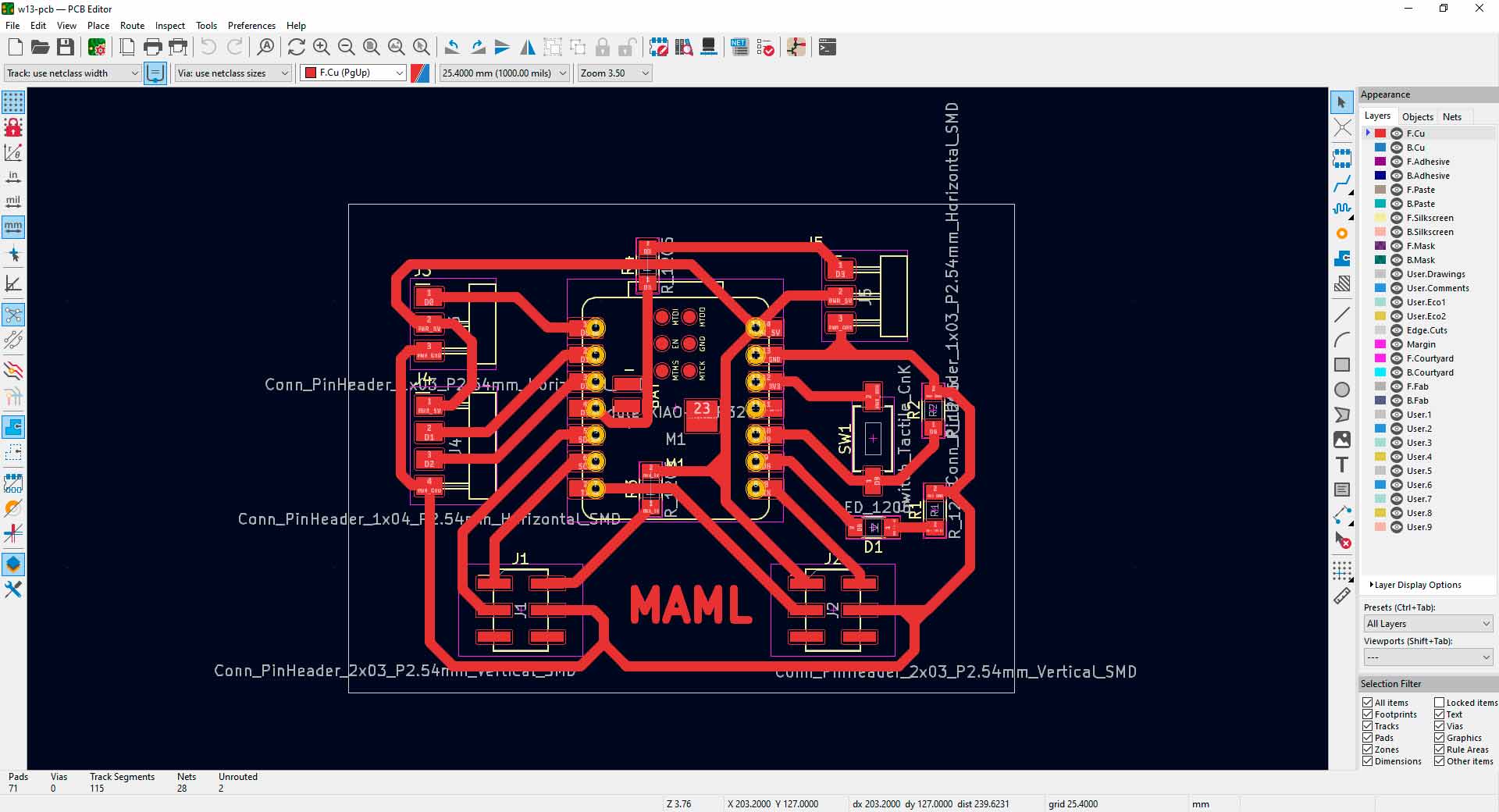
PCB design in KiCad
To use the router machine for milling the PCB, I went to Universidad Cientifica del Sur (UCSUR) Fab Lab which is located in the architecture faculty of the university, in Chorrillos district, in Lima, Peru. There, I also soldered it.
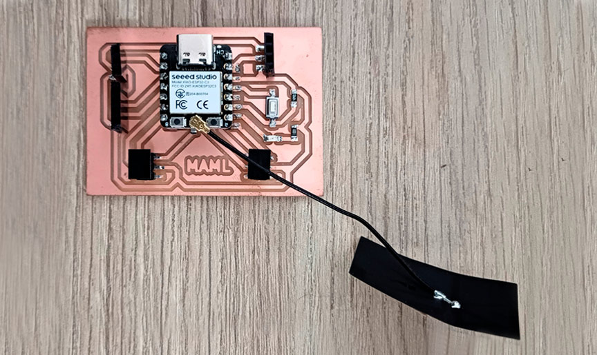
Finnished PCB
Connecting Boards Using MQTTX and Arduino IDE
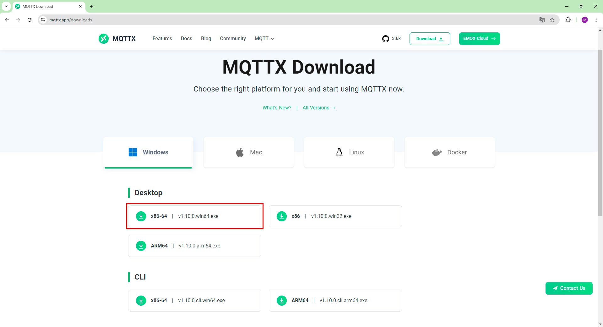
Following my tutors' recommendation, I tried using MQTTX. This platform has servers that enable message communication between microcontrollers or boards through a channel. It is an open-source MQTT 5.0 desktop client built with Node.js and Electron. It provides a graphical user interface (GUI) for interacting with MQTT brokers.
First, I downloaded and installed the software from here. Then, I opened it, created a new connection and subscription, and verified message sending and receiving.
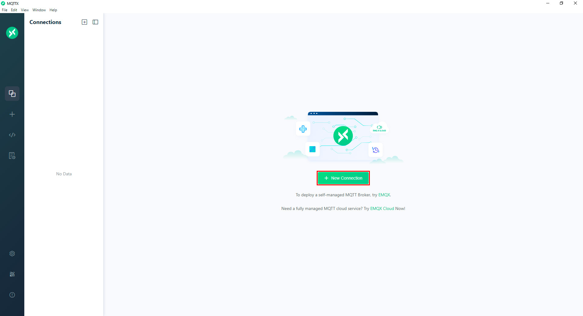
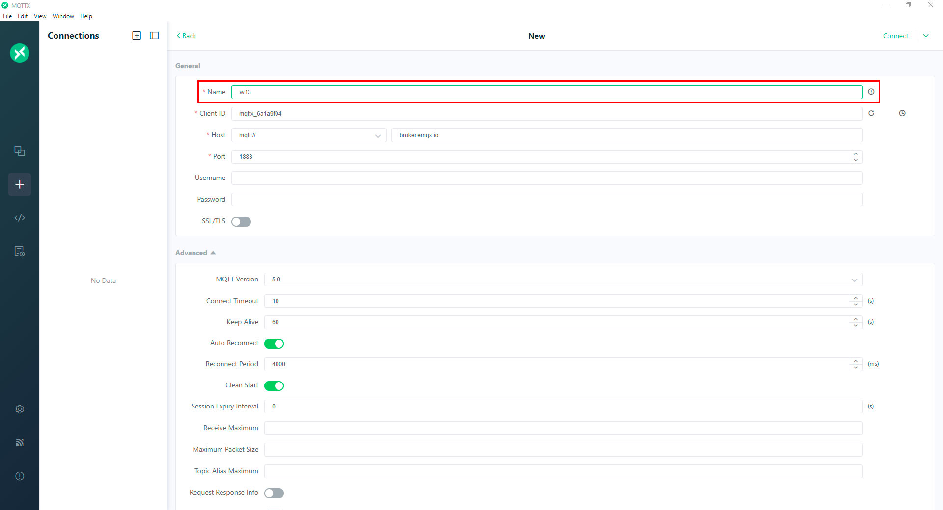
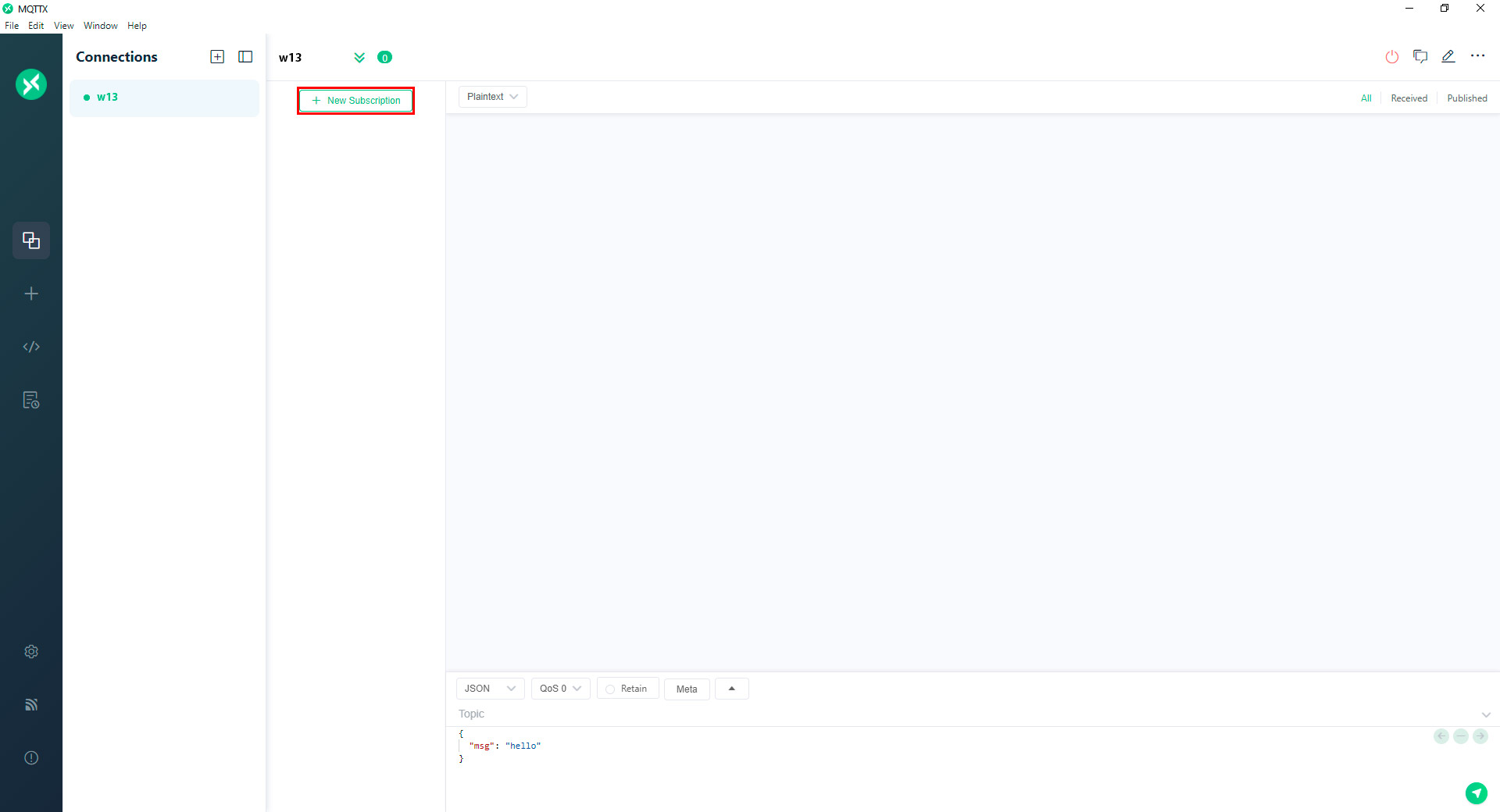
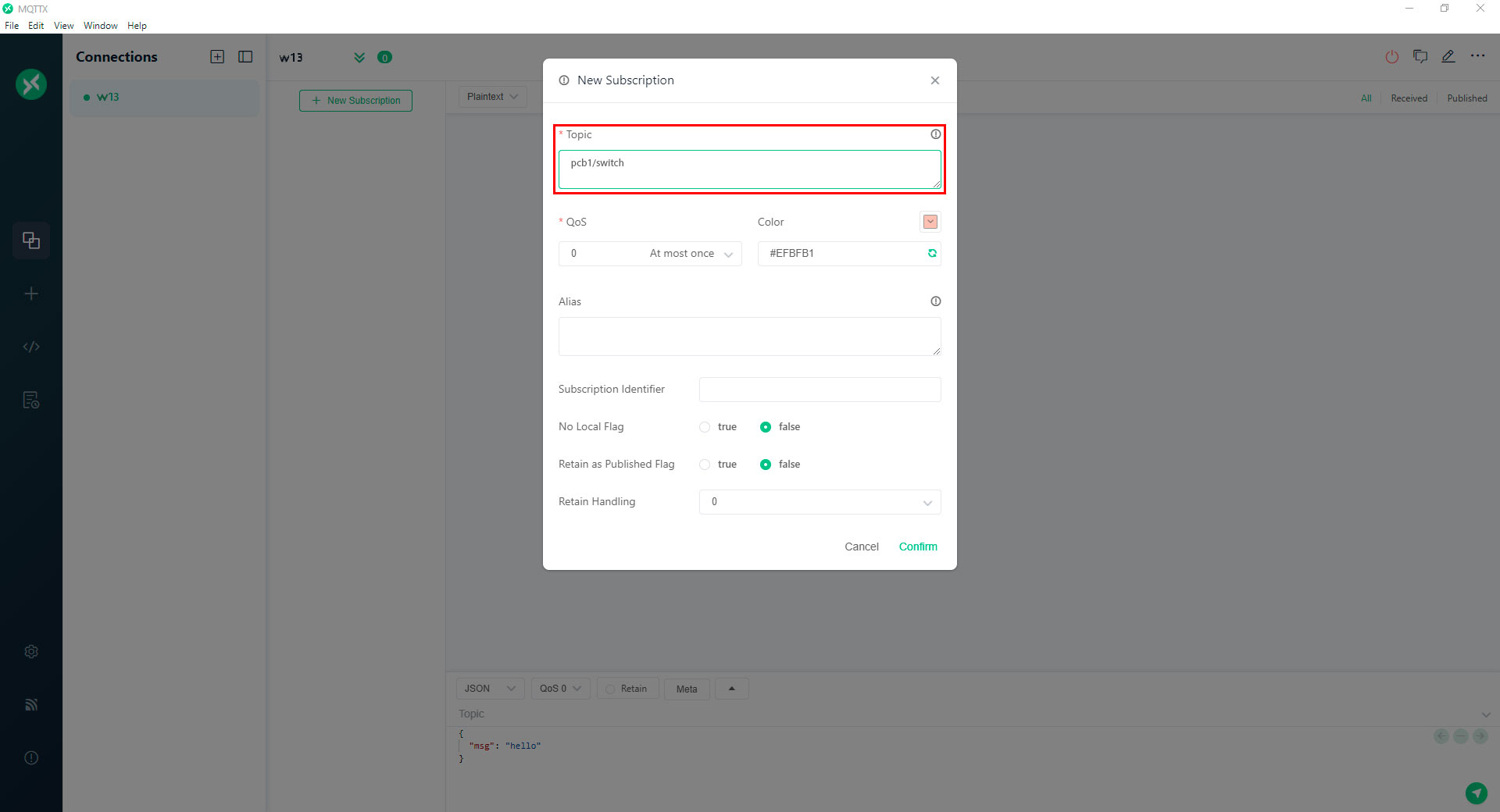
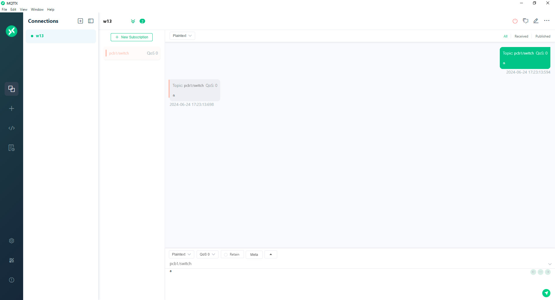
Using MQTTX
I made this procedure on both the new PCB I created and the existing Fab&Plant PCB. To avoid the connection issues I faced previously when working with my colleagues, I decided to perform the exercise independently first.
With the microcontrollers connected to MQTTX, they were ready to be programmed. To start, I installed the PubSubClient and ESP32Servo libraries in Arduino IDE as follows:
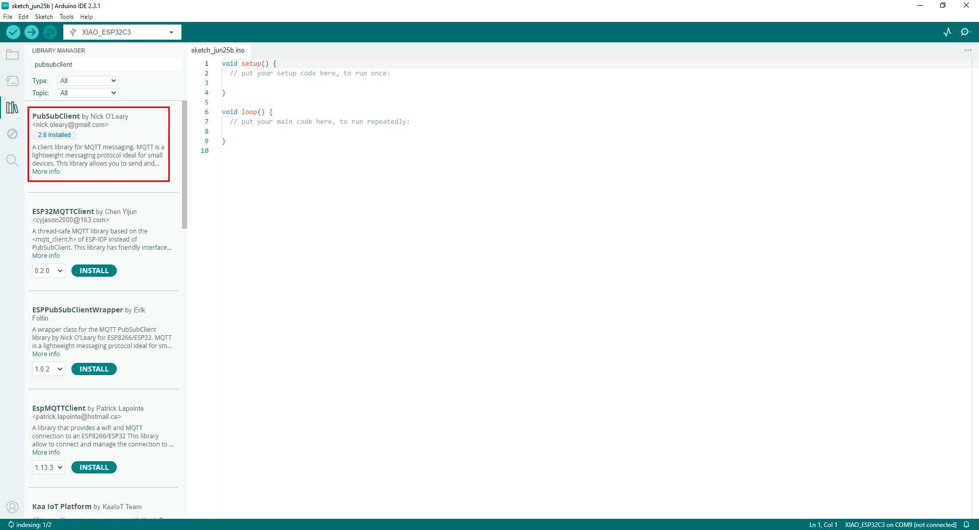
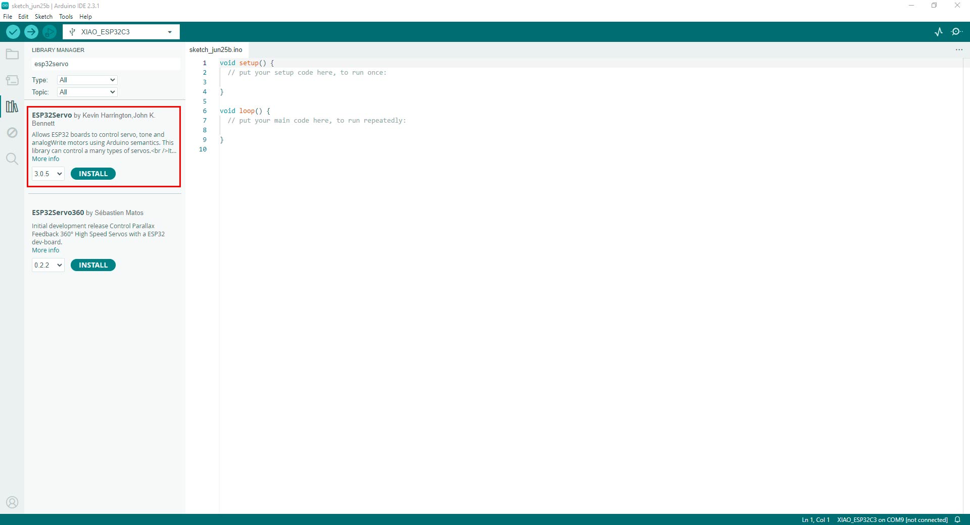
Installing PubSubClient and ESP32Servo libraries in Arduino IDE
Then, I programmed the new PCB that I generated (hereby referred to as PCB1) so that pressing the switch activates the output connected to the Fab&Plant PCB (hereby referred to as PCB2). I used this code -inspired by my colleague Hans Moncca- in the Arduino IDE:
//Fab Academy 2024 - Fab Lab Peru - Maria Angela Mejia
//Code for PCB1 (with XIAO ESP32-C3)

#include < WiFi.h>
#include < PubSubClient.h>

const char* ssid = "YourNetworkName";      //Write the network name you will be connected to
const char* password = "NewtworkPassword"; //Write the network password you will be connected to
const char* mqtt_server = "broker.emqx.io";

const char* topic = "w13";                 // Topic in MQTTX

const int switchPin = D9;                  // Switch Pin

WiFiClient espClient;
PubSubClient client(espClient);

int lastSwitchState = HIGH;                // Previous switch state

void setup() {
  Serial.begin(115200);
  pinMode(switchPin, INPUT_PULLUP);
  setup_wifi();
  client.setServer(mqtt_server, 1883);
}

void setup_wifi() {
  delay(10);
  Serial.println();
  Serial.print("Connecting to ");
  Serial.println(ssid);

  WiFi.begin(ssid, password);

  while (WiFi.status() != WL_CONNECTED) {
  delay(500);
  Serial.print(".");
}

  Serial.println("");
  Serial.println("WiFi connected");
  Serial.println("IP Address: ");
  Serial.println(WiFi.localIP());
}

void reconnect() {
  while (!client.connected()) {
  Serial.print("Connecting to MQTT server...");
  if (client.connect("switchClient")) {
  Serial.println("Connected");
  } else {
  Serial.print("failed, rc=");
  Serial.print(client.state());
  Serial.println(" trying again in 5 seconds");
  delay(5000);
    }
  }
}

void loop() {
  if (!client.connected()) {
  reconnect();
  }
  client.loop();

  int switchState = digitalRead(switchPin);
  if (switchState != lastSwitchState) {    // If there's a change in switch state
  if (switchState == LOW) {
  client.publish(topic, "a");
  Serial.println("Switch pressed");
} else {
  client.publish(topic, "b");
  Serial.println("Switch released");
  }
  lastSwitchState = switchState;
}

  delay(100); // Small delay to avoid switch bounce
}
Code in Arduino IDE for PCB1 with switch
Later, I programmed PCB2 and tested two outputs. First, I conducted an exercise with an LED strip using the following code in the Arduino IDE:
//Fab Academy 2024 - Fab Lab Peru - Maria Angela Mejia
//Code for PCB2 (XIAO ESP32-C3)

#include < WiFi.h>
#include < PubSubClient.h>

const char* ssid = "YourNetworkName";      //Write the network name you will be connected to
const char* password = "NewtworkPassword"; //Write the network password you will be connected to
const char* mqtt_server = "broker.emqx.io";

const char* topic = "w13";                 // Topic in MQTTX: should be the same as the publisher

#define LED_PIN D0                         // D0 pin

WiFiClient espClient;
PubSubClient client(espClient);

void setup() {
  Serial.begin(115200);
  pinMode(LED_PIN, OUTPUT);                // Initialize LED pin as output
  setup_wifi();
  client.setServer(mqtt_server, 1883);
  client.setCallback(callback);
}

void setup_wifi() {
  delay(10);
  Serial.println();
  Serial.print("Connecting to ");
  Serial.println(ssid);

  WiFi.begin(ssid, password);

  while (WiFi.status() != WL_CONNECTED) {
    delay(500);
    Serial.print(".");
  }

  Serial.println("");
  Serial.println("WiFi connected");
  Serial.println("IP Address: ");
  Serial.println(WiFi.localIP());
}

void callback(char* topic, byte* payload, unsigned int length) {
  String message = "";
  for (unsigned int i = 0; i < length; i++) {
    message += (char)payload[i];
  }
  Serial.print("Message received from topic ");
  Serial.print(topic);
  Serial.print(": ");
  Serial.println(message);

  if (message == "a") {
    digitalWrite(LED_PIN, HIGH);          // Turn LED on
  } else {
    digitalWrite(LED_PIN, LOW);           // Turn LED off
  }
}

void reconnect() {
  while (!client.connected()) {
    Serial.print("Connecting to MQTT server...");
    if (client.connect("ledClient")) {
      Serial.println("Connected");
      client.subscribe(topic);
    } else {
      Serial.print("Failed, rc=");
      Serial.print(client.state());
      Serial.println(" trying again in 5 seconds");
      delay(5000);
    }
  }
}

void loop() {
  if (!client.connected()) {
    reconnect();
  }
  client.loop();
}
Code in Arduino IDE for PCB2 with LED strip
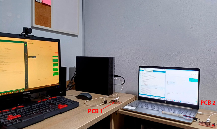
PCB 1 with switch and PCB 2 with LED strip
Later, I conducted the exercise with a servo using the following code in the Arduino IDE:
//Fab Academy 2024 - Fab Lab Peru - Maria Angela Mejia
//Code for PCB2 (XIAO ESP32-C3)

#include < WiFi.h>
#include < PubSubClient.h>
#include < ESP32Servo.h>

const char* ssid = "YourNetworkName";      //Write the network name you will be connected to
const char* password = "NewtworkPassword"; //Write the network password you will be connected to
const char* mqtt_server = "broker.emqx.io";

const char* topic = "w13";                 // Topic in MQTTX: should be the same as the publisher

#define SERVO_PIN D0  // D0 pin

WiFiClient espClient;
PubSubClient client(espClient);
Servo myServo; // create servo object to control a servo

void setup() {
  Serial.begin(115200);
  myServo.attach(SERVO_PIN); // attaches the servo on pin D0 to the servo object
  setup_wifi();
  client.setServer(mqtt_server, 1883);
  client.setCallback(callback);
}

void setup_wifi() {
  delay(10);
  Serial.println();
  Serial.print("Connecting to ");
  Serial.println(ssid);

  WiFi.begin(ssid, password);

  while (WiFi.status() != WL_CONNECTED) {
    delay(500);
    Serial.print(".");
  }

  Serial.println("");
  Serial.println("WiFi connected");
  Serial.println("IP Address: ");
  Serial.println(WiFi.localIP());
}

void callback(char* topic, byte* payload, unsigned int length) {
  String message = "";
  for (unsigned int i = 0; i < length; i++) {
    message += (char)payload[i];
  }
  Serial.print("Message received from topic ");
  Serial.print(topic);
  Serial.print(": ");
  Serial.println(message);

  if (message == "a") {
    myServo.write(0); // rotate the servo to 0 degrees
  } else {
    myServo.write(90); // rotate the servo to 90 degrees
  }
}

void reconnect() {
  while (!client.connected()) {
    Serial.print("Connecting to MQTT server...");
    if (client.connect("servoClient")) {
      Serial.println("Connected");
      client.subscribe(topic);
    } else {
      Serial.print("Failed, rc=");
      Serial.print(client.state());
      Serial.println(" trying again in 5 seconds");
      delay(5000);
    }
  }
}

void loop() {
  if (!client.connected()) {
    reconnect();
  }
  client.loop();
}
Code in Arduino IDE for PCB2 with servo
PCB 1 with switch and PCB 2 with LED strip
Conclusions
- Working with a microcontroller that has Wi-Fi represented a greater difficulty than previous work with other microcontrollers that did not have this feature. Based on my experience this week, I needed to use the reset and boot buttons constantly to get the programming to load or the microcontroller to be recognized by the platform.
- The network to which the microcontroller connects is vital. In my case, I had a lot of problems connecting my microcontroller. Of the 5 networks I tried, only one was able to work well.
- Of the tools used, MQTTX was the most successful in generating connections with the XIAO ESP32-C3. MQTTX is a desktop client application designed to interact with MQTT brokers. It should not be confused with MQTT, which is the protocol used for lightweight messaging in IoT applications. Essentially, MQTTX utilizes the MQTT protocol to facilitate and manage communications between devices and brokers.
- Working with Arduino IoT Cloud requires additional plugins and files that can cause conflicts in the code. Other platforms avoid this, such as ThingSpeak.
- To finish this task I thank my fellow students and tutors, especially Roberto Delgado and Ulises Gordillo for the guidance in this process, Silvana Espinoza and Ronal Vilca for helping me with the use of IoT platforms and valuable tips on connecting my microcontroller.