Final Project
For my final project I wanted to work on a product that incorporates concepts of landscaping, interior design and decoration that could be accessible, sustainable and interactive and responds to the user's needs in terms of connection with nature in urban environments.
You can explore more about the design of Fab&Plant here.
Fab&Plant Q&A
- What Fab&Plant does?
- Who's done what beforehand?
- What did I design?
- What materials and components were used?
- Where did they come from?
- How much did they cost?
- What parts and systems were made?
- What processes were used?
- What questions were answered?
- What worked? What didn't?
- How was it evaluated?
- What are the implications?
What Fab&Plant does?
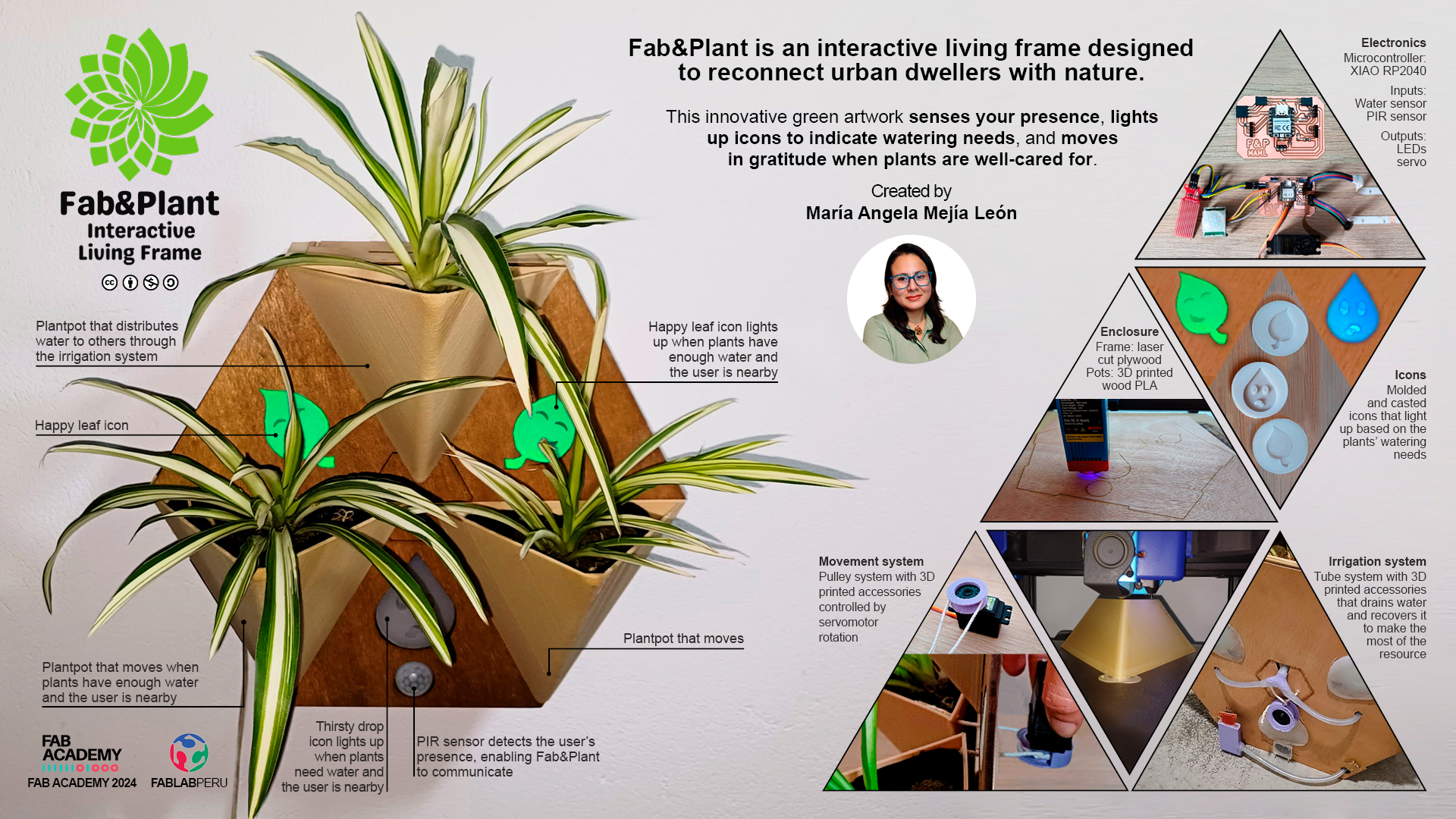
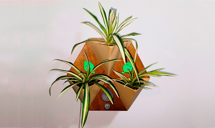
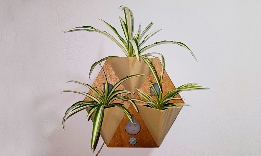
Fab&Plant is an interactive living frame designed to reconnect urban dwellers with nature. This innovative green artwork senses your presence, lights up icons to indicate watering needs, and moves in gratitude when plants are well-cared for. Its efficient water use and modular design make it both eco-friendly and versatile, enhancing a living space with vibrant, responsive greenery.
Ecological impact: Fab&Plant is not merely a decoration; it is an ecological statement. In a world racing against time to combat climate change, my project offers the possibility of having plants in small places. It can be hung on walls or placed on horizontal surfaces, providing a solution to the scarcity of green areas.
Interactive experience: But here is what sets Fab&Plant apart -it is not just a static green frame- it is an interactive masterpiece. As you approach, the frame senses your presence and comes alive with lights and movement.
User-Friendly Experience: Plant care can be challenging for citizens living in congested and noisy cities. Daily tasks often distract from the care and enjoyment of having plants at home. Fab&Plant uses fun, illuminated icons to communicate the plants' watering needs when the system detects the user's presence. When the plants need water, a thirsty drop icon lights up. When you manually irrigate the plants, two happy leaf icons light up, and you will see the gentle movement of the plants as a thank you.
Fab&Plant is not just a product; it is a lifestyle. It is a step towards harmonizing urban living with nature. Join us in making cities greener, more interactive, and delightfully sustainable. Let's redefine urban living with Fab&Plant, the interactive living frame.
Who's Done What Beforehand?
For inspiration and guidance, I reviewed Fab Academy final projects from the past few years.
2023
| Author | Project title | Project video |
|---|---|---|
| Daniel Collins | Moss Wheel | Link |
| Sibin K S | Gropod | Link |
| Ekaterina Kormilitsyna | Symbiotic Devices | Link |
| Ryan Kim | Rotary Hydroponics Garden | Link |
| Lisa Schilling | Selfwatering Flowerpot | Link |
2022
| Author | Project title | Project video |
|---|---|---|
| Pablo Pastor García | Smartpot | Link |
| Paola Zanchetta Muñoz | Fab, Meditation and Plants | Link |
| Juan Carlos Cristaldo | Shadowhouse | Link |
| Rachelle DeCoste | Demeter`s Garden | Link |
| Lakshmi | Selfwatering Pot | Link |
| John Story | Growing Microgreens | Link |
2021
| Author | Project title | Project video |
|---|---|---|
| Ismael Larrea Bravo | Seedling Nursery | Link |
| Jeffery Naranjo | Sustainable Bus Stop | Link |
2019
| Author | Project title | Project video |
|---|---|---|
| Nagi Abdelnour | Automated Indoor Hanging Garden | Link |
These references helped me understand the objective of the final project, guided me to solutions that could be used to solve similar conditions in my project, and inspired me to develop my final project.
What Did I Design?
Frame: The case for holding everything together is created using 2D and 3D design, as well as additive and subtractive fabrication processes. You can explore more about the design of Fab&Plant here.
Fab&Plant: the interactive living frame
Fab&Plant 3D view
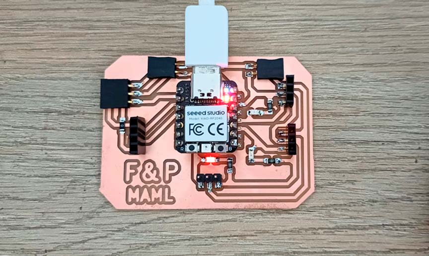
Electronics: The Fab&Plant PCB for the system to work.
Fab&Plant PCB
Programming: Programming the XIAO RP2040 in Fab&Plant PCB.
//Fab Academy 2024 - Fab Lab Peru - Maria Angela Mejia
//Code for Fab&Plant PCB with a XIAO RP2040

#include < Servo.h>

#define WATER_SENSOR A0
#define PIR_SENSOR D1
#define BLUE_LED D9
#define GREEN_LED D10
#define SERVO_PIN A3

Servo servoMotor;

void setup() {
pinMode(WATER_SENSOR, INPUT);
pinMode(PIR_SENSOR, INPUT);
pinMode(BLUE_LED, OUTPUT);
pinMode(GREEN_LED, OUTPUT);

servoMotor.attach(SERVO_PIN);

//LED strips are initially turned off
digitalWrite(BLUE_LED, HIGH);
digitalWrite(GREEN_LED, HIGH);
}

void loop() {
// Read sensors
int humidityValue = analogRead(WATER_SENSOR);
int pirState = digitalRead(PIR_SENSOR);

// If humidity is less than 840 and motion is detected, turn on blue LED
if (humidityValue < 840 && pirState == HIGH) {
digitalWrite(BLUE_LED, LOW);
digitalWrite(GREEN_LED, HIGH);
// Ensure servo motor is off
servoMotor.write(0);
}
// If humidity is 840 or higher and motion is detected, turn on green LED
else if (humidityValue >= 840 && pirState == HIGH) {
digitalWrite(BLUE_LED, HIGH);
digitalWrite(GREEN_LED, LOW);
// Rotate servo motor if humidity is 840 or higher
servoMotor.write(0);   // Move the servo to 0 degrees
delay(200);           // Wait for less than a second
servoMotor.write(90);  // Move the servo to 90 degrees
delay(200);           // Wait for less than a second
servoMotor.write(180); // Move the servo to 180 degrees
delay(200);           // Wait for less than a second
servoMotor.write(90);  // Move the servo back to 90 degrees
delay(200);           // Wait for less than a second
}
// If no motion is detected, turn off both LEDs and servo motor
else {
digitalWrite(BLUE_LED, HIGH);
digitalWrite(GREEN_LED, HIGH);
servoMotor.write(0);
  }
}
Fab&Plant PCB code in Arduino IDE
System: The mechanism for cultivating plants and indicating their watering needs.
Everything designed for my final project was developed through a process with various iterations, which I detail in the Design section of this page.
What materials and components were used?
Frame:
- Wood PLA filament
- PLA filament
- 3mm plywood
- 4mm cardboard
- Felt fabric
- Silicone rubber
- Screws
- Glue
Electronics:
- XIAO RP2040 (1 unit)
- SMD LED (3 units)
- 0K ohm resistor (2 units)
- 1K ohm resistor (3 units)
- Several pin headers
- Servo motor (1 unit)
- Green LED strip (1 unit)
- Blue LED strip (1 unit)
- PIR sensor (1 unit)
- Water sensor (1 unit)
Where did they come from?
The frame materials came from local suppliers; the Wood PLA filament from SUNLU; electronic items from Paruro Market, and the XIAO RP2040 from Digikey.
How much did they cost?
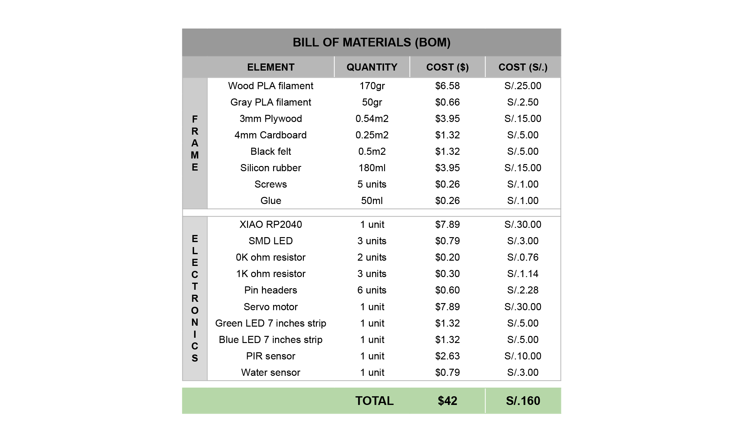
Fab&Plant BOM
What parts and systems were made?
I made the frame, electronics, programming and the mechanism for cultivating plants and indicating their watering needs.
What processes were used?
- Computer aided design
- Laser cutting
- 3D printing
- Molding and casting
- Lithophane
- Electronics design
- PCB milling
- Soldering, testing, debugging
- Embedded programming
- Assembly
- Iteration
What questions were answered?
- Does Fab&Plant communicate the plants watering need well? Some tests were conducted with people close to me, and Fab&Plant effectively communicated the plants' watering needs.
- How long does it take before Fab&Plant needs watering again? Fab&Plant was used throughout the month of June (winter in Lima, Peru) and needed to be watered manually every week.
- What is the maximum amount of water the system requires? The system requires a maximum of 100ml of water for each manual watering.
What worked? What didn't?
In the process of creating this product, the functions I initially envisioned changed. In the end, they all worked, though not in the way I originally imagined.
What I would like to improve is the movement of the pots. Initially, all three pots were supposed to move. I haven't managed to get the top pot to move yet, so I plan to study and test that aspect of my final project more thoroughly.
How will it be evaluated?
The objective of Fab&Plant is to reconnect ordinary citizens in urban environments with nature. Thanks to its functionality, I believe I have achieved this goal.
What are the implications?
My final project is still a prototype that I plan to continue working on after the Fab Academy ends. Once the final product is achieved, I aim for it to become an accessible, sustainable kit for use in homes, fostering reconnection between people and nature in urban environments.
I would also like similar projects, or those based on mine, to be replicated within the Fab Lab network. This could help generate and strengthen a community focused on creating sustainable products and solutions using digital fabrication tools.
Concept
Fab&Plant is an interactive living frame designed to reconnect urban dwellers with nature. This innovative green artwork senses your presence, lights up icons to indicate watering needs, and moves in gratitude when plants are well-cared for. Its efficient water use and modular design make it both eco-friendly and versatile, enhancing a living space with vibrant, responsive greenery.
Fab&Plant
Schedule
I worked on my project based on the concept of Spiral Development (Phanuwit Rico Kanthatham's concept). The first spiral focused on creating the concept and initial ideas, exploring the movement and actions I wanted to generate through inputs and outputs. This resulted in a preliminary model. In the second spiral, I worked on the electronics and project programming, producing the board and initial programming tests for each part individually. The third spiral involved programming the entire product and assembling the first version of Fab&Plant. Finally, in the fourth spiral, I improved the assembly by integrating the system and tested the final prototype of my project.
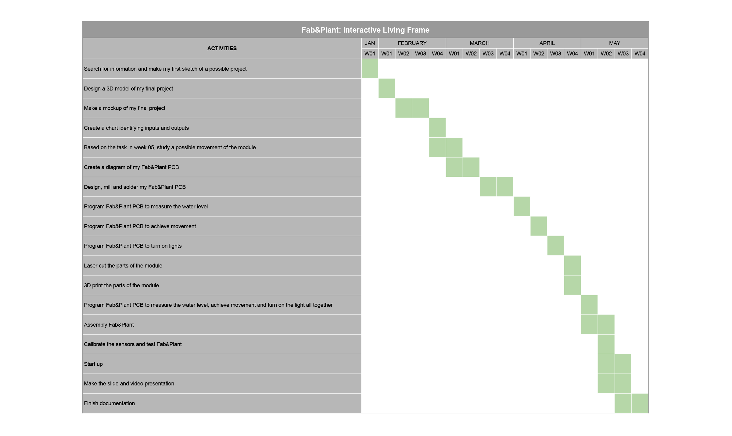
Fab&Plant Schedule
Design
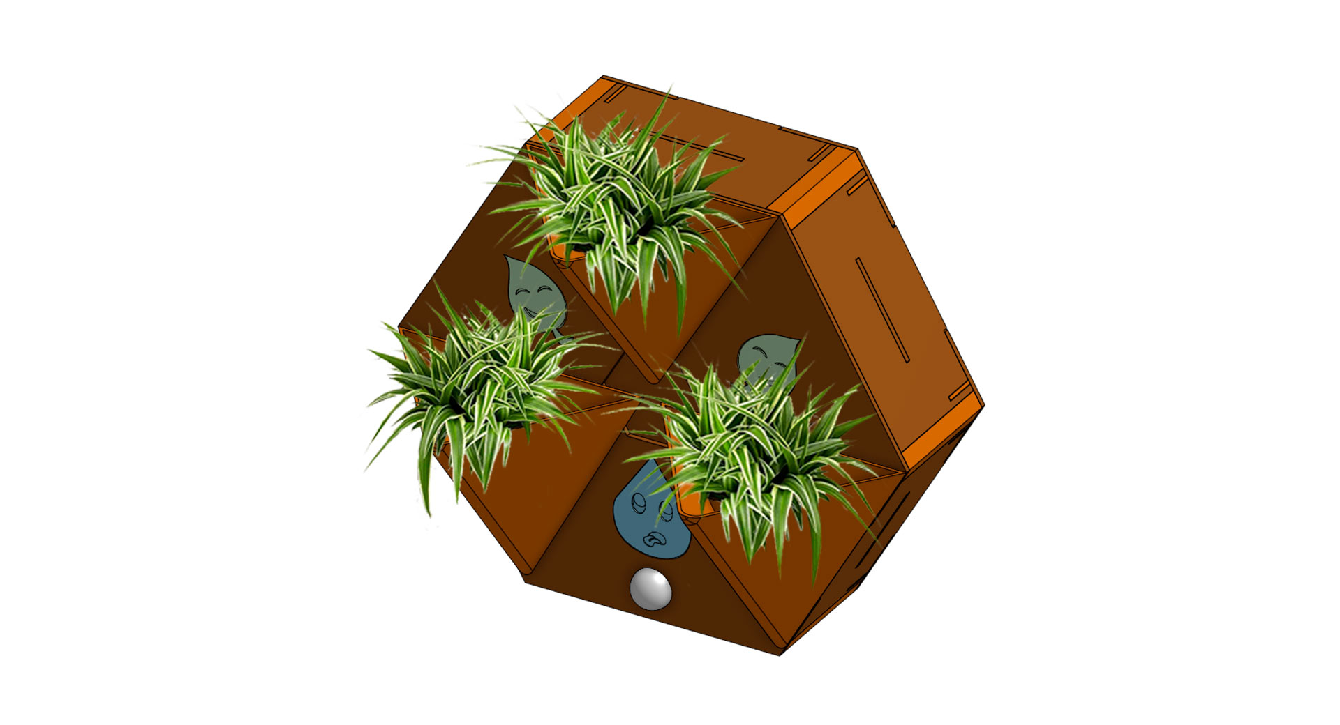
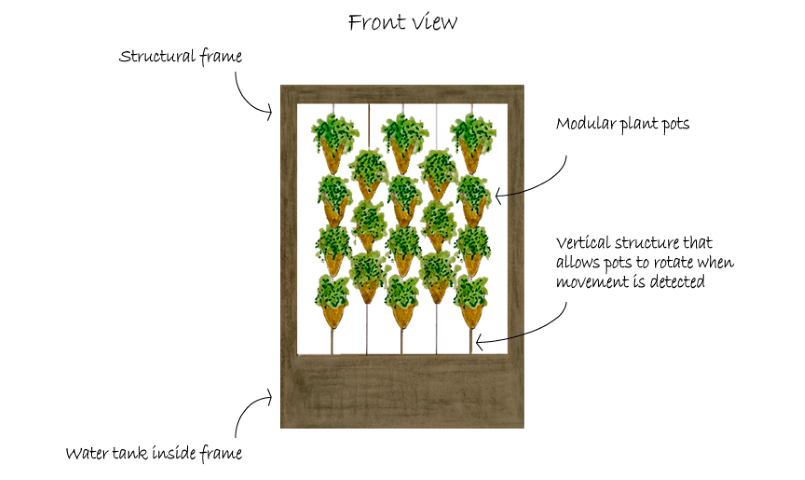
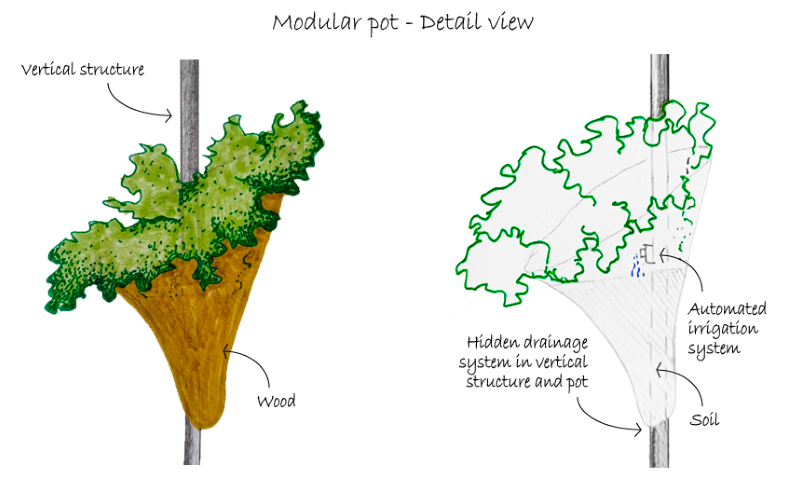
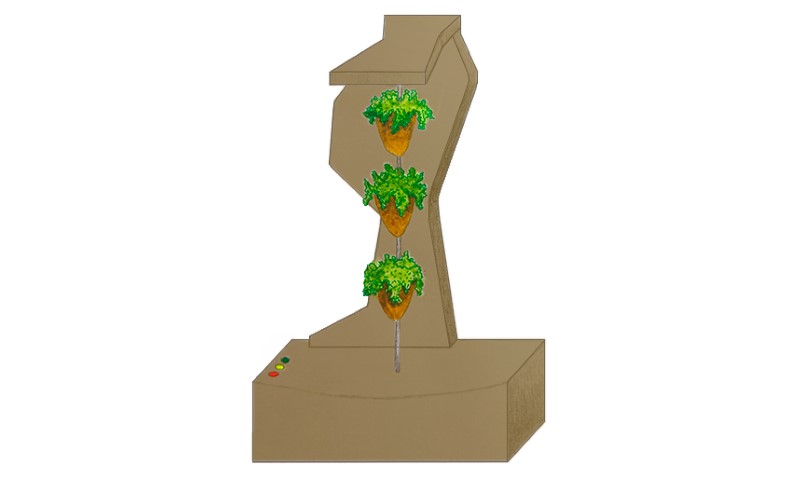
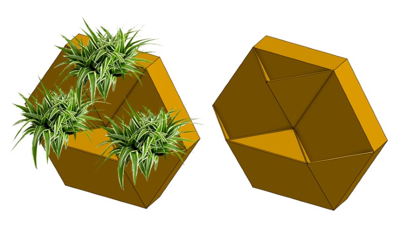
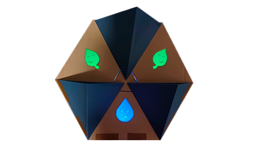
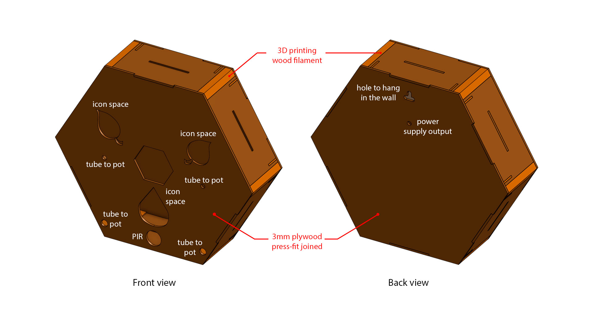
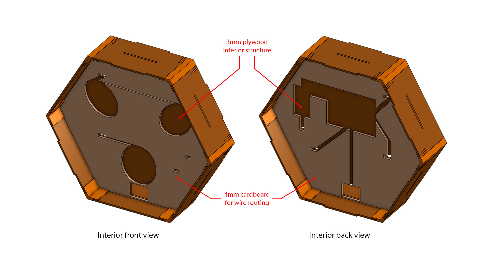
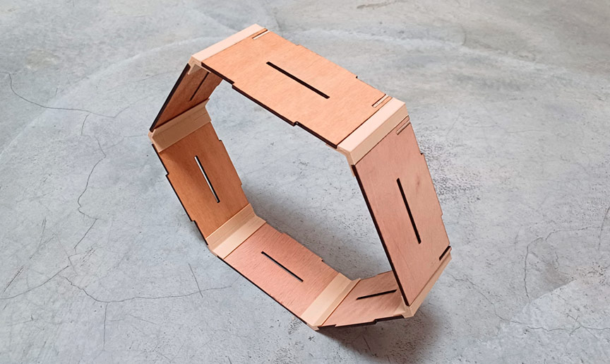
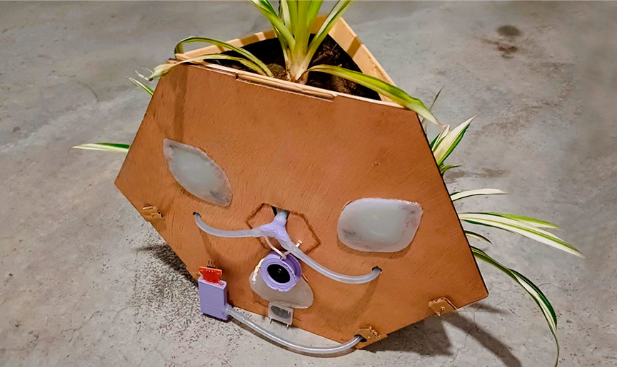
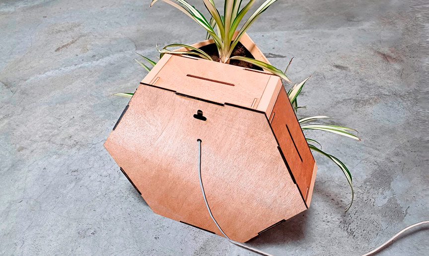
Fab&Plant features a hexagonal shape inscribed in a 30cm diameter circle, constructed from three layers of 3mm laser-cut plywood assembled with press-fit (middle layer) and glue (external layers). The outer layers (front and back) form the enclosure, while the inner layer houses the technological core and structure. This design allows the system to function independently or as part of a larger vertical garden by combining multiple living frames. The front outer layer includes three planters and icons that illuminate based on the system's water level detection. The power cable is located at the back of the living frame for easy access and minimal visual intrusion. Inside, the PCB and electronic components are housed, including a water sensor level and PIR sensor as inputs, and LED strips and a servo motor as outputs.
Design Evolution
Initially, I focused on the concept of a vertical garden. The product evolved to find a shape that could adapt to different walls and environments, both indoors and outdoors. This led me to the hexagonal shape, creating a living frame that operates autonomously.
Design evolution
After designing various versions of Fab&Plant models, I created preliminary mockups to test the product in a real environment.
Fab&Plant first mockups
Breathing Module
In week 5, I created a chainmail that inspired me for making the movement in my final project module.
Final Design
The goal of Fab&Plant is to enable users to reconnect with a natural environment by caring for their plants, with a product that interacts through lights and movement, thereby enhancing their quality of life. After different iterations, the final version of my Fab Academy project is the following:
Fab&Plant final design
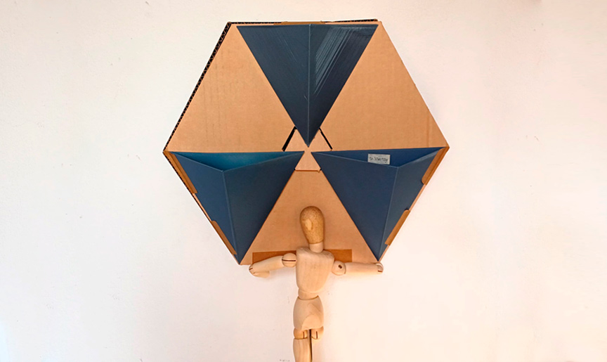
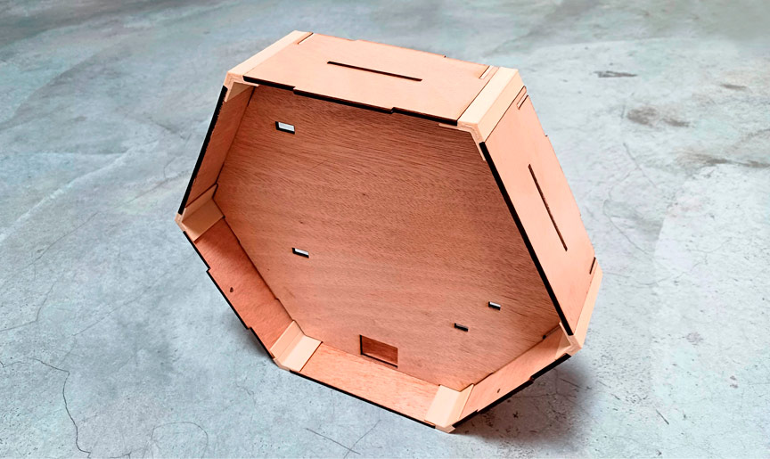
Laser Cutted Parts
The pieces of the frame (the container of the entire system) were crafted from laser-cut 3mm plywood, with Bagheera, my cat, supervising the entire process.
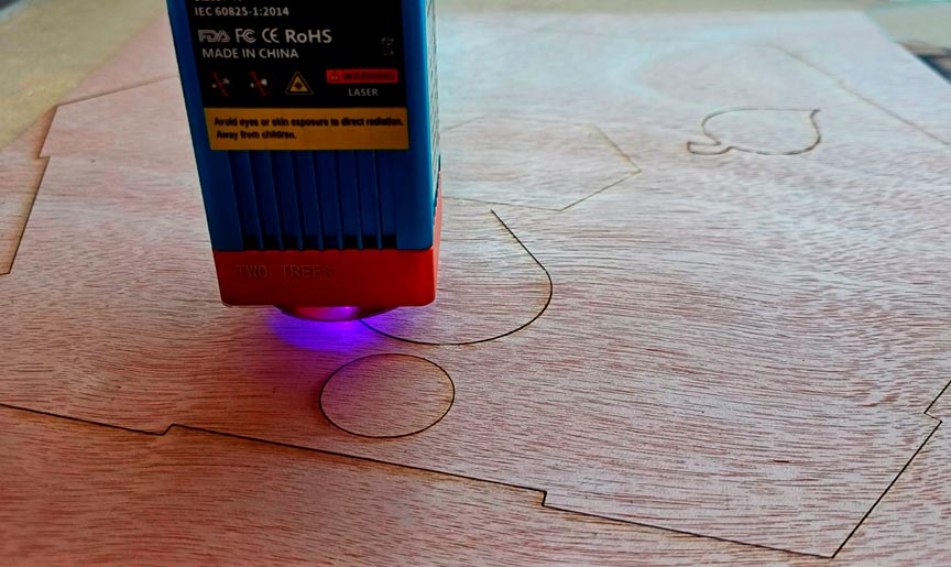
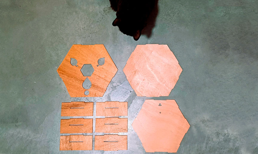
Fab&Plant laser cutted frame parts
3D Printed Parts
I 3D printed the pots -for the plants- and columns -that defined and connected the edges of the frame- using wood PLA filament.
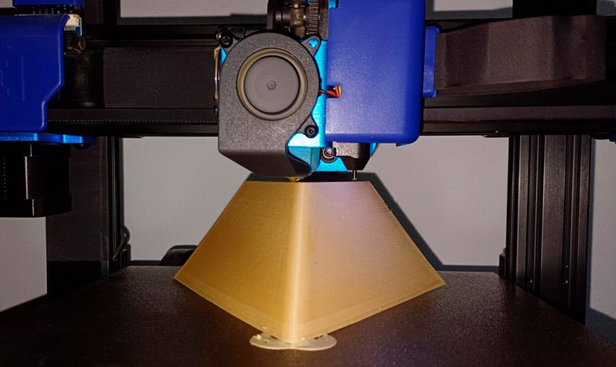
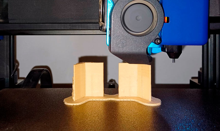
Fab&Plant 3D printed plantpots and frame columns
I also 3D printed accessories for the internal irrigation system, holders for the board and the servomotor, and a component on the servo propeller designed to move the pots, all using gray PLA.
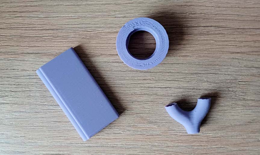
Fab&Plant 3D printed system accesories
Molded and Casted Parts
I created the icons used to communicate the watering needs of the plants using silicone rubber during week 12.
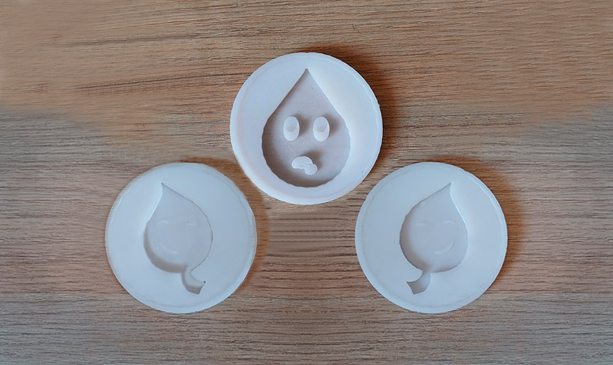
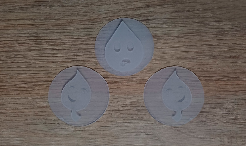
Icons silicone molds and casted pieces
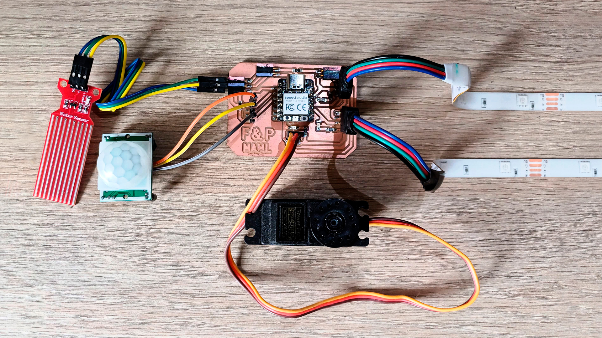
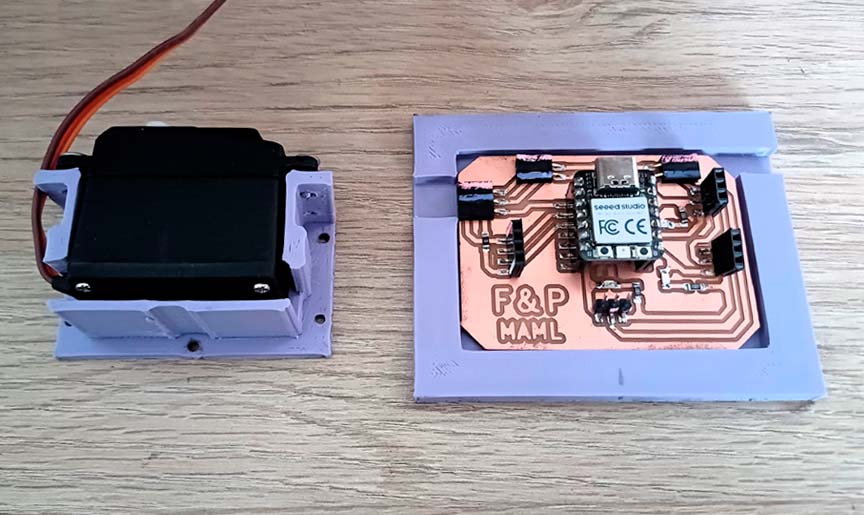
Electronics
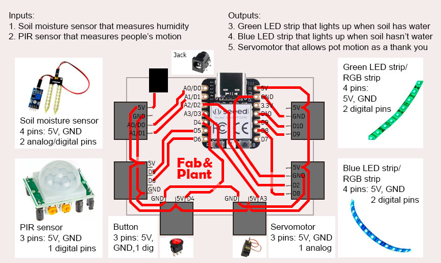
Inputs and Outputs
| Input | Output |
|---|---|
| Water level sensor measures the level of water in the system | If motion is detected, and if water level is less than 840, the blue LED turns on lighting the thirsty drop icon | If motion is detected, and if water level is 840 or more, the green LED turns on lighting the happy leaf icons, and servomotor allow movement of the pots |
| PIR sensor detects motion around the module | If motion is detected, and according water level, the LEDs turn on and servomotor rotates its blades to allow pots with plants movement |

Input/output scheme
Fab&Plant PCB diagram
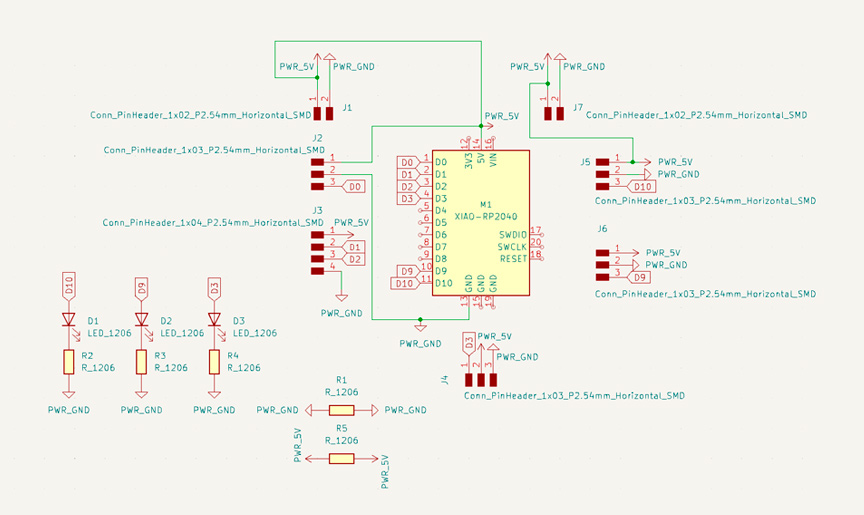
Fab&Plant PCB schematics
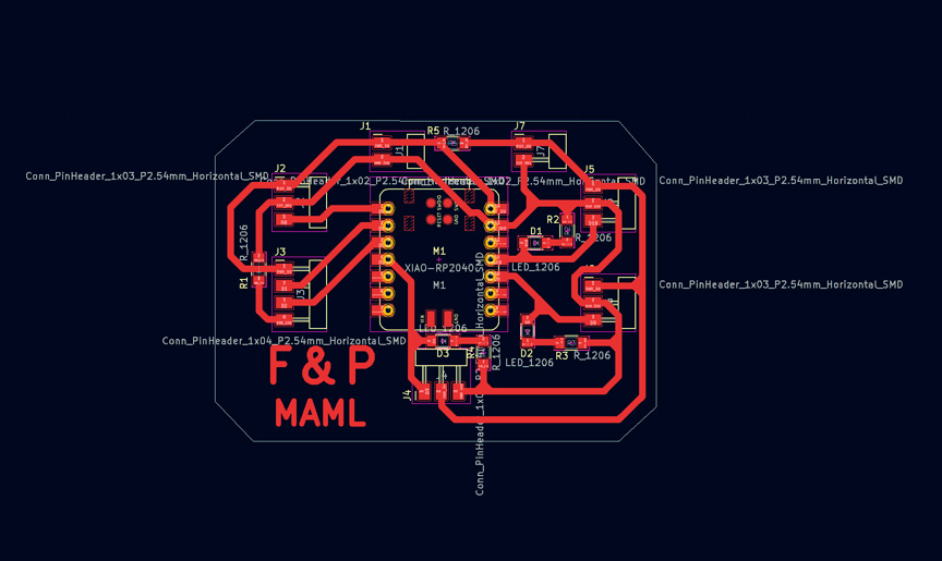
Fab&Plant PCB traces
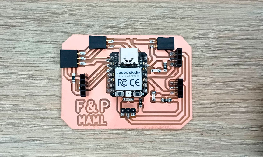
Fab&Plant PCB
Fab&Plant PCB with inputs and outputs
Programming
I programmed the Seeed XIAO RP2040 microcontroller in Arduino IDE with a water level sensor and a PIR sensor as inputs, and a servomotor and two LED strips (green and blue) as outputs.
//Fab Academy 2024 - Fab Lab Peru - Maria Angela Mejia
//Code for Fab&Plant PCB with a XIAO RP2040

#include < Servo.h>

#define WATER_SENSOR A0
#define PIR_SENSOR D1
#define BLUE_LED D9
#define GREEN_LED D10
#define SERVO_PIN A3

Servo servoMotor;

void setup() {
pinMode(WATER_SENSOR, INPUT);
pinMode(PIR_SENSOR, INPUT);
pinMode(BLUE_LED, OUTPUT);
pinMode(GREEN_LED, OUTPUT);

servoMotor.attach(SERVO_PIN);

//LED strips are initially turned off
digitalWrite(BLUE_LED, HIGH);
digitalWrite(GREEN_LED, HIGH);
}

void loop() {
// Read sensors
int humidityValue = analogRead(WATER_SENSOR);
int pirState = digitalRead(PIR_SENSOR);

// If humidity is less than 840 and motion is detected, turn on blue LED
if (humidityValue < 840 && pirState == HIGH) {
digitalWrite(BLUE_LED, LOW);
digitalWrite(GREEN_LED, HIGH);
// Ensure servo motor is off
servoMotor.write(0);
}
// If humidity is 840 or higher and motion is detected, turn on green LED
else if (humidityValue >= 840 && pirState == HIGH) {
digitalWrite(BLUE_LED, HIGH);
digitalWrite(GREEN_LED, LOW);
// Rotate servo motor if humidity is 840 or higher
servoMotor.write(0);   // Move the servo to 0 degrees
delay(200);           // Wait for less than a second
servoMotor.write(90);  // Move the servo to 90 degrees
delay(200);           // Wait for less than a second
servoMotor.write(180); // Move the servo to 180 degrees
delay(200);           // Wait for less than a second
servoMotor.write(90);  // Move the servo back to 90 degrees
delay(200);           // Wait for less than a second
}
// If no motion is detected, turn off both LEDs and servo motor
else {
digitalWrite(BLUE_LED, HIGH);
digitalWrite(GREEN_LED, HIGH);
servoMotor.write(0);
  }
}
Fab&Plant PCB code in Arduino IDE
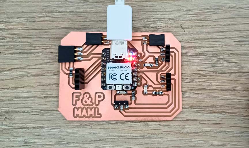
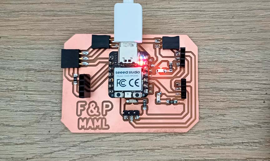
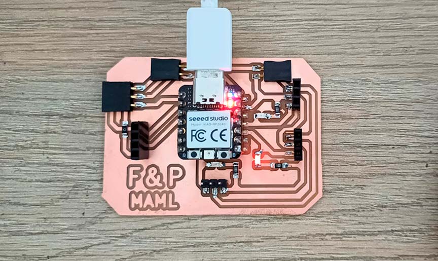
Debugging Fab&Plant PCB
As part of the debugging process, I tested the board, as well as the inputs and outputs, separately.
Testign the Board
//Fab Academy 2024 - Fab Lab Peru - Maria Angela Mejia
//Code for blink LEDs and test the output pins with XIAO RP2040

// Define the pin for the LEDs
const int ledPin1 = D9;
const int ledPin2 = D3;
const int ledPin3 = D10;

// The setup function runs once when you press reset or power the board
void setup() {
  // Initialize digital pins ledPin1, ledPin2, and ledPin3 as outputs
  pinMode(ledPin1, OUTPUT);
  pinMode(ledPin2, OUTPUT);
  pinMode(ledPin3, OUTPUT);
}

// The loop function runs over and over again forever
void loop() {
  {
  digitalWrite(ledPin1, HIGH);       // turn the LED on (HIGH is the voltage level)
  delay(1000);                       // wait for a second
  digitalWrite(ledPin1, LOW);        // turn the LED off by making the voltage LOW
  delay(1000);                       // wait for a second
  } {
  digitalWrite(ledPin2, HIGH);       // turn the LED on (HIGH is the voltage level)
  delay(1000);                       // wait for a second
  digitalWrite(ledPin2, LOW);        // turn the LED off by making the voltage LOW
  delay(1000);                       // wait for a second
  } {  digitalWrite(ledPin3, HIGH);  // turn the LED on (HIGH is the voltage level)
  delay(1000);                       // wait for a second
  digitalWrite(ledPin3, LOW);        // turn the LED off by making the voltage LOW
  delay(1000);                       // wait for a second
  }
}
Code in Arduino IDE for test the LEDs in Fab&Plant board
Debugging Fab&Plant board
Testing the Inputs
The following codes were used in the Arduino IDE to test the water level sensor and the PIR sensor.
//Fab Academy 2024 - Fab Lab Peru - Maria Angela Mejia
//Water sensor code in XIAO RP 2040 in Fab&Plant PCB

// constant
const int sensorPin = A0;

// Function to setup the serial monitor
void setup() {
  // Initialize the serial communication at 9600 baud rate
  Serial.begin(9600);
}

// Function to read the sensor value
void loop() {
  // Read the analog value from the sensor
  int sensorValue = analogRead(sensorPin);

  // Print the sensor value
  Serial.print("Sensor Value: ");
  Serial.print(sensorValue);

  // Delay for 5 seconds before reading again
  delay(5000);
}
Code in Arduino IDE for test water sensor in Fab&Plant PCB
//Fab Academy 2024 - Fab Lab Peru - Maria Angela Mejia
//Code for blink LED when motion is detected by PIR sensor connected to XIAO RP2040

int pirPin = D1;
int ledPin = D3;
int pirValue;

void setup() {
  // put your setup code here, to run once:
  pinMode(ledPin, OUTPUT);
  pinMode(pirPin, INPUT);
  digitalWrite(ledPin, LOW);
}

void loop() {
  // put your main code here, to run repeatedly:
  pirValue = digitalRead(pirPin);
  digitalWrite(ledPin, pirValue);
}
Code in Arduino IDE for test the PIR sensor with LED in Fab&Plant PCB
//Fab Academy 2024 - Fab Lab Peru - Maria Angela Mejia
//Code for PIR sensor (HC-SR501) connected to XIAO RP2040

const int pinPIR = D1;
int pirValue;

void setup() {
  // Start serial communication
  Serial.begin(115200);
  // Configure the PIR sensor pin as input
  pinMode(pinPIR, INPUT);
}

void loop() {
  // Read the state of the PIR sensor
  int pirState = digitalRead(pinPIR);

  // If motion is detected
  if (pirState == HIGH) {
	// Print "movement" message on the serial port
	Serial.println("Movement detected");
  } else {
	// Print "off" message on the serial port
	Serial.println("No movement detected");
  }

  // Wait for a brief period before reading again
delay(1000);
}
Code in Arduino IDE for test the PIR sensor in Fab&Plant PCB with serial monitor
Testing the Outputs
The following codes were used in the Arduino IDE to test the servomotor and the LED strips.
//Fab Academy 2024 - Fab Lab Peru - Maria Angela Mejia
//Code for servomotor connected to XIAO RP2040

#include < Servo.h>

#define SERVO_PIN A3

Servo servoMotor;  // Create a servo object to control a servo

void setup() {
  servoMotor.attach(SERVO_PIN);  // Attaches the servo on pin A3 to the servo object
}

void loop() {
  // Move the servo to different positions
  servoMotor.write(0);    // Move the servo to 0 degrees
  delay(1000);            // Wait for 1 second
  servoMotor.write(90);   // Move the servo to 90 degrees
  delay(1000);            // Wait for 1 second
  servoMotor.write(180);  // Move the servo to 180 degrees
  delay(1000);            // Wait for 1 second
}
Code in Arduino IDE for test servomotor in Fab&Plant PCB
//Fab Academy 2024 - Fab Lab Peru - Maria Angela Mejia
//Code for smooth transition of LED strips using PWM with XIAO RP2040

// Define the pin for the LED strips
const int ledPin1 = D9;   // Define the pin for blue LED strip
const int ledPin2 = D10;  // Define the pin for green LED strip

// The setup function runs once when you press reset or power the board
void setup() {
  // Initialize digital pins ledPin1 and ledPin2 as outputs
  pinMode(ledPin1, OUTPUT);
  pinMode(ledPin2, OUTPUT);
}

// The loop function runs over and over again forever
void loop() {
  // Gradually increase brightness
  for (int brightness = 0; brightness <= 255; brightness++) {
	analogWrite(ledPin1, brightness);
	analogWrite(ledPin2, brightness);
	delay(15); // Adjust delay for desired transition speed
  }

  // Gradually decrease brightness
  for (int brightness = 255; brightness >= 0; brightness--) {
	analogWrite(ledPin1, brightness);
	analogWrite(ledPin2, brightness);
	delay(15); // Adjust delay for desired transition speed
  }
}
Code in Arduino IDE for test LED strips in Fab&Plant PCB
By testing each part of the system separately, I ensured that everything was operational as part of the debugging process.
System Integration
I used the frame itself to integrate all parts of my project. In the center towards the rear side is the board, while towards the front (the face of the product where the plants are located) are the inputs and outputs. The frame closes at the back, leaving only the power cable visible. On the front, the frame is covered with the plants, the icons that communicate the plants' needs to the user, and the surface part of the PIR sensor.
Fab&Plant exterior design
Fab&Plant interior design

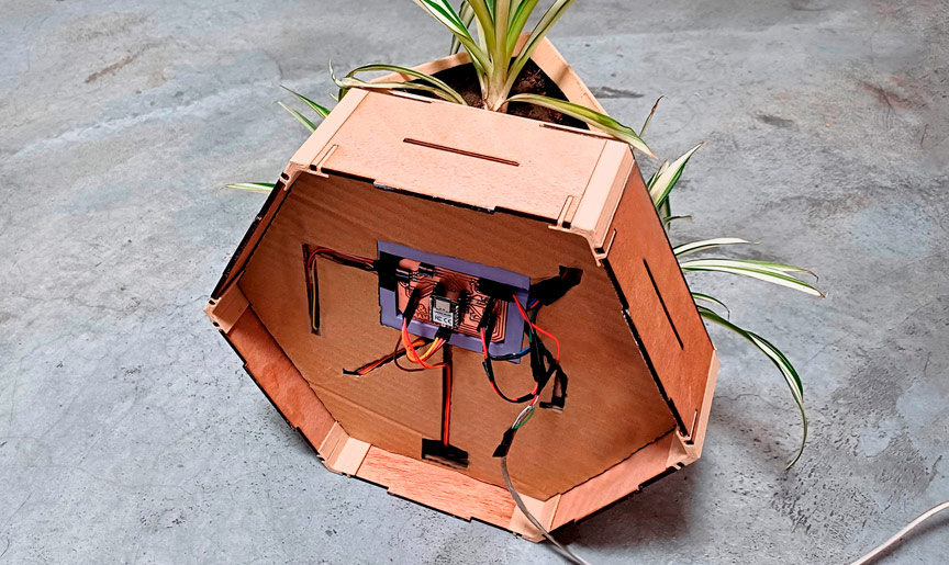
Fab&Plant system integration
Fab&Plant
Special Thanks
The learning and work I accomplished during this program would not have been possible without the wise guidance of Professor Neil Gershenfeld and the entire Fab Academy team, especially to the Open Global Time community. Thank you for creating and constantly updating this incredible program. I also want to thank my tutors for their support and guidance throughout this period. Additionally, I am grateful to my colleagues for their support and camaraderie. It has been a pleasant journey with you. Finally, the support and encouragement of my family during this period were essential. Thank you for everything.
Tutors:
- Benito Juarez
- Vaneza Caycho
- Roberto Delgado
- Ulises Gordillo
- Luis Miguel Rodriguez
- Hayashi Mateo
- Michael Hurtado
- Victor Freundt
Fellow students:
- Silvana Espinoza
- Hans Moncca
- Ronal Vilca
- Christian Loayza
- Maryori Vasquez
- Renson Samaniego
- Wilber Giron
- Jose Rodriguez
- Grace Schwan
- Jesus Lucero
Files
- Fab&Plant design in Onshape
- Fab&Plant design file
- Fab&Plant plywood vertical layers file
- Fab&Plant plywood lateral layers file
- Fab&Plant cardboard interior layers file
- Fab&Plant pots file
- Fab&Plant column file
- Fab&Plant servo accessory file
- Fab&Plant servo support file
- Fab&Plant water sensor container file
- Fab&Plant Y connector file
- Fab&Plant PCB support
- Fab&Plant PCB file
- Fab&Plant PCB traces from MODS file
- Fab&Plant icons molds file