Results: Output Devices
My exploration with output devices this week is important for my final project. Therefore, I focused on testing a servomotor, mini speaker, and RGB LED strip. To test the output devices I used the XIAO RP2040 on the Fab&Plant PCB that I made on week 8.
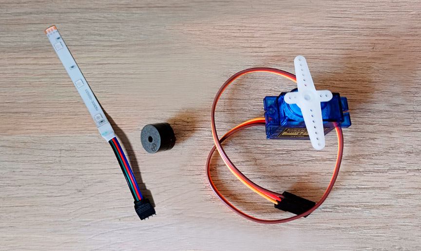
Output devices tested this week
This is the result I got with the servomotor:
#include < Servo.h>

#define SERVO_PIN A0

Servo servoMotor;  // Create a servo object to control a servo

void setup() {
  servoMotor.attach(SERVO_PIN);  // Attaches the servo on pin A0 to the servo object
}

void loop() {
  // Move the servo to different positions
  servoMotor.write(0);    // Move the servo to 0 degrees
  delay(1000);            // Wait for 1 second
  servoMotor.write(90);   // Move the servo to 90 degrees
  delay(1000);            // Wait for 1 second
  servoMotor.write(180);  // Move the servo to 180 degrees
  delay(1000);            // Wait for 1 second
}
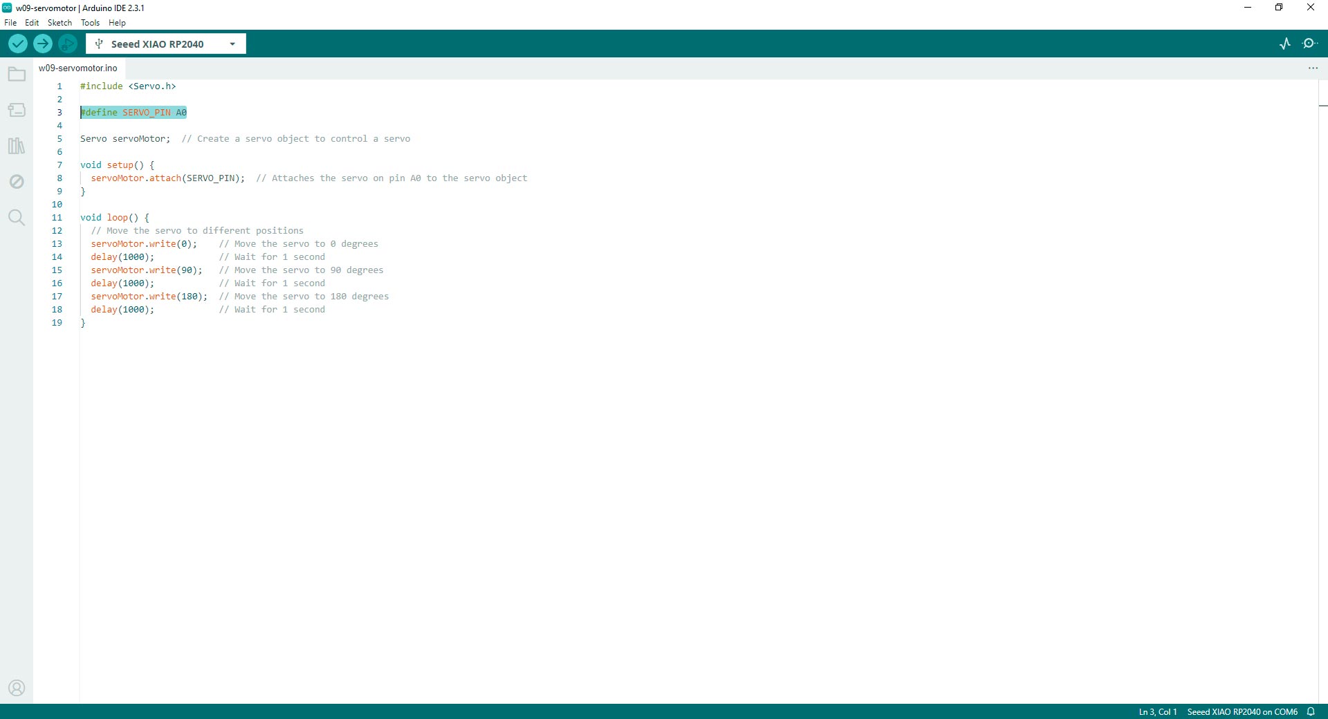
Code in Arduino IDE for programming the microservo in Fab&Plant PCB
This is the Happy Birthday melody I got with the mini speaker:
#define SPEAKER_PIN D0 // D0 pin

void setup() {
  pinMode(SPEAKER_PIN, OUTPUT);
}

void loop() {
  // Play Happy Birthday melody
  playNote(262, 400); // C4
  playNote(262, 400); // C4
  playNote(294, 800); // D4
  playNote(262, 800); // C4
  playNote(349, 800); // F4
  playNote(330, 1600); // E4

  // Second line
  playNote(262, 400); // C4
  playNote(262, 400); // C4
  playNote(294, 800); // D4
  playNote(262, 800); // C4
  playNote(392, 800); // G4
  playNote(349, 1600); // F4

  // Third line
  playNote(262, 400); // C4
  playNote(262, 400); // C4
  playNote(523, 800); // C5
  playNote(440, 800); // A4
  playNote(349, 800); // F4
  playNote(330, 800); // E4
  playNote(294, 800); // D4

  // Fourth line
  playNote(466, 400); // A#4
  playNote(466, 400); // A#4
  playNote(440, 800); // A4
  playNote(349, 800); // F4
  playNote(392, 800); // G4
  playNote(349, 1600); // F4

}

// Function to play a note of a given frequency and duration
void playNote(int frequency, int duration) {
  tone(SPEAKER_PIN, frequency, duration);
  delay(duration + 50); // Add a slight delay between notes for rhythm
}
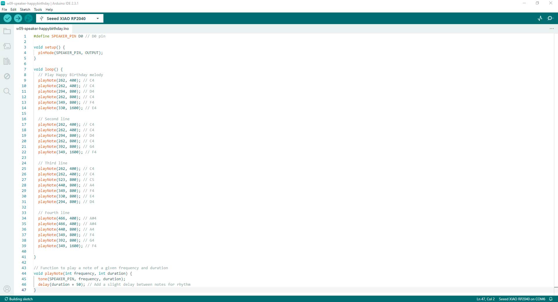
Code in Arduino IDE for programming the mini speaker in Fab&Plant PCB
This is the result I got with the RGB LED strip:
//Fab Academy 2024 - Fab Lab Peru - Maria Angela Mejia
//Code for RGB LED connected to a XIAO RP2040 using ChatGPT generated code

// Pin definitions
const int greenLedPin = D0;  // Pin connected to the green LED

void setup() {
  // Initialize the digital pin as an output.
  pinMode(greenLedPin, OUTPUT);
}

void loop() {
  // Fade in from off to maximum brightness
  for (int brightness = 0; brightness <= 255; brightness++) {
    analogWrite(greenLedPin, brightness);
    delay(10);  // Adjust the delay for the speed of the fade
  }

  // Keep the LED on for a while
  delay(500);

  // Fade out from maximum brightness to off
  for (int brightness = 255; brightness >= 0; brightness--) {
    analogWrite(greenLedPin, brightness);
    delay(10);  // Adjust the delay for the speed of the fade
  }

  // Keep the LED off for a while
  delay(1000);
}
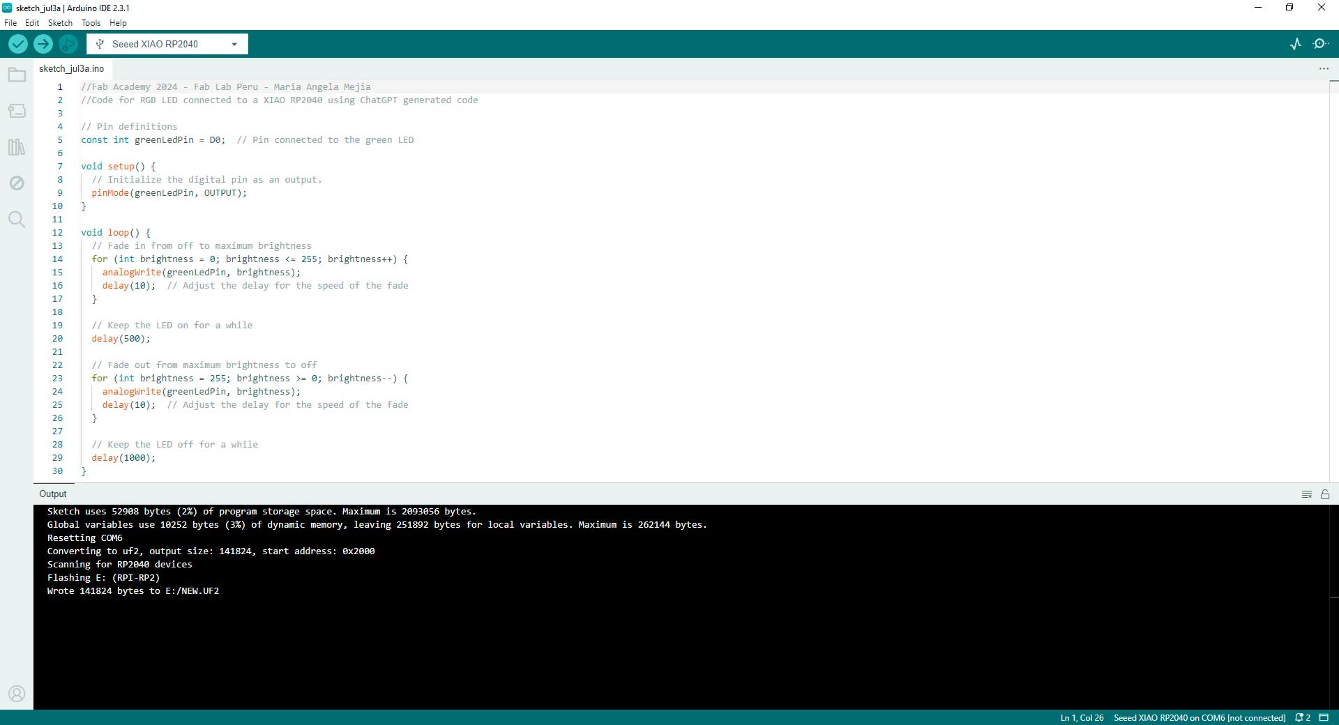
Code in Arduino IDE for programming the RGB LED strip in Fab&Plant PCB
There was very intense work this week and I feel I little bit closer to understand the electronics in my final project.
Group Assignment: Measure Power Consumption
The group assignment page is here.
Individual Assignment: Exploration with Output Devices
An output device is any component or device that receives signals or data from a computer or electronic system and converts them into a human-readable form or a form usable by other systems. Output devices are crucial for displaying information, transmitting data, or controlling other devices based on processed input. Examples include displays (such as monitors, screens, or LEDs), printers, speakers, actuators (such as motors or solenoids), and communication interfaces (such as audio output jacks or network ports). These devices play a vital role in providing feedback, presenting results, or enabling interaction between electronic systems and users or other systems.
Understanding the fundamental workings and activation methods of output devices is essential for effectively integrating them into electronic projects. In this case, I used a servomotor, mini speaker, and a RGB LED strip connected to XIAO RP2040. Since I did not connect inputs, the way of activation will be basically through programming:
- Servomotor:
Working Principle: Receives a Pulse Width Modulation (PWM) signal to determine position. The motor moves the shaft to the desired angle using feedback control.
Activation: Connect the servomotor to a microcontroller, initialize it using a library like Arduino's Servo library, and send PWM signals to control its position. - Mini speaker:
Working Principle: Receives varying electrical voltages to vibrate a diaphragm. The vibrations produce sound waves in the air.
Activation: Connect the speaker to a microcontroller, set an output pin, and send varying voltage levels or use functions like tone() to produce audio frequencies or custom functions such as playNote to play specific musical notes. - RGB LED Strip:
Working Principle: Receives digital signals to adjust power to red, green, and blue LEDs. Each LED emits light according to the signal, creating varied colors and intensities.
Activation: Connect the LED strip, and send color data commands to control LED's color and brightness.
Servomotor
A servomotor is a rotary or linear actuator that allows for precise control of angular or linear position, velocity, and acceleration. It consists of a motor, a control circuit, and a feedback mechanism. Servomotors are commonly used in applications where accurate and controlled movement is required, such as robotics, RC vehicles, industrial automation, and aerospace systems. They can maintain a specific position or move to a desired position based on input signals, making them versatile components in various electromechanical systems.
The SG90 Tower Pro microservomotor, commonly known as the "9g microservo," is a compact and lightweight actuator renowned for its versatility and precision. With its small size of 23mm x 12.2mm x 29mm and lightweight design of approximately 9 grams, it is ideal for applications where space and weight are critical factors. Despite its diminutive stature, the SG90 is capable of exerting considerable torque, typically around 1.5 to 2.5 kg/cm, enabling it to perform a wide range of tasks with ease. Equipped with a feedback control system, it offers accurate and repeatable positioning, making it suitable for tasks requiring precise motion control. The SG90 operates over a standard pulse width modulation (PWM) signal range, typically from 1000µs to 2000µs, allowing for compatibility with various microcontroller platforms. Whether used in robotics, model airplanes, or other mechatronic applications, the SG90 microservomotor stands out for its reliability, compactness, and exceptional performance.
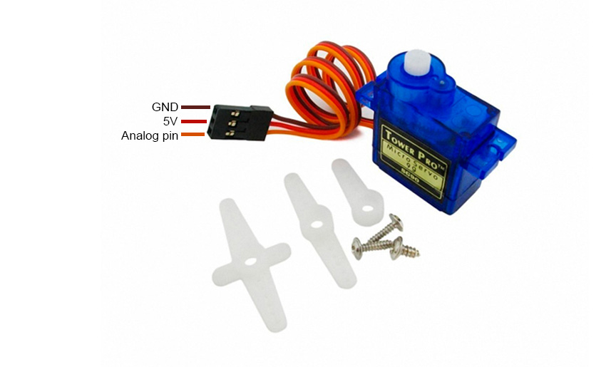
9g microservo
I programmed the servomotor with the XIAO RP2040 on the Fab&Plant PCB that I made in week 8.
#include < Servo.h>

#define SERVO_PIN A0

Servo servoMotor;  // Create a servo object to control a servo

void setup() {
  servoMotor.attach(SERVO_PIN);  // Attaches the servo on pin A0 to the servo object
}

void loop() {
  // Move the servo to different positions
  servoMotor.write(0);    // Move the servo to 0 degrees
  delay(1000);            // Wait for 1 second
  servoMotor.write(90);   // Move the servo to 90 degrees
  delay(1000);            // Wait for 1 second
  servoMotor.write(180);  // Move the servo to 180 degrees
  delay(1000);            // Wait for 1 second
}
Code in Arduino IDE for programming the servomotor in Fab&Plant PCB
For my final project, I will probably use a higher power servomotor.
Mini Speaker
The mini speaker is a compact audio transducer designed for integration into electronic devices and circuits. With a diameter of 12mm, it occupies minimal space, making it suitable for applications where size is a constraint. Operating at a frequency of 2.048kHz, it produces sound output within the audible range, suitable for various audio signaling purposes. Mounted directly onto PCBs, it simplifies assembly and integration into electronic projects. Despite its small size, it offers clear and recognizable sound reproduction, making it useful for alarms, notifications, and other audio playback applications in portable electronics, appliances, and gadgets.
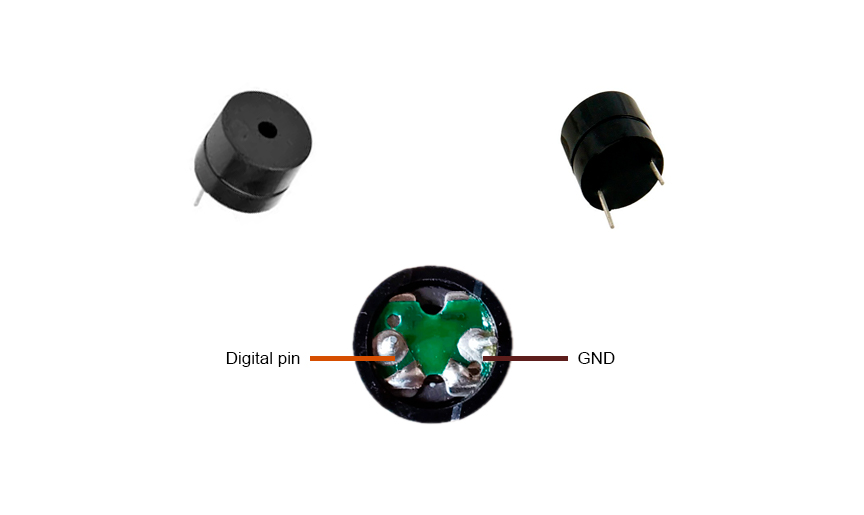
Mini speaker
I programmed the mini speaker with the XIAO RP2040 on the Fab&Plant PCB that I made in week 8 for getting the happy birthday melody.
#define SPEAKER_PIN D0 // D0 pin

void setup() {
  pinMode(SPEAKER_PIN, OUTPUT);
}

void loop() {
  // Play Happy Birthday melody
  playNote(262, 400); // C4
  playNote(262, 400); // C4
  playNote(294, 800); // D4
  playNote(262, 800); // C4
  playNote(349, 800); // F4
  playNote(330, 1600); // E4

  // Second line
  playNote(262, 400); // C4
  playNote(262, 400); // C4
  playNote(294, 800); // D4
  playNote(262, 800); // C4
  playNote(392, 800); // G4
  playNote(349, 1600); // F4

  // Third line
  playNote(262, 400); // C4
  playNote(262, 400); // C4
  playNote(523, 800); // C5
  playNote(440, 800); // A4
  playNote(349, 800); // F4
  playNote(330, 800); // E4
  playNote(294, 800); // D4

  // Fourth line
  playNote(466, 400); // A#4
  playNote(466, 400); // A#4
  playNote(440, 800); // A4
  playNote(349, 800); // F4
  playNote(392, 800); // G4
  playNote(349, 1600); // F4

}

// Function to play a note of a given frequency and duration
void playNote(int frequency, int duration) {
  tone(SPEAKER_PIN, frequency, duration);
  delay(duration + 50); // Add a slight delay between notes for rhythm
}
Code in Arduino IDE for programming the mini speaker in Fab&Plant PCB
RGB LED Strip
An RGB LED strip is a flexible and versatile lighting solution that features a series of Red, Green, and Blue light-emitting diodes (LEDs) embedded along a strip. These strips are typically powered by a 5V or 12V DC power source (in this case it is a 5V power source) and can be used in a variety of applications, from decorative lighting to functional illumination.
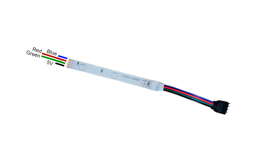
RGB LED strip
I programmed the RGB LED strip connected to the XIAO RP2040 on the latest Fab&Plant PCB version to create a fading in and out effect. I also try a code generated entirely with ChatGPT. I used this prompt: generate a code in Arduino IDE for blinking an RGB LED strip with fade in and out effect. The strip is connected to D0 pin in XIAO RP2040. I got this code:
//Fab Academy 2024 - Fab Lab Peru - Maria Angela Mejia
//Code for RGB LED connected to a XIAO RP2040 using ChatGPT generated code

// Pin definitions
const int greenLedPin = D0;  // Pin connected to the green LED

void setup() {
  // Initialize the digital pin as an output.
  pinMode(greenLedPin, OUTPUT);
}

void loop() {
  // Fade in from off to maximum brightness
  for (int brightness = 0; brightness <= 255; brightness++) {
    analogWrite(greenLedPin, brightness);
    delay(10);  // Adjust the delay for the speed of the fade
  }

  // Keep the LED on for a while
  delay(500);

  // Fade out from maximum brightness to off
  for (int brightness = 255; brightness >= 0; brightness--) {
    analogWrite(greenLedPin, brightness);
    delay(10);  // Adjust the delay for the speed of the fade
  }

  // Keep the LED off for a while
  delay(1000);
}
Code in Arduino IDE for programming the RGB LED strip in Fab&Plant PCB
During this week's exploration I better understood how to approach my final project. It was a great learning experience with output devices.
Conclusions
- The working principle of an output device involves converting electrical signals into a usable form such as motion, sound, or light. Each type of output device has unique mechanisms and processes for this conversion, tailored to its specific function and design. Understanding these principles helps in effectively integrating and controlling these devices in various electronic projects.
- The 9g SG90 Tower Pro microservomotor is a versatile and compact motor known for its lightweight design, precise control, and compatibility with various projects. With its 180-degree rotation capability and ease of integration, it is ideal for applications requiring precise angular movement. The working principle of a servomotor involves receiving a Pulse Width Modulation (PWM) signal from a microcontroller (XIAO RP2040 in this case), which the control circuit reads to determine the desired position. Activated by this PWM signal (from the microcontroller's code), the motor moves the shaft to the corresponding position, with precise control ensured by feedback mechanisms.
- The mini speaker offers compact size, and easy mounting, making it suitable for various applications where space is limited and clear sound reproduction is desired. The working principle of a speaker involves receiving audio signals as varying electrical voltages, which cause a diaphragm within the speaker to vibrate. Activated by these electrical signals (from the microcontroller's code), the vibrating diaphragm generates pressure waves in the air, producing audible sound for humans.
- The RGB LED strip is a flexible and versatile lighting solution that features a series of Red, Green, and Blue light-emitting diodes (LEDs) embedded along a strip. The working principle of a RGB LED Strip involves receiving digital signals to control the color and brightness of each LED. Activated by these signals (from the microcontroller's code), integrated circuits within the strip decode and adjust power levels to the red, green, and blue LEDs, enabling them to emit light in diverse colors and intensities that produce visual effects.
- To finish this task I thank my fellow students and tutors, especially Roberto Delgado for the guidance in this process; Hans Moncca, Silvana Espinoza, Cristian Loayza, and Jose Rodriguez for the team work this week.