Computer-Controlled Cutting
In week 3, the task presented a variant: I worked in teams in the same physical space while simultaneously conducting individual computer-controlled cutting activities, using both a laser cutter and a vinyl cutter, on parametric designs I had previously developed.
Assignments
Group assignments:
- Characterize your lasercutter's focus, power, speed, rate, kerf, joint clearance and types.
- Document your work to the group work page and reflect on your individual page what you learned.
Individual assignments:
- Design, lasercut, and document a parametric construction kit, accounting for the lasercutter kerf, which can be assembled in multiple ways.
- Cut something on the vinyl cutter.
Learning Outcomes
- Demonstrate and describe parametric 2D modelling processes.
- Identify and explain processes involved in using the laser cutter.
- Develop, evaluate and construct a parametric construction kit.
- Identify and explain processes involved in using the vinyl cutter.
Results: Computer-Controlled Cutting
Until this moment I had escaped parametric design. I did not fully understand it, I felt that I should be an expert in design software before try it and I thought that I did not need it. This Fab Academy assignment definitely took me out of my comfort zone and I forced myself to learn. It turns out that parametric design is fun, it makes design for manufacturing efficient and allows the imagination to fly without fear of making mistakes because the parameters are easily modified if necessary. As a result, after trying various shapes and modules, I designed and manufactured this cardboard lamp prototype.
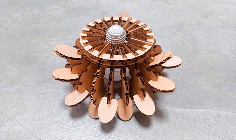
Daylight isometric view
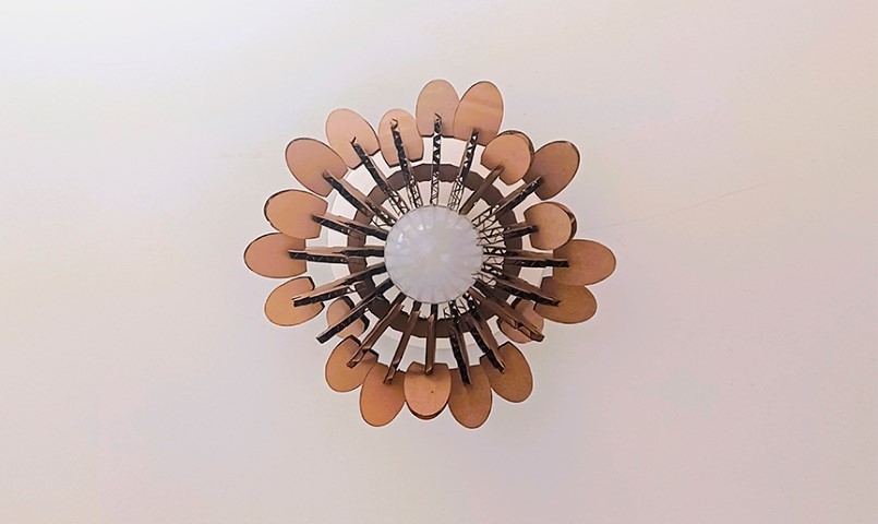
Daylight bottom view
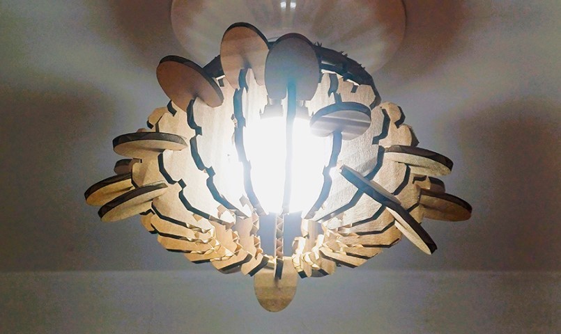
Night isometric view
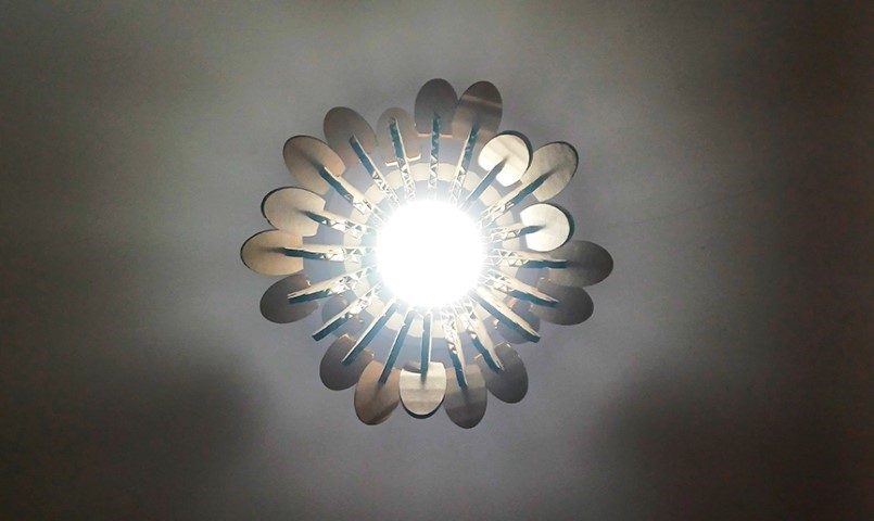
Night bottom view
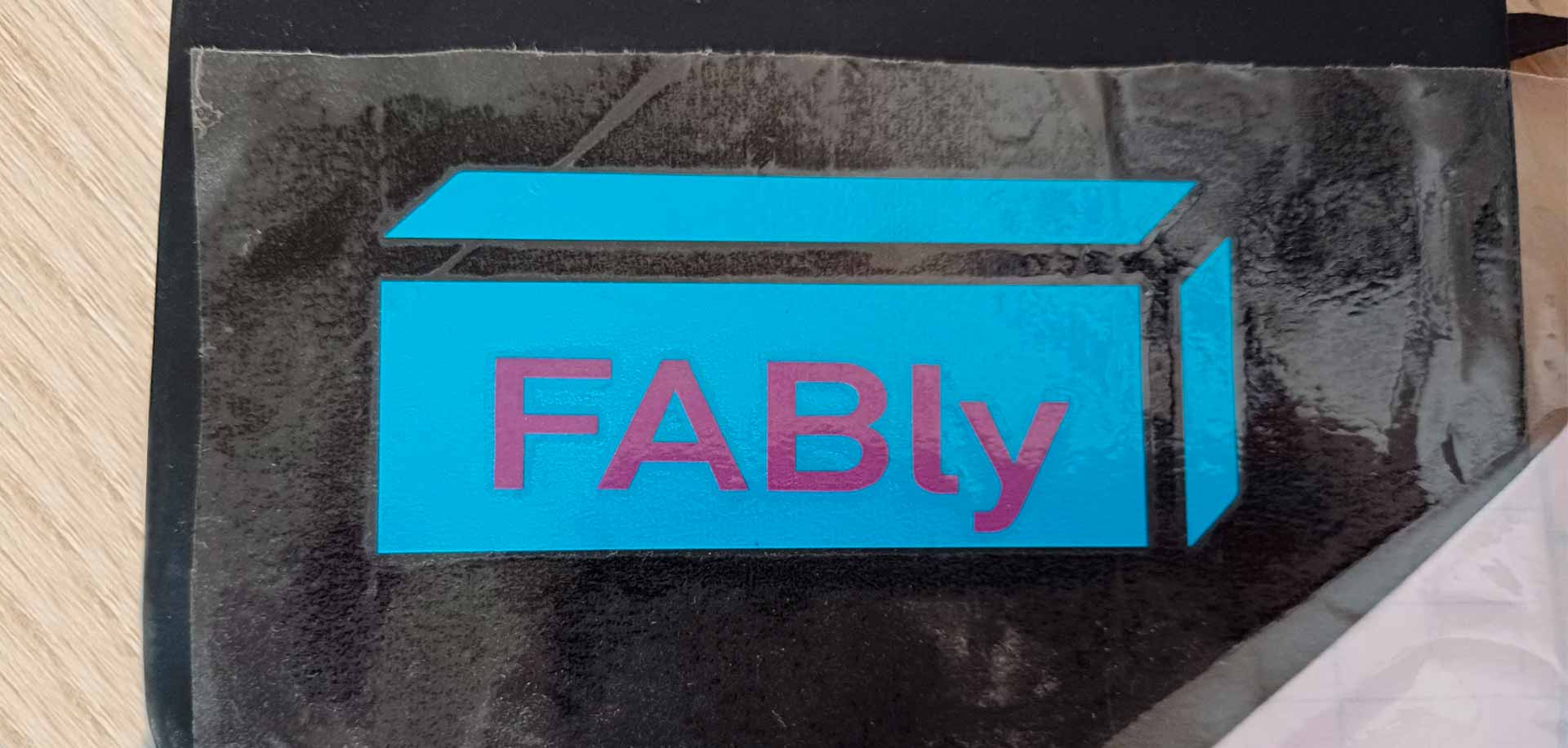
I also made this sticker for my Fab Academy notebook with the vinyl cutter.
FABly sticker made with vinyl cutter
I really enjoy the work I did this week, especially because of the creativity applied and because from now on I only do parametric designs.
Group Assignment: Laser Cutter Parameters
The group assignment page is here.
What I Learned From Team Work
To complete the group work, I went to the iFurniture Fab Lab which is located within the Meliton Carvajal Emblematic Educational Institution, in Lince district, in the city of Lima, Peru. The CO2 laser cutter that the iFurniture Fab Lab has is the C4V model 1390. It has a cutting surface of 1300mm x 900mm.
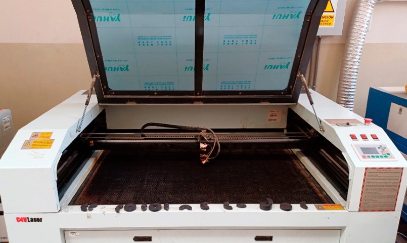
Laser cutter and its controller located on the front right of the machine
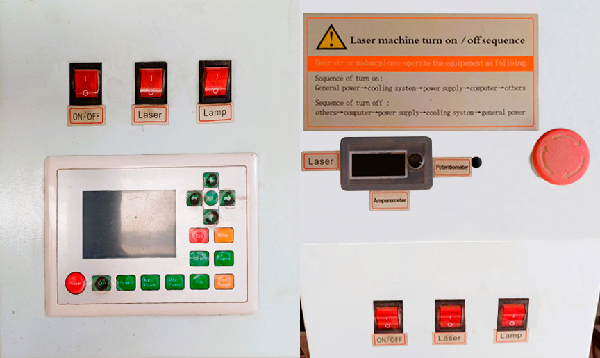
The laser is located on the back and what you see in the cutting area is the head of that same laser. In this Fab Lab, the machine is controlled with RDWorks software that can be used in other machines as well.
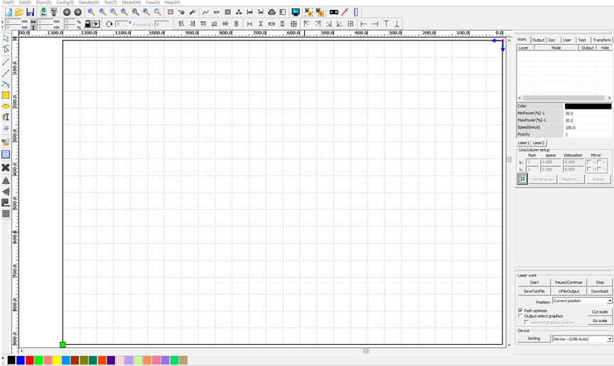
The laser, its head and RDWorks software
Important: While the laser is working, you are not allowed to leave the area in front of it.
How to Use a CO2 Laser Cutter:
- Check the environment. This must be free to walk, without danger of tripping over any cables.
- Select the material you will use, place it on the cutting surface and manually calibrate the nozzle. Use the caliper.
- Configure the cutting parameters in the RDWorks software.
- For each new material to be used, the power/speed test must be carried out to find the best cutting parameter.
- The comb test should also be performed to find the necessary kerf for the selected material.
- Make sure you have good ventilation in the space, as well as that the extractor is operating correctly so that no smoke comes out when the cutting begins.
- When the work is completed, remove the material and verify the cut.
- When you leave Fab Lab iFurniture, leave the space the same or better than how you found it.
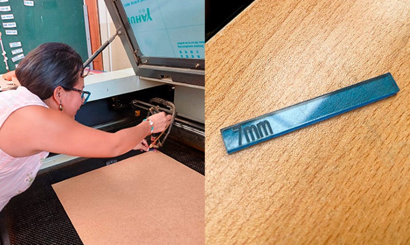
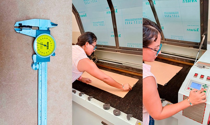
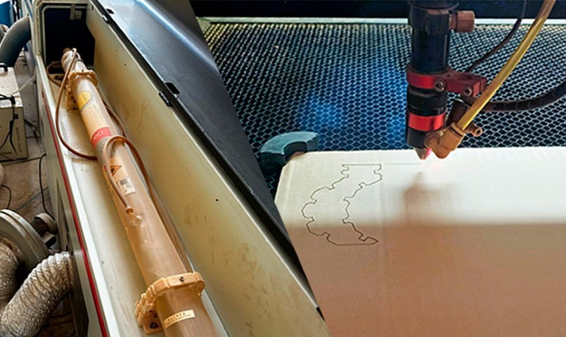
Calibrating the head of the laser and placing the material in the work area for starting the cut
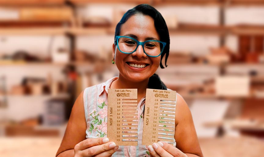
According to the test carried out, the parameters that were able to successfully cut the pieces were 40 power / 10 speed, 50 power / 10 speed, 60 power / 10 speed, 60 power / 20 speed, 70 power / 10 speed and 70 power / 20 speed. According to the comb test for 3mm MDF, the joint that works best is the 3.1mm one.
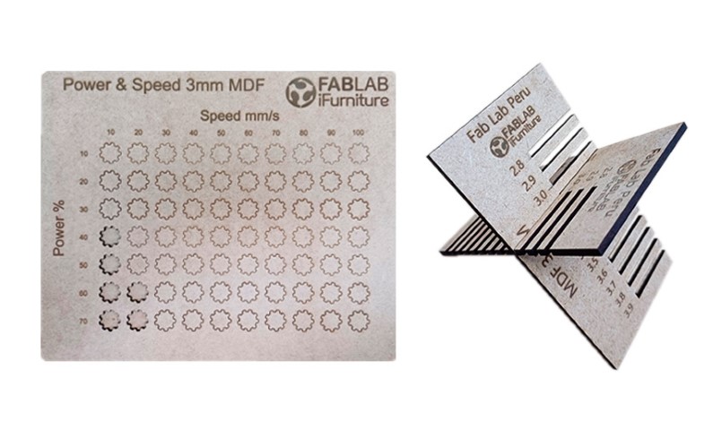
3mm MDF power/speed and comb test
Working with my Fab Academy colleagues for the first time in person was very interesting. Each one shared their digital manufacturing experiences and we spent a nice friday afternoon.
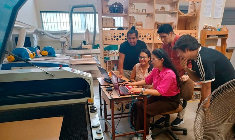
Working the group assignment in iFurniture Fab Lab
Based on the kerf results obtained on this machine, I started designing my first construction kits.
Individual Assignment: Construction Kits
Since my assignment last week, I have continued to explore and use Onshape more frequently to make my designs. Since parametric design was challenging for me, I decided to explore it with Onshape, a program with which I have begun to gain confidence.
Designing a Parametric Cube
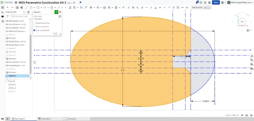
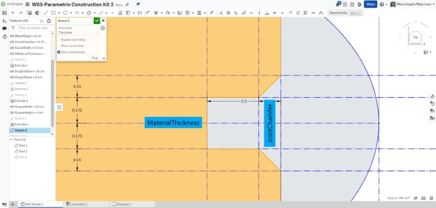
First, before designing my own objects, I wanted to understand parametric design. To do this, I was guided by this video tutorial that uses Onshape to generate a cube based on three parametric modules. For this case, I used parametric variables for the joints (width and height), material thickness, and size of the hollow shapes inside each unit.
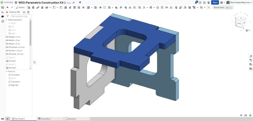

Process of making a parametric cube in Onshape
After making my first object based on parametric modules, I felt ready to continue with my own designs.
Designing a Pentagon Based Parametric Construction Kit
Thanks to the previous exercise, I understood the concept of a figure obtained based on parametric modules. I was ready to create my own kit. I started with something simple: the pentagon.
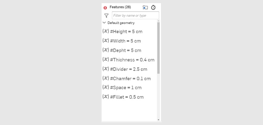
First I set up my diameter variables for the circle inscribed in the pentagon, joint width, material thickness, and joint chamfer. Next, I created the pentagon and assigned the previously created variables to it. Later, I added a union with chamfer to which I assigned the corresponding variables. Then, I copied that union to all sides of the pentagon. Finally, I extruded the figure obtained to give me an idea of what my module would look like after having manufactured it.
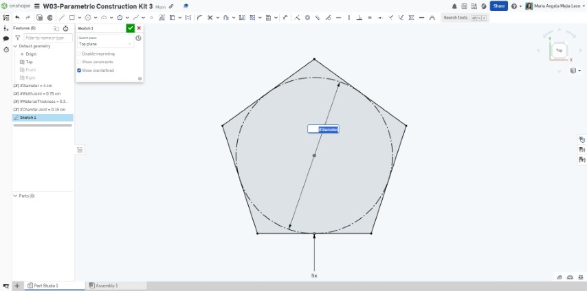
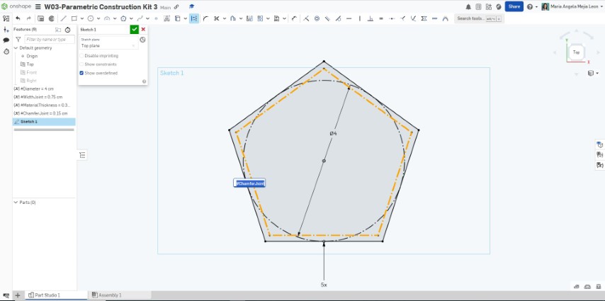
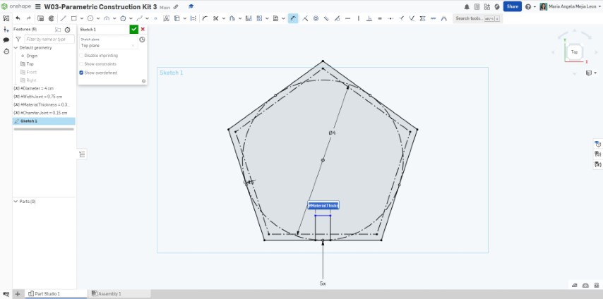


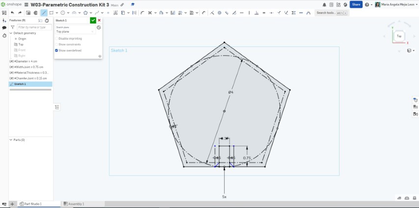
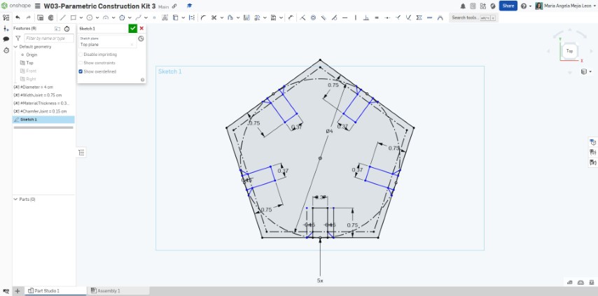

Process of making a parametric pentagon in Onshape
This video shows the complete process.
After designing my first parametric building kit, I wanted more. I found it quite simple and fun, so I decided to create something a little more challenging.
Designing a Funnier Parametric Construction Kit
First of all, I decided to look for inspiration and created this board on Pinterest to collect references and possible designs. I found several lamp designs that I liked and based on that, I created my own lamp based on three parametric modules. I followed the same steps taken to design the parametric pentagon. In this case, my variables were: CapWidth, CapHeight, BulbHeight, MaterialThickness, JointWidth, and JointChamfer.
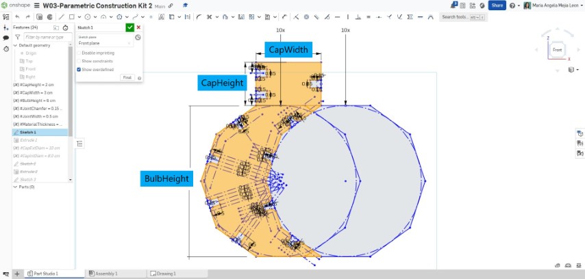
First parametric module that will cover the bulb

Joint detail
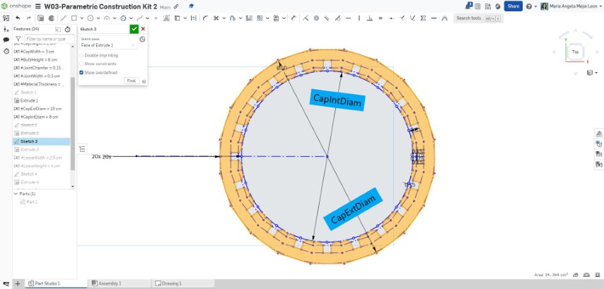
Second parametric module that will unite and shape the first modules

Joint detail
Third parametric module that will shape the light that passes through the lamp
Joint detail
Creating this lamp took me longer than creating the pentagonal module, although it didn't seem more difficult to me. I just needed to understand how it would be linked to the light bulb and from there, propose measures that would allow the lamp to function properly.
You can find the file worked on Onshape for this lamp here.
Cutting the First Construction Kits with CO2 Laser Cutter Parameters
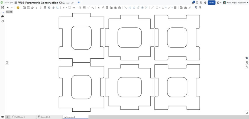
I cut the cube and parametric pentagon in 3mm MDF using the parameters achieved in the group assignment: 40 power / 10 speed. According to the comb test for 3mm MDF, the joint that works best is the 3.1mm one.
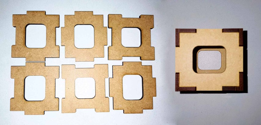
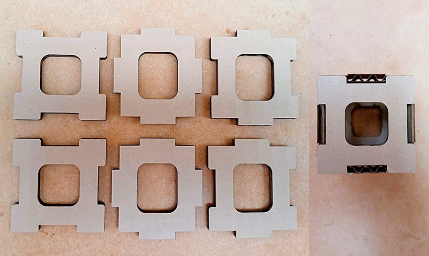
3mm MDF modules of construction kit 1
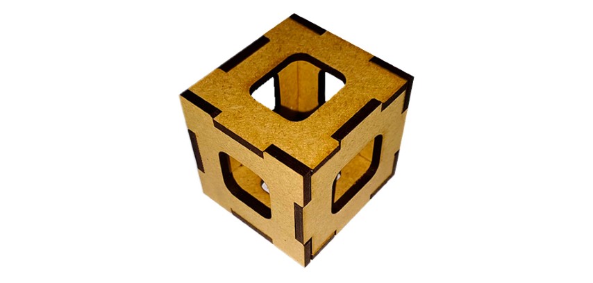
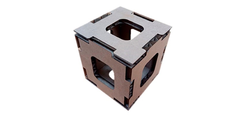
3mm MDF parametric cube
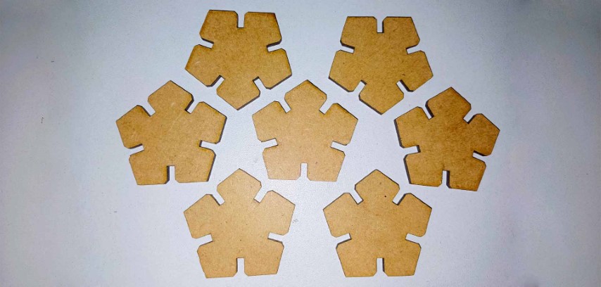
3mm MDF modules of construction kit 2
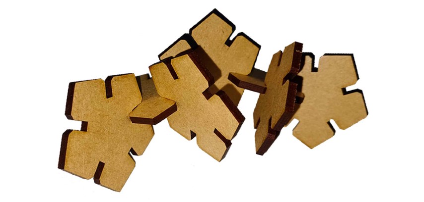
A way to connect the MDF modules
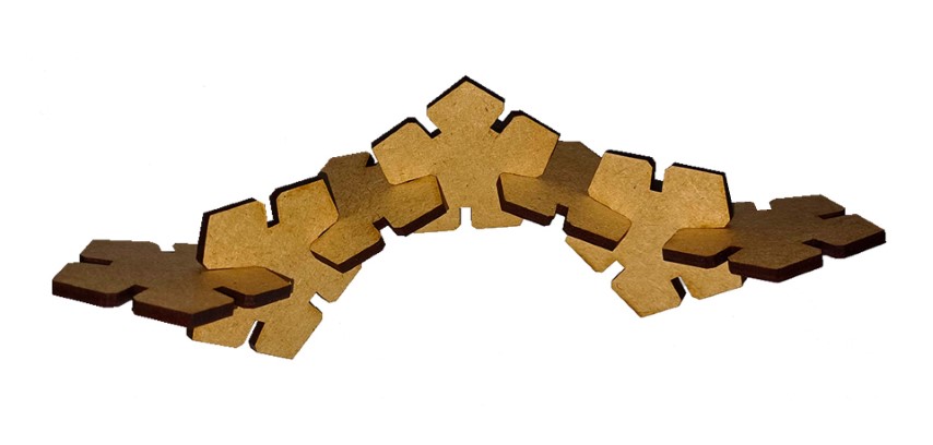
Another way to connect the MDF modules
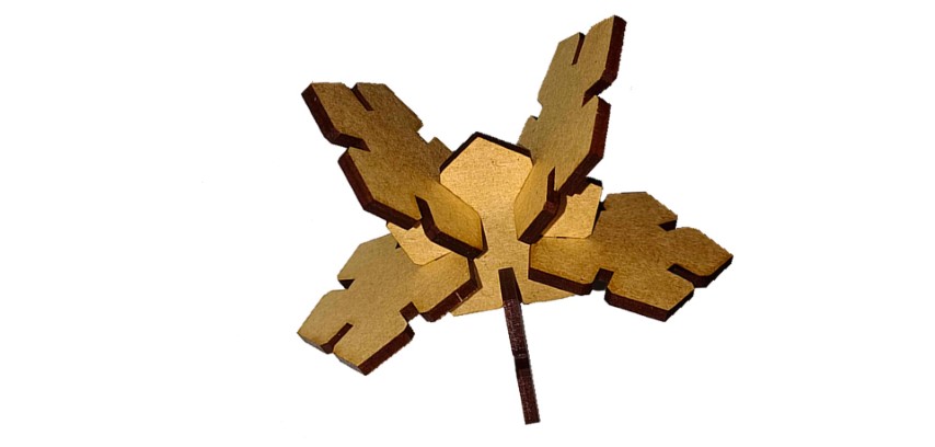
And another way to connect the MDF modules
The parameter values identified with the power/speed tests and the comb worked correctly when cutting the parametric modules.
Since the laser cutter I used the most is the one that I own, I went home to identify the parameters I could use.
How to Use a Diode Laser Cutter (or the story of my first almost fire in a laser cutter)

Important: While the laser is working, you are not allowed to leave the area in front of it. That is how I was able to put out the sparks that started coming out of the burning material.
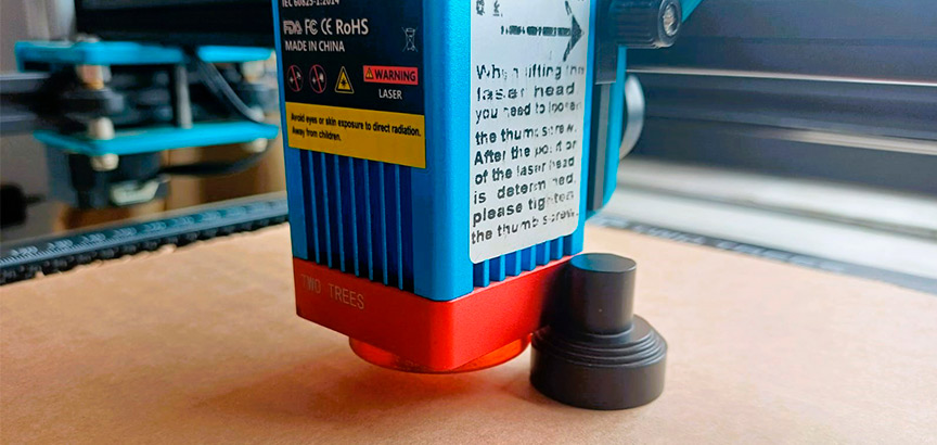
The diode laser cutter I have at home is the Two Trees TTS-55. It has a cutting surface of 300 x 300mm. I used Lightburn software that can edit, and control not only this laser cutter, but can be used with other machines.
To use this laser cutter you must:
- Check the environment. This must be free to walk, without danger of tripping over any cables.
- Select the material you will use, place it on the cutting surface and manually calibrate the nozzle. Use the caliper.
- Configure the cutting parameters in Lightburn program.
- For each new material to be used, the power/speed test must be carried out to find the best cutting parameter.
- The comb test should also be performed to find the necessary kerf for the selected material.
- Make sure you have good ventilation in the space. This machine does not have an extractor fan, so it should always be cut with the surrounding windows open and the door open to generate cross ventilation.
- When the work is completed, remove the material and verify the cut.
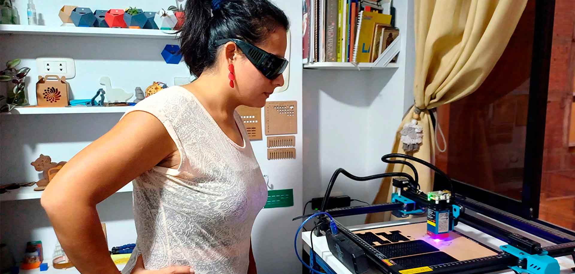
Calibrating the diode laser cutter
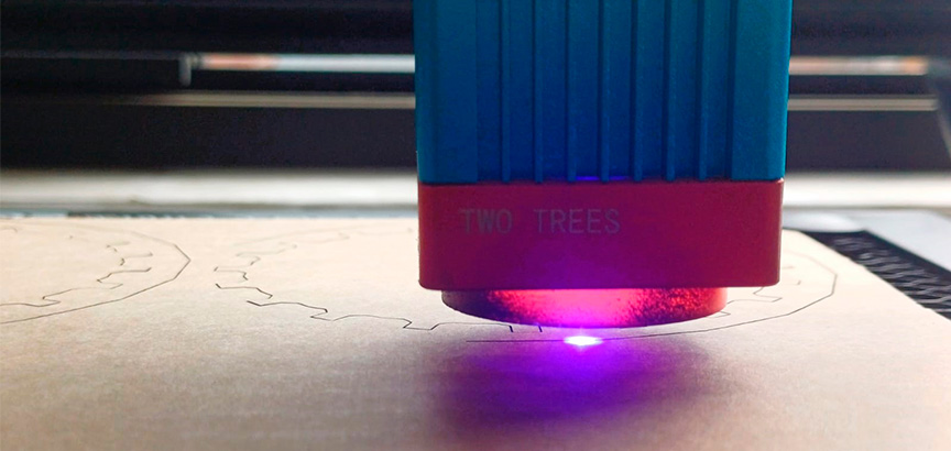
Diode laser cutter working
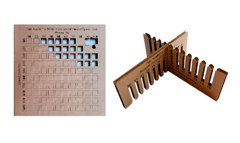
4mm cardboard power/speed and comb test
When I was performing the power/speed test with different parameters, when the speed was lower and the power higher, the cardboard caught fire a little. Since I was next to the cutter, I stopped work immediately and with the force of the air coming through the window, the sparks quickly went out.
Cutting the Parametric Construction Kits in Cardboard
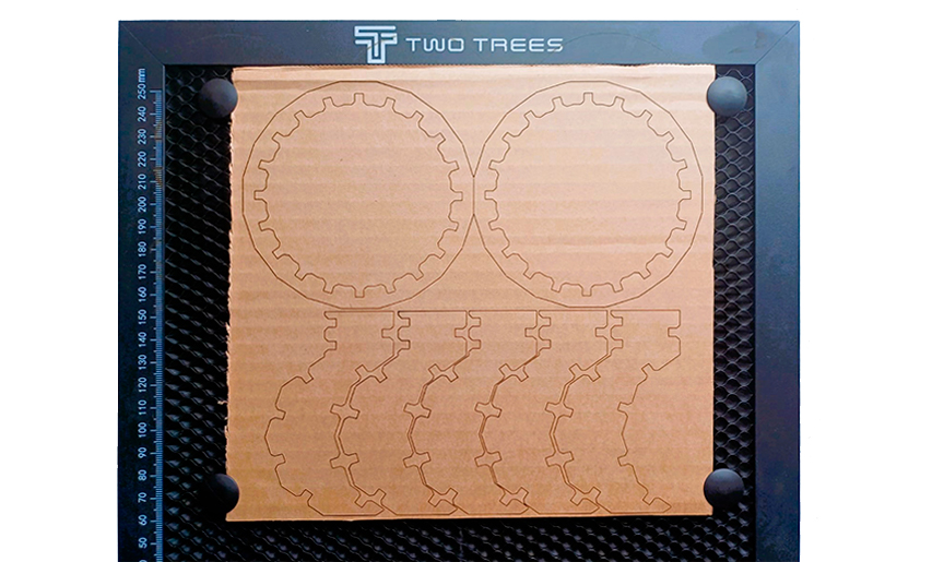
To continue with my individual work, I configured the ideal cutting parameters: power 80%/speed 300mm/min
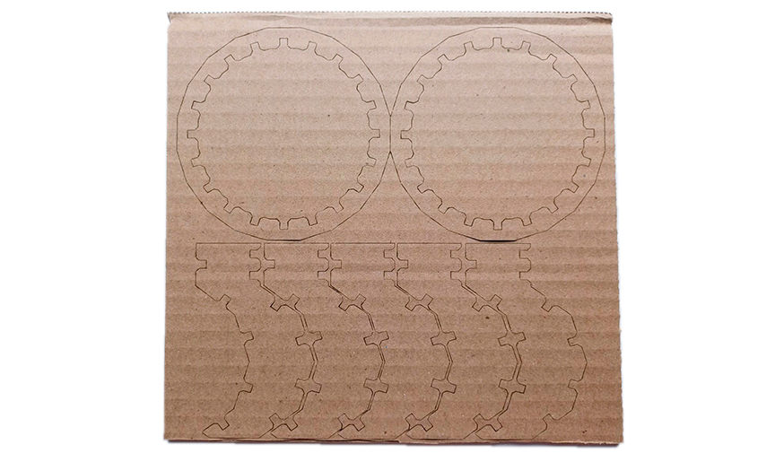
Cutting cardboard modules of my individual assignment
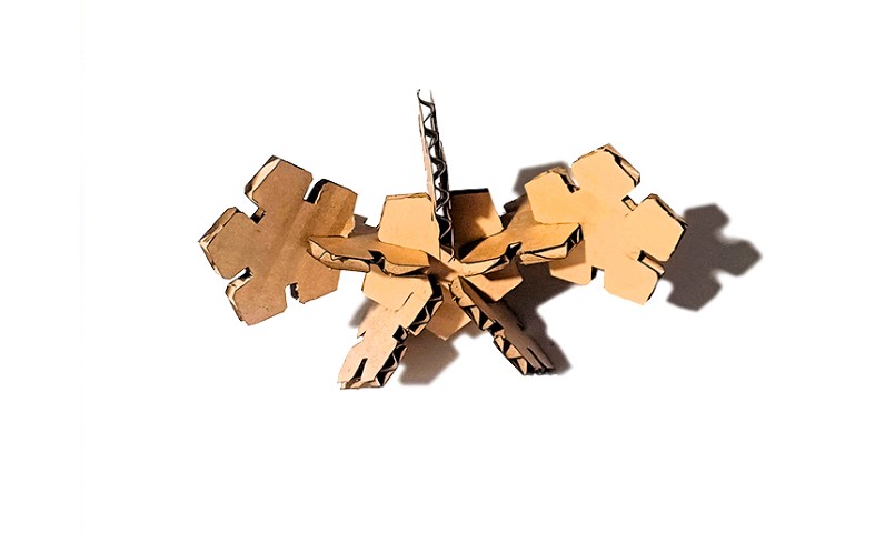
Cardboard parametric cube
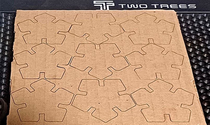
Cutting cardboard modules of my individual assignment
A way to connect the modules
Another way to connect the modules
And another way to connect the modules
The parameter values identified with the power/speed tests and the comb worked correctly when cutting the parametric modules.
Cutting the Parametric Lamp
Finally, it was time to cut and test the modules of the lamp I designed. For this case, I tried another of the parameters that worked in the power/speed test: 90%/400mm/min.
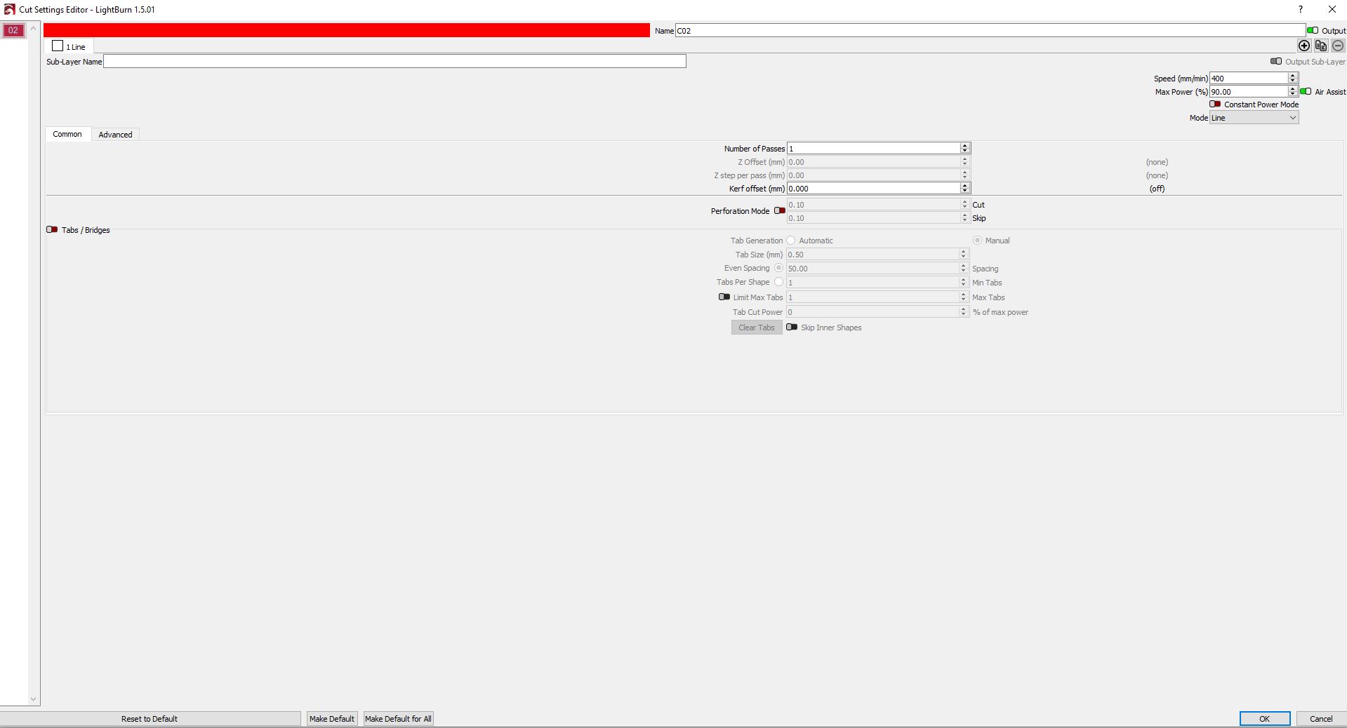
Setting up the cutting parameters

Preview the cut in Lightburn
Front cut
Back cut
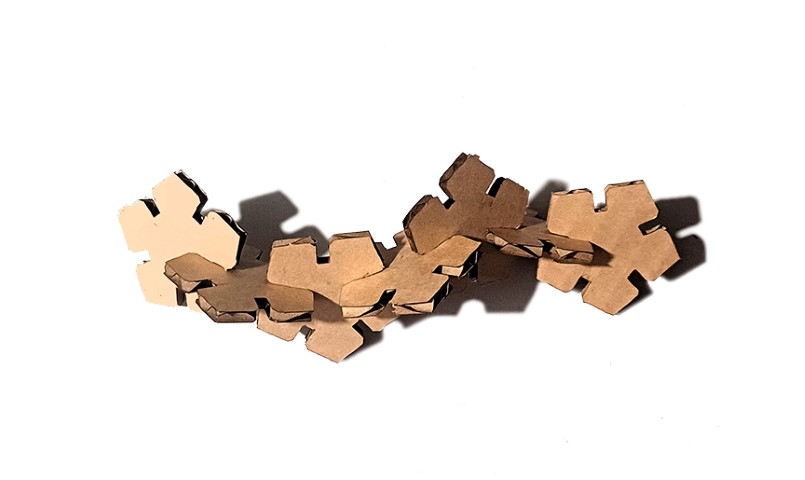
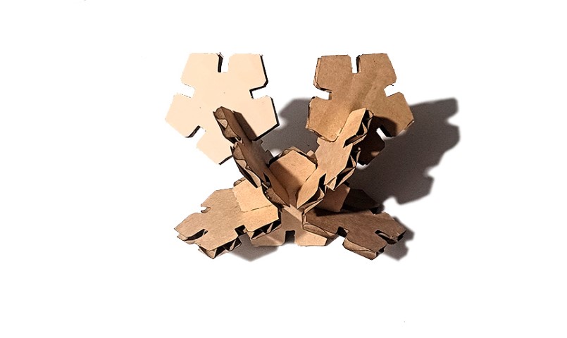
Daylight isometric view
Daylight bottom view
Night isometric view
Night bottom view
Designing this lamp was quite simple and the possibility of modifying the measurements because it is a parametric file opens up many possibilities. I have definitely fallen in love with parametric design.
Individual Assignment: Vinyl Cutting
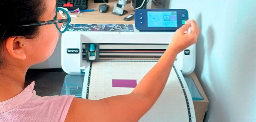
For this task, I am using the Brother ScanNCut CM650W vinyl cutter. I thank companies Diseños Chéveres and Almond Store for lending me their machine to finish this task. This machine is a scanning, cutting and drawing device that allows you to work with the following materials: paper (up to 360gr), butter paper, 100% cotton, vinyl (adhesive and textile), adhesive magnet (1.6mm). It has a touch screen (from where cutting configurations are made), a 30cm x 60cm work area and WiFi connection. This machine is compatible with .fcm and .fc1 files that are obtained after working or importing the files on the Canvas Workspace online platform.
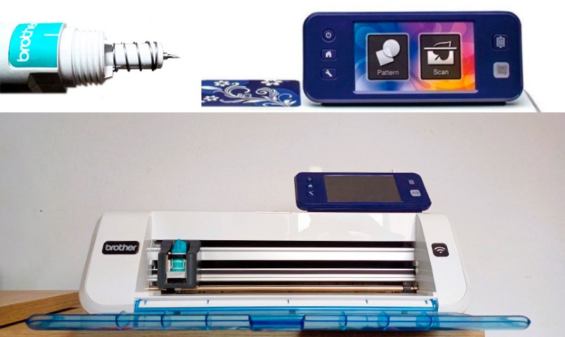
Brother ScanNCut CM650W vinyl cutter
The steps needed to create and make a sticker were as follows:
- I created a 2D design in Illustrator which I then saved in .SVG format.
- I connected my computer via USB cable to the vinyl cutter.
- In the Canvas Workspace online platform, I imported the .SVG file.
- I downloaded the file generated by the platform to the vinyl cutter via the wired connection. This can also be done via WiFi connection.
- I opened my file in the vinyl cutter.
- On the screen, I set the cut to level 3 and also physically did it on the machine blade.
- Now everything is ready to send it to cut!
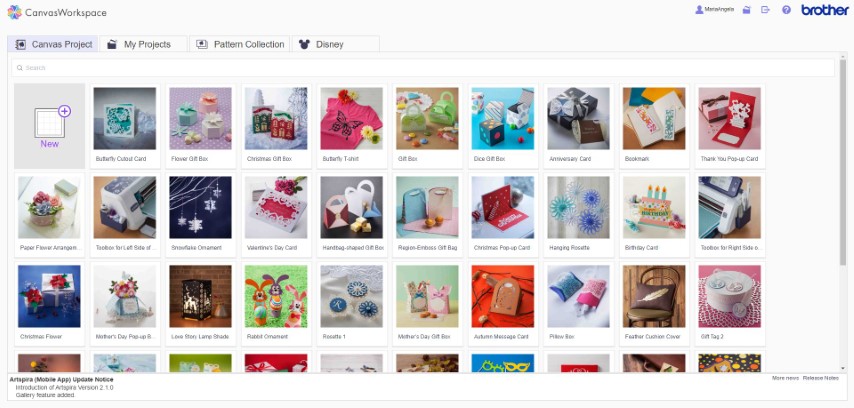
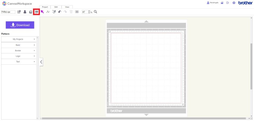

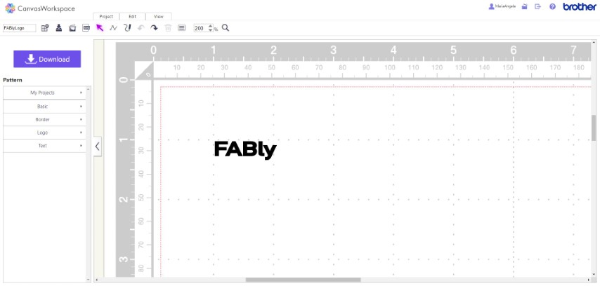

Process of making a two color sticker in the vinyl cutter
After performing a small test cut of a square shape on the vinyl paper and checking that the settings are correct, I continued with cutting the complete pieces.
Once the vinyl cutter finished cutting the different colored pieces, I used transfer paper to join both layers and finish my sticker. For accomplish it, I followed this steps:
- After both pieces of the sticker are cut, I carefully weed away the excess vinyl from each layer using the spatula. This leaves only the desired parts of the design on the vinyl backing.
- I cut a piece of transfer paper slightly larger than my design and peeled off the backing of it for carefully applied it over the first layer of the design, ensuring it adheres smoothly.
- I aligned the second layer of the design over the first layer and pressed down firmly on the second layer to ensure it adheres well to the first layer.
- I carefully peeled off the backing of the second layer, leaving the combined design adhered to the transfer paper.
- I placed the combined design on my notebook surface, ensuring it was straight and aligned properly. After that I pressed down firmly on the transfer paper, then carefully peeled it away, leaving the sticker design securely adhered to the surface.


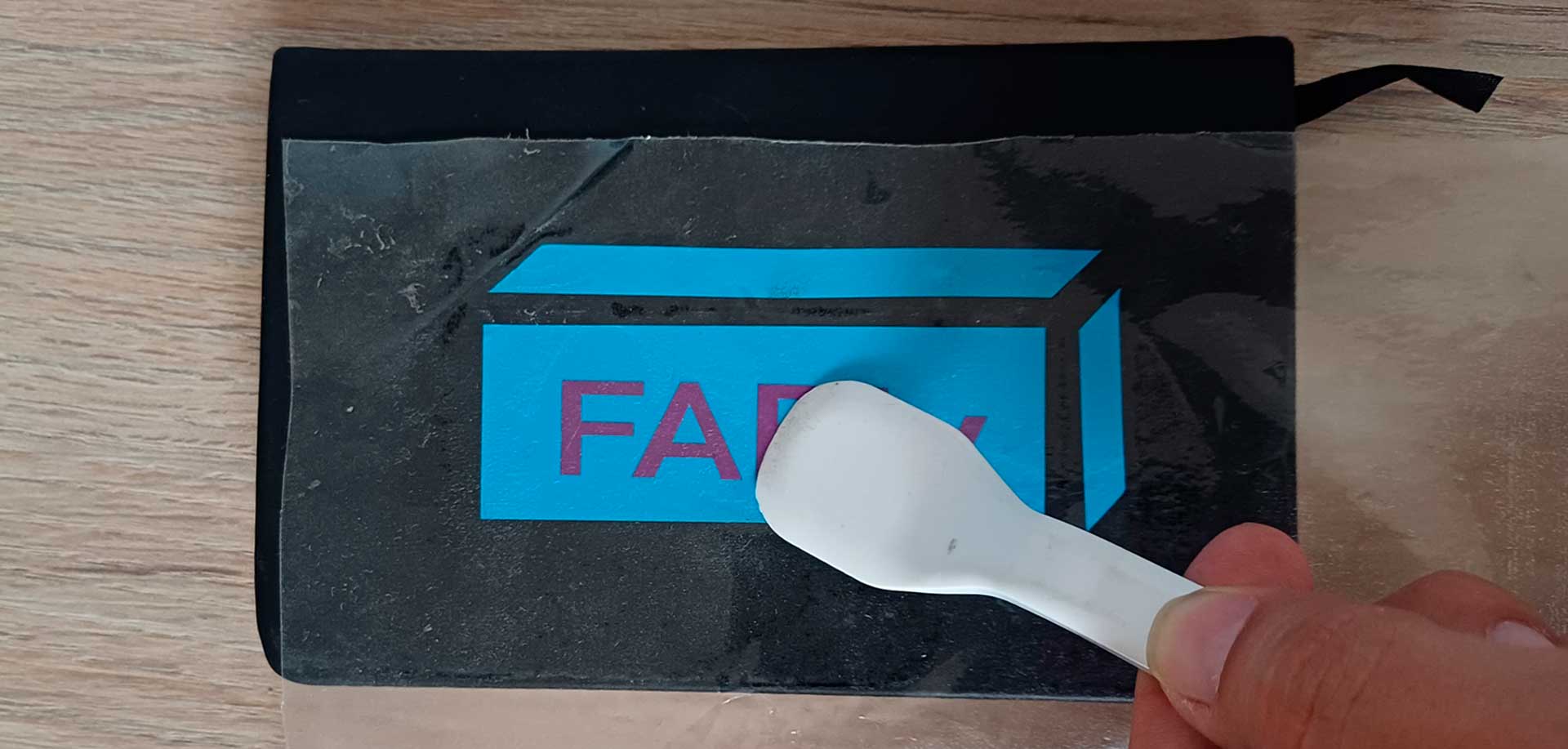
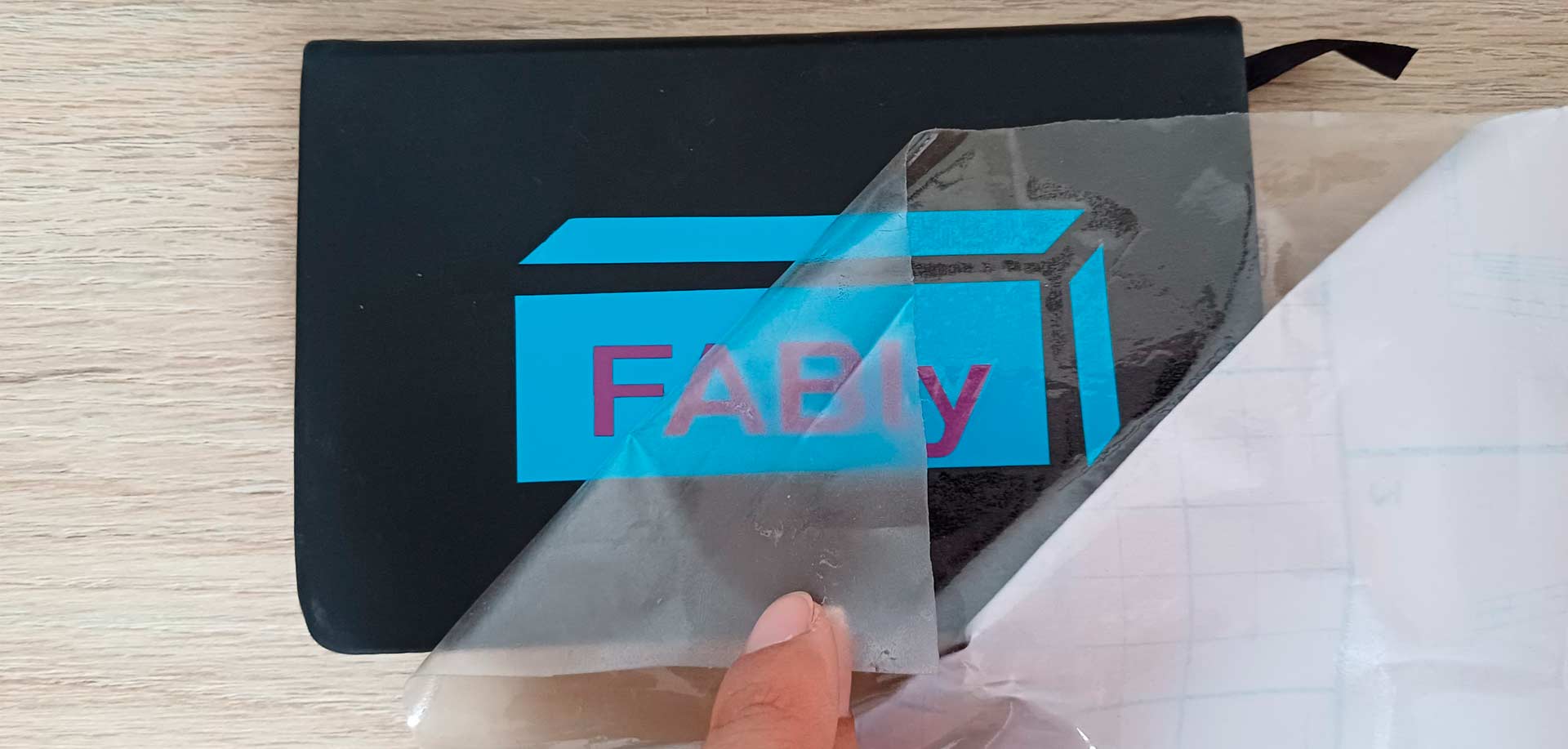
Using transfer paper to stick the two colors of adhesive vinyl
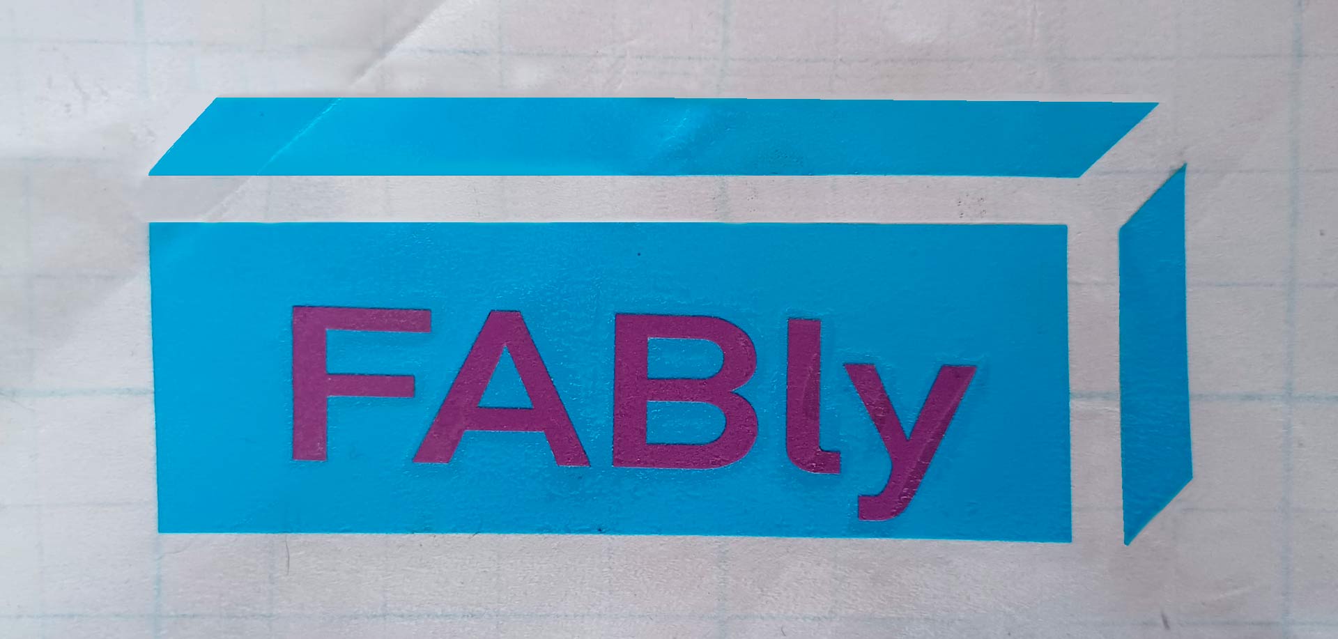
Finally, this was the result of this transfer process!
FABly sticker made in the vinyl cutter
The vinyl cutter is an interesting machine that I still need to explore more, as well as gain the ability to work with transfer paper. In fact, this last point was the most complicated of the entire exercise. It was not as easy as I imagined to get all the letters to stick quickly on the light blue vinyl. It took me several tries. I also think I have to optimize the design of the sticker to achieve an easier job with the transfer paper.
For now, I am happy with the result and want to continue exploring with other materials in the vinyl cutter.
Conclusions
- Sometimes what I consider very difficult, it just needed a little space, effort and focus to make it happen.
- Always use joints with chamfer.
- Onshape is a very interesting program, but when I work on joints at angles other than orthogonal ones, the excessive use of constraits can be somewhat tedious for the eyes.
- Kerf is the width of material that the laser cutter (or other cutting process) removes as it cuts (article where I found the definition here). The kerf will be different depending on the material used.
- When I worked with 3mm MDF, the kerf was 3.1mm to ensure a good fit.
- When I worked with 4mm cardboard, the kerf was 3.7mm to ensure a good fit.
- Designing taking the cutting kerf into account is important because it allows you to optimize the cut and obtain precise pieces for the intended objective.
- I used the kerf concept before this week when cutting in laser cutters, but now I learned to design focusing on the machine parameters: that means I now design with a different approach.
- The kerf effects applies to a manual process as well because depending on the tool used, there will be a different width from the one we drew on the computer (or by hand).
- It is funnier to work in teams. To finish this task I thank my fellow students and tutors, especially Henry Sanchez, Roberto Delgado, Vaneza Caycho , Cristian Loayza, Silvana Espinoza, Ronal Vilca, Franco Yactayo, Grace Schwan and Jesus Lucero.
Files
- Parametric cube file in Onshape web
- Parametric cube DXF file
- Parametric pentagon file in Onshape web
- Parametric pentagon DXF file
- Parametric lamp file in Onshape web
- Parametric lamp DXF file
- 3mm MDF power/speed and comb test file
- 4mm cardboard power/speed and comb test file
Links
- Fab Academy week 03 class
- Pinterest ideas for parametric objects board
- Onshape
- Parametric cube in Onshape video tutorial
- RDWorks (used with CO2 laser cutter)
- Lightburn (used with diode laser cutter)
- Two Trees diode laser cutter TTS-55
- Brother vinyl cutter CM650W
- Canvas Workspace
- Kerf meaning and importance
- Online Gif maker
- Video smaller