7. Embeddeded programming
This week, my classmates and I worked on milling boards for and using two different chips (SAMD11C and ATTiny412) in order to blink an LED with them. I was assigned to the SAMD group at first, and I worked with Landon Broadwell and David Vaughn, my group partners, to create and program our SAMD board/chip. Although it would have been easier to directly link the SAMD and ATTiny boards to our laptops, we had to program them through the RP2040 boards we made a few weeks ago, which complicated things a bit.
Research and Planning
I began this week by looking through Adrian Torres’s Quentorres website for any references to the SAMD11C chip and how to program it. Although I didn’t find too much pertaining to programming, I found a link to his SAMDino chip, which my classmates and I believed would be the best board for the SAMD11C chip. Because of this, we began looking through his website, which was linked on the Quentorres documentation.
After opening Adrian Torres’s SAMDino documentation, I scrolled down until I found what I was looking for, which were the trace and schematic files for milling it. In addition to this, the documentation included a complete list of materials, which was very helpful for the next few steps. Thank you to Adrian Torres and his SAMDino documentation for making this possible!

Milling
After downloading the trace files onto my computer, I began trying to mill the SAMDino file. I did this by following the milling workflow my classmates and I created during electronics production week. There were no real issues while milling the board. The finished mill is shown below.

However, when my group members and I tried to actually solder things onto it, we realized that there was something wrong with the board. Even though I had already imported the file into Fusion 360 and saw that it matched the one on Adrian Torres’s website, when the board was actually milled, it came out different for some reason. Several copper pads at the top of the board (for the conn headers) were missing, and, more importantly, all of the pads for the button were missing as well. Because of this, we realized that we had to find a way to fix the trace file for the board. We struggled a lot with this until Landon Broadwell figured out a way to use modsproject.org to convert the trace png on Adrian Torres’s website into an .nc file, allowing us to mill the correct board. A picture of this new file is shown below.
There was one inconvenience with this file, which was the fact that the file took 30 minutes to mill when it should’ve taken less than 10 minutes. We later found out that this was due to a change while converting the png file to an .nc file. Because of this change, the milling machine would go over each trace 3 times instead of just once.
Once it finished milling, we could begin soldering components onto the board. The first thing my group and I did was go back to the parts list in the SAMDino documentation and gather all the parts we could from our lab. Although this took a significant amount of time, we ended up being able to gather almost everything. The only part which we weren’t able to find was the 3.3V regulator. We later found out that our lab had run out of these regulators and they wouldn’t be arriving until the day before the next week started. Because we didn’t know this at the time, however, we ended up continuing to use this design; this was something which would become an issue later on.
In the meantime, I began soldering the board. This process went relatively well with all of the parts fitting on nicely. Other than the one missing component, I managed to fully solder all of the parts onto the board. However, because we couldn’t actuallly use this board without the missing voltage regulator, we decided to look for an alternative board that we could use to program the SAMD11C with.
Converter Board
While in the process of milling/soldering the SAMDino, we also realized that we needed a converter board. IMPORTANT: THIS BOARD IS NEEDED IN ORDER TO TRANSFORM JTAG (WHICH IS THE OUTPUT OF THE SAMD11C) INTO SWD. While the SAMDino has a 4-pin connector, the board which we planned on connecting it to used a 10-pin connection header. Therefore, we would need a board between them to convert between these two different connector types. The png we found for the converter board is shown below.
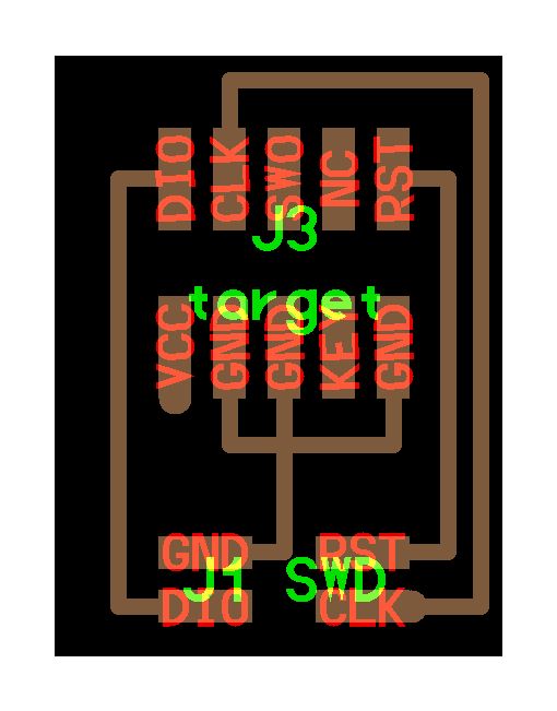
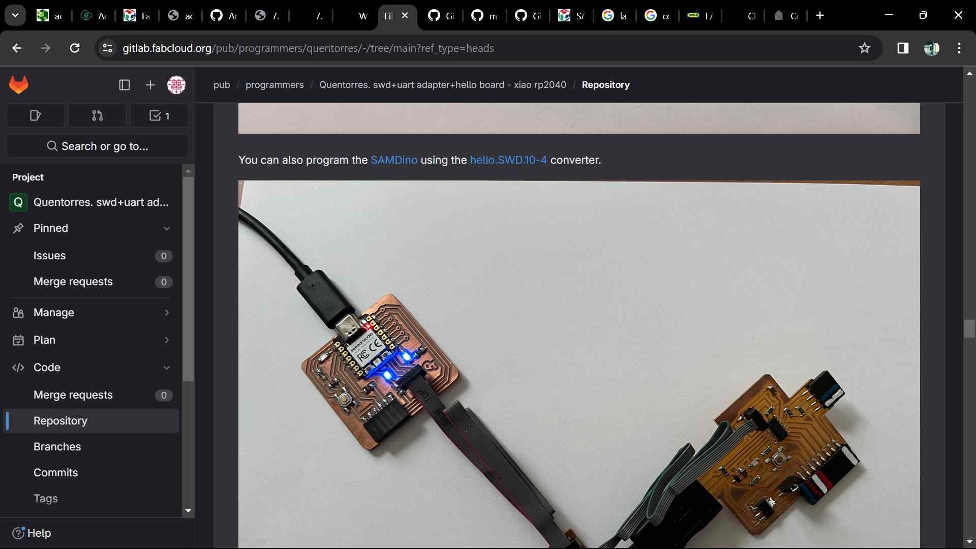
We ended up realizing that we could use the same method as the previous board (using modsproject.org) to convert the png into an .nc file which we could then import on the milling machine. After milling, this board was very easy to solder, as there were only a few parts to solder on. Unfortunately for this converter board, however, we soon found a new board (the hello board) which we could use to program the SAMD chip. This meant that we didn’t actually end up using this converter board to upload code to the SAMD.
Important note: the board that I refer to above and further down in my documentation as the “hello board” is actually the programmer board board that the Samdino is using, so just keep that in mind when you hear the name “hello board”.
Hello Board
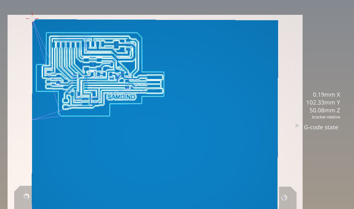
After searching for a while, we realized that Adrian Torres had included another SAMD11C board in his documentation other than the SAMDino. Unfortunately, this board was only included as a png of its traces, meaning that we originally weren’t able to mill it. To solve this, we again used the same solution as the previous boards with modsproject.org, converting it into an .nc file. The file for this new board is shown in the picture below.

The side effect of converting the png to an .nc file was the same as when we milled our previous board; this print was scheduled to take around 10-15 minutes, which didn’t make a lot of sense considering its very small size. Despite this, we ran the print anyways, and it ended up coming out fine after being milled.
We initially planned on still using the SAMD11C free dap programmer to program the SAMDino board; after realizing that we were missing the 3.3V regulator, however, we ended up switching over to solely using the hello board (which kinda means we wasted a bunch of time milling, soldering, and stressing over the other board but oh well) because it was much simpler. Although this board also needed a regulator, we were able to find one on a scrap (discarded) board. We proceeded to use a heat gun and soldering iron to remove this regulator from the other board and solder it onto our board.
Soldering this board was much easier than milling the SAMDino because of how small it was. The whole process took only a short amount of time, and this is the board we ended up programming to blink an LED (instead of using the SAMDino).
Programming Part 1: Interacting with an input/output device
Arduino RP2040
Before programming the SAMD chip, I had to modify my RP2040 accordingly. To do this, I first downloaded the following file from the Fab Academy schedule.
free_dap_rp2040.uf2
Then, I plugged in my RP2040 to my computer, held the B button, and pressed R; this made my RP2040 show up when I opoened file explorer. From there, I simply pasted the uf2 file I just downloaded into the RP2040’s drive and I was done.
IMPORTANT CLARIFICATION: Although I planned on programming the SAMD11C using the Quentorres board I made in week 4, I ran into many issues that you will see below which made me switch away from using it to programm the SAMD chip. Instead, I ended up simply using a USB-A adapter and plugged my board directly into that to program it. Again, to clarify, I did not use the RP2040 from my Quentorres board to program my SAMD chip, I used a cord which was connected directly to my computer.
SAMD11C
After modifying my RP2040, I could start to program the SAMD chip. I started by going back to Adrian Torres’s Quentorres documentation for some guidance on how to begin. There, I found mentions of flashing a target using edbg, which I wasn’t familiar with. After consulting a few of my classmates, I found a link on the Quentorres documentation which led to an installation for the FAB Sam Core, which has embedded edbg. This FAB Sam Core also allows you to select the “Generic D11C14A” as a board, which isn’t available by default in Arduino. On the FAB Sam Core’s github page, I copied the URL below.
https://raw.githubusercontent.com/qbolsee/ArduinoCore-fab-sam/master/json/package_Fab_SAM_index.json
I proceeded to open Arduino IDE and went to Files > Preferences > Additional Board Manager URLs. This is where I pasted the above URL, giving me access to a board library which includes the Generic D11C14A that I needed.
Now that I had gotten what I needed in Arduino IDE, I moved onto the next step, which was to run the following code in Windows Powershell.
.\edbg-windows-r61.exe -ebpv -t samd11 -f .\sam_ba_Generic_D11C14A_SAMD11C14A (1).bin
However, when I actually ran it, I encountered the following error:
Error: invalid response during transfer (count = 0/1, status = 0)
I ended up getting stuck here for a while until our instructor, Mr. Dubick, told us that it would be sufficient to program the SAMD chip directly from our computer instead of using the RP2040 (further clarification: I did not end up usign the Quentorres board to program the SAMD chip), which simplified the programming process by quite a bit. Because of this change, I no longer needed to flash the bin file through my RP2040 which failed above.
Moving on, I had previously gotten what I needed in Arduino IDE (the FAB Sam Core), so I moved onto the next step, which was to actually upload a blink code directly from my computer to my SAMD chip. To do this, I first referenced a pinout diagram of the SAMD chip, shown below.
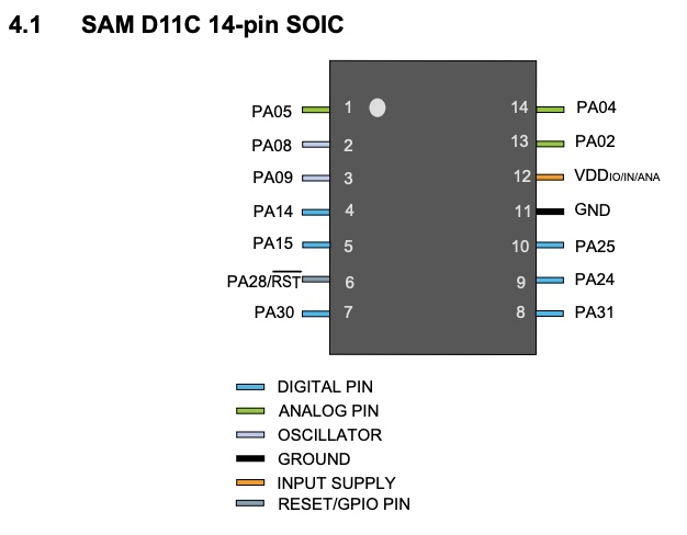
I then opened the blink example code in Arduino IDE and changed the output pin to pin 5, which is where the LED of my board was connected to according to the pinout diagram. The code I used is shown below.
void setup() {
  // initialize digital pin LED_BUILTIN as an output.
  pinMode(5, OUTPUT);
}

// the loop function runs over and over again forever
void loop() {
  digitalWrite(5, HIGH);  // turn the LED on (HIGH is the voltage level)
  delay(1000);                      // wait for a second
  digitalWrite(5, LOW);   // turn the LED off by making the voltage LOW
  delay(1000);                      // wait for a second
}
After writing the code, I made sure all of my settings were configured correctly (board, bootloader size, programmer, etc.). The image below shows my finalized settings (except for port, which should be COM8, as I forgot to plug in the SAMD chip at the time of the screenshot).

After uploading my blink code and waiting for a few seconds, I saw that it had went through successfully and my LED was now blinking accordingly! The video below shows what this looked like.
ATTiny412
After programming the SAMD11C chip to blink, I moved onto the other chip my classmates used this week, which was the ATTiny412. My classmate, Angelina Yang, let me borrow her board for this part. Her documentation can be found here, and I would recommend taking a look at it for a detailed description of the process for milling/programming the ATTiny412 (as I did not do any of the milling or soldering for this board).
Contrary to the SAMD, the ATTiny can be programmed through the RP2040 relatively easily. To begin, I opened Arduino IDE and went to Tools > Board > Board Manager, where I installed the megatinycore pacakge. This package includes support for most of the ATtiny boards, including the 412. Then, I plugged in my RP2040 to my coomputer and connected the ATtiny to the RP2040. I got some help from Angelina Yang for this part, as she showed me how to connect the three jumper wires she used from the ATtiny to the conn headers on the RP2040 board.
After finishing this setup process, I went back to Arduino IDE and opened the same blink code I used for the SAMD chip. I then opened the pinout diagram for the SAMD chip and tried to find which pin the LED on the ATtiny board was connected to. After some time, I chose pin 4 and changed my code accordingly. I also made the LEDs blink faster than on my SAMD board to differentiate the videos (I got this idea from my classmate Landon Broadwell). After uploading the code, it worked! The video below shows the blinking LED on the ATtiny board accompanied by the code I used.
void setup() {
  // initialize digital pin LED_BUILTIN as an output.
  pinMode(4, OUTPUT);
}

// the loop function runs over and over again forever
void loop() {
  digitalWrite(4, HIGH);  // turn the LED on (HIGH is the voltage level)
  delay(250);                      // wait for 0.25 seconds
  digitalWrite(4, LOW);   // turn the LED off by making the voltage LOW
  delay(250);                      // wait for 0.25 seconds
}
Programming Part 2: Communicating with an external device
After completing the first part of this week’s assignment, programming a microcontroller development board to interact with an input/output device, I realized that I had to do the second part of this week’s assignment as well, which was to program a board to communicate with a remote wired/wireless device.
Because I realized the second part of this week’s assignment a while after completing and documenting the first part, I decided to use what I learned during interfacing week (found here) for the second part of this week’s assignment as well. This is because, during the course of that week’s assignment, I wrote code for my Quentorres board (which I fabricated during this week) to use serial communication to communicate with a GUI on my computer. Below, I will explain how I did this and show the final result of this programming. However, you can find a more detailed explanation using the link to my documentation for interfacing week found at the beginning of this paragraph.
Processing
In order to create a GUI on my computer that would allow my board to communicate with it, I used Processing (download link found here). If you want to learn more about what Processing is, you can either click the link above or take a look at my interfacing week documentation mentioned in the above paragraph. Briefly, however, Processing is a simple programming language and IDE that allows beginners to create things such as GUIs without much prior experience. I used it because it was comparatively easier to learn/use than other IDEs and programming languages. Below, I have added the code I used on my computer to create a GUI in the form of a small button. When this button is clicked, it uses serial communication to send a message to my Quentorres board (which is connected to the computer via a wired connection). You can take a look at the comments in the code as well if you are confused about any parts. I will explain what happens when the Quentorres receives this message below the code.
import processing.serial.*;

Serial port;
Button b;

void setup() {
  size(400, 200);
  // Modify the port name based on your system (check in Arduino IDE)
  port = new Serial(this, "COM7", 9600);

  // Create a button
  b = new Button(width/2 - 100, height/2 - 50, 200, 100, "Activate");
}

void draw() {
  // Nothing to draw here
}

void mousePressed() {
  // Check if the mouse is pressed over the button
  b.clicked();
}

class Button {
  float x, y, w, h;
  String label;

  Button(float x, float y, float w, float h, String label) {
    this.x = x;
    this.y = y;
    this.w = w;
    this.h = h;
    this.label = label;
    drawButton();
  }

  void drawButton() {
    PFont f;
    f = createFont("Calibri", 20);
    rect(x, y, w, h);
    fill(0);
    textFont(f);
    textAlign(CENTER, CENTER);
    text(label, x + w/2, y + h/2);
  }

void clicked() {
  println("Button Clicked");
  if (mouseX > x && mouseX < x + w && mouseY > y && mouseY < y + h) { // Checks the position of the mouse to see if it is within the boundaries of the button
    if (port != null) {
      port.write('H');  // Send 'H' to Arduino
      println("Sent command 'H' to Arduino");
    }
  }
}

}
Quentorres Code
When the Quentorres receives the message sent by the code above, it will blink two of its LEDs two times each with a 500 millisecond delay between one another. The code it uses to do this is shown below. Again, you can look at the comments or refer to my documentation for interfacing week if you are confused.
#include <Adafruit_NeoPixel.h>

int ledState = LOW;

void setup() {
pinMode(0, OUTPUT);
pinMode(1, OUTPUT);
Serial.begin(9600);
Serial.println("Arduino is ready");
}

void loop() {
if (Serial.available() > 0) {
    char command = Serial.read(); // Checks for a serial message and assigns it to command
    Serial.print("Received command: ");
    Serial.println(command); // Prints a confirmation message for receiving the "command"

    if (command == 'H') { // Checks if the message received was the correct one (i.e. the one that is supposed to trigger the LED), which in this case is "H"
    ledState = !ledState;  // Toggle LED state
    flashLED(); // Flashes the LED repeatedly
    }
}
}

void flashLED() {
Serial.println("Flashing LED");
digitalWrite(0, HIGH);
delay(500);
digitalWrite(1, HIGH);
delay(500);
digitalWrite(0, LOW);
delay(500);
digitalWrite(1, LOW);
delay(500);
digitalWrite(0, HIGH);
delay(500);
digitalWrite(1, HIGH);
delay(500);
digitalWrite(0, LOW);
delay(500);
digitalWrite(1, LOW);
delay(500);
}
Running the Code
After successfully uploading the above code to my Quentorres board, I went back to Processing and clicked on the start button to run the code on my computer. The video belows shows my board successfully using serial communication to communicate with my computer, an external wired device.
Group Assignment
This week, our group assignment was to read over the datasheet for our assigned chips (in my group’s case, the SAMD) and write any important parts on our group documentation. In addition to this, we also had to compare our chip’s performance and development workflows with those of the other chip’s (the ATtiny412). Our group documentation can be found here.
Individual Contribution
I primarily compared the capabilities SAMD and ATtiny412 chips to see the differences between them. During this time, I saw that the SAMD had much more memory overall as well as more programmable I/O pins, making it more versatile than the ATtiny. In addition to this, the SAMD didn’t require as large of a power supply as the ATtiny (according to their respective datasheets). This specific part didn’t make too much sense to me. If the SAMD is more powerful, why can it function with a weaker power supply? This might just be a mistake in my interpretation, but I couldn’t find any actual evidence on the datasheets that the ATtiny used less power than the SAMD even though it is weaker.
Reflection
This week was probably the most frustrating week so far. My classmates and I (especially people who did the SAMD) experienced many setbacks while trying to mill a board for our chip, as we kept finding new issues that prevented us from making progress. We also experienced setbacks in the form of missing components, specifically the 3.3V capacitor which we waited several days for. Then, when we moved onto programming, we initially tried to program the SAMD chip through the RP2040. Only after hours of trying, however, did we find out how difficult this was before switching to programming directly from our computers. Many of my classmates experienced many issues with edbg at this point as well. In the end though, we did manage to successfully program our SAMD chips, as well as the ATtiny412 chips that some other students made (the ATtiny chips were significantly easier to program, for me at least). In the end though, I did learn a lot about how to program the SAMD and ATtiny chips; I also learned a lot about their capabilities through comparing each board’s respective datasheet. My files for this week can be found here.