6. 3D Scanning and printing
This week, I will work on using a 3D printer to print out a design which I make in Fusion 360. This is similar to our assignment for CAD week, with the difference being that the design we make has to be smaller, as it must fit on the bed of a 3D printer. We will also use 3D scanning to model a real-world object virtually. As for the group assignment, my group (which is the same as last week) of Evan, Alana, and I, will be printing a “torture test” on a Prusa 3D printer. This torture test is a design which tests essential functions of the printer, such as its accuracy and its ability to print at an angle (instead of just placing filament directly vertically). Then, we will analyze this torture test and create conclusions based on its results.
Cadding a Design
I came up with a few iterations of designs this week, but I ended up simplifying it down to a hollow cube (with circular cutouts on each side) containing a sphere which can move freely in the middle. This design cannot be made subtractively it contains a moving object inside of another 3d shape. Before I describe how I created my final design, however, I first want to go over my most promising design prior to simplifying it.
Voronoi Sphere
My original plan for 3D designing was to make a Voronoi sphere inside of a hollow cube (I later found out this was very similar to Adrian Torres’s design for this week; I DIDN’T COPY HIM I SWEARRR). I chose to create this design in Fusion 360, but this design should be possible in any CAD software which supports meshes. I began by first creating a new file, followed by a sketch on the bottom plane. In this sketch, I used the 2-point-rectangle tool to create a 40 mm by 40 mm square. After this, I exited the sketch and extruded the square upwards by 40 mm, creating a cube. The picture below shows what this looked like.

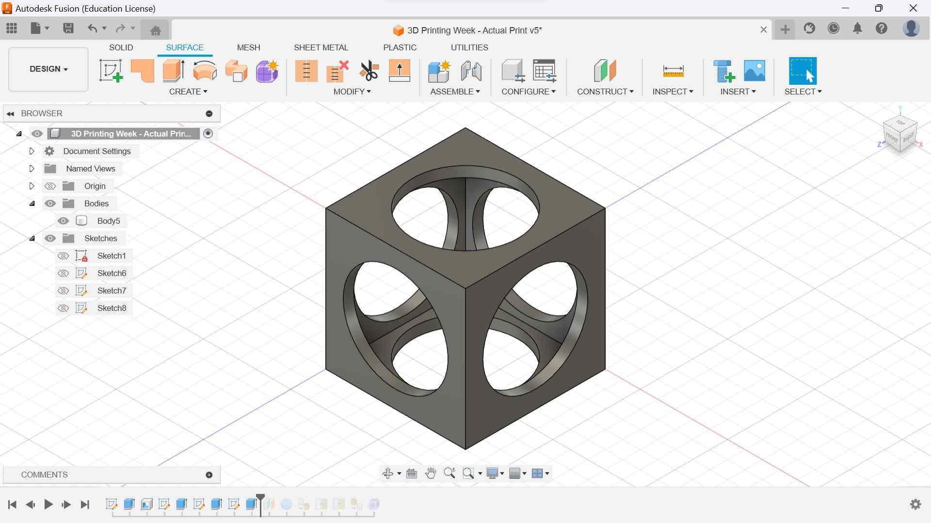
Then, in order to hollow it out, I used the shell tool and set the inside thickness to 3 mm before finalizing it. Now, I needed to create circular holes on each side. To do this, I began by starting a sketch on one of the horizontal sides of the cube. In this sketch, I created a circle (in the middle of the square side) and set its diameter to 30 mm. Finally, I exited the sketch, selected the extrude tool, and extruded the circle -40 mm, cutting through the cube entirely and leaving two circular holes, one on the side of the sketch and another one on the opposite side. I repeated this process two more times for the other four sides, and this is what my design like afterwards.
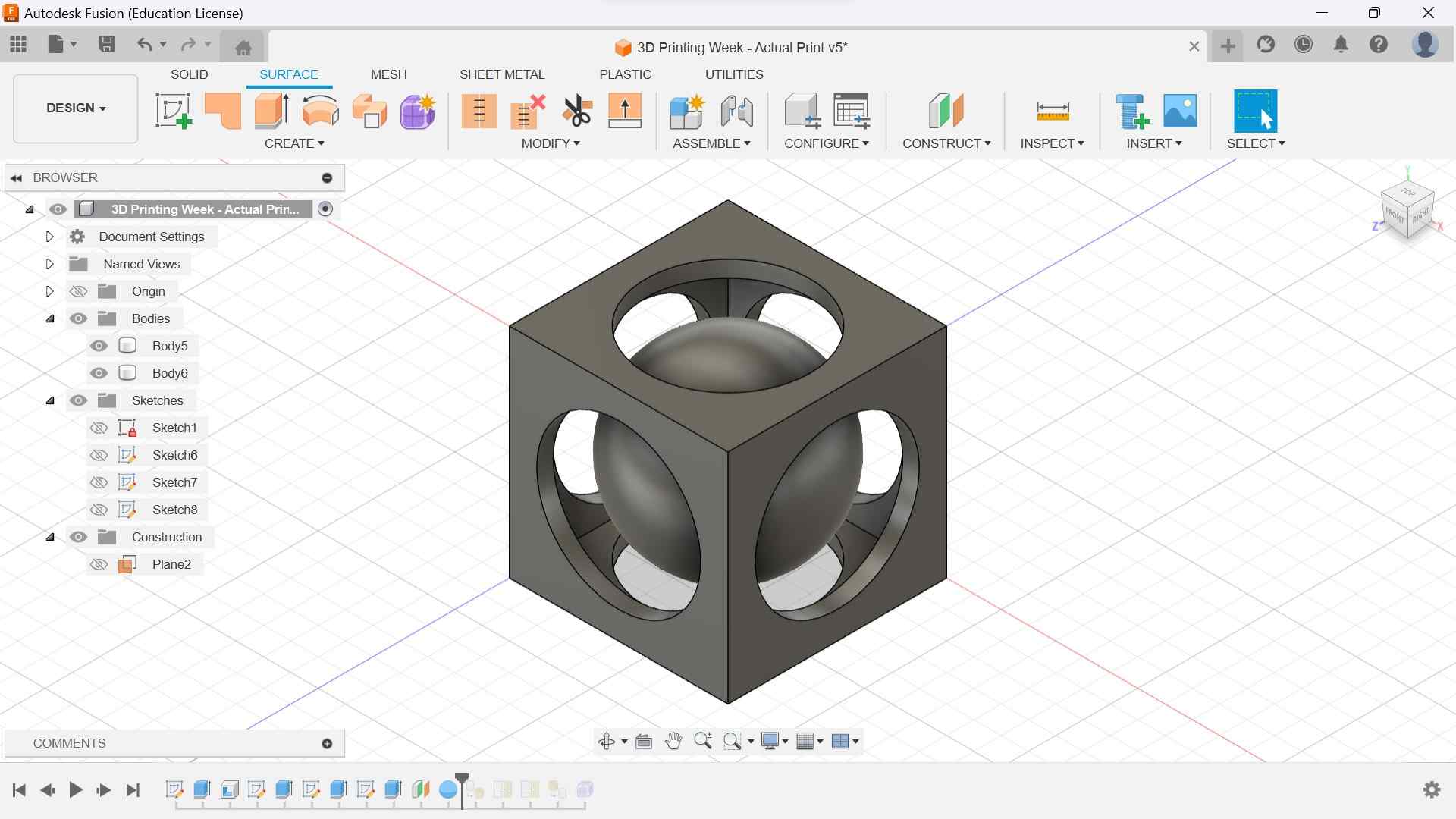
Now that I had finished designing the hollow cube, I could move onto creating the Voronoi sphere in the center. To do this, I first created an offset plane (by choosing the offset plane tool in the toolbar) of the bottom of my cube, moving it up 20 mm to the center of the cube. Then, I created a sphere on this plane, made sure it was directly in the center of the cube, and set it to have a diameter of 35 mm. This was done to ensure it was bigger than the circular holes in the side of the cube so it wouldn’t fall out. The picture below shows what my design looked like after adding the sphere.
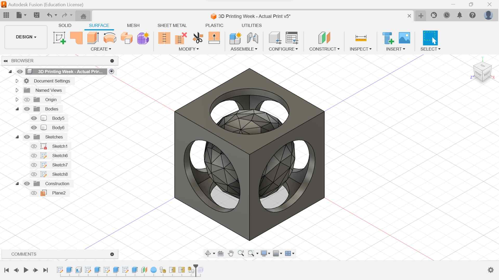
After creating the sphere, I wanted to turn it into a mesh. To do this, I went to the mesh tab, selected the “tessalate” tool, and chose the sphere as the target body. This opened up a column of settings on my screen, prompting me to choose the surface deviation, normal deviation, maximum edge length, and aspect ratio of the mesh. Because I wanted a mesh with as few sides as possible (to make it easier to print), I turned all of these settings as high as they could go, creating a mesh with 1368 triangles.

I then used the “remesh” tool to adjust the faces of the mesh I just made, selecting the new mesh as a target body. Here, the tool offered me two types of remeshing: adaptive and uniform. I ended up choosing adaptive because I felt it looked better. Then, I was prompted to change the density and shape preservation of the remesh. I chose a density of 0 to limit the number of sides my mesh would have. I then chose a shape preservation of 100% to keep the mesh as close to a sphere as it could be. Following the use of the remesh tool, I used another tool, “reduce”, to (you guessed it) further reduce the number of sides on my mesh. I again chose adaptive as the reduction type and set the reduction proportion to 50%. After this, I used the “convert mesh” tool to change the mesh back to a normal body. This is what my design looked like afterwards.
Now that I had the tessalated body, I used the “selection” tool, chose “select edge priority”, hid the hollow cube, and highlighted the entire mesh. Because I chose to only select edges, the faces were ignored and were not selected. Then, I went to the surface tab and chose “create form” while still having the edges of the body selected. After choosing create form, I clicked on the “create” drop-down menu and chose “pipe”. This tool converted all of my selected edges into 3-dimensional cylinders. After creating this structure, I exited the form tab by clicking “finish form” and hid the original tessalated body so that the new structure would show. This is my finished design.

Final Design and Printing
After finishing my design of the voronoi sphere, I exported it from Fusion 360 as an stl file and saved it onto my computer. Then, I opened PrusaSlicer, imported my new design into it, and chose “slice now”. However, this is where complications with my design arose. Because my voronoi sphere didn’t touch the ground in my design, I had to enable supports in order to print it. The problem was, I was not experienced enough with PrusaSlicer to accurately choose where to put supports, so my only options were to either add supports everywhere or only add supports attached to the build plate. The problem with adding supports everywhere was that it would add supports originating from inside the sphere itself, and this problem persisted even when I chose to only add supports on the build plate. The picture below shows what this looked like.
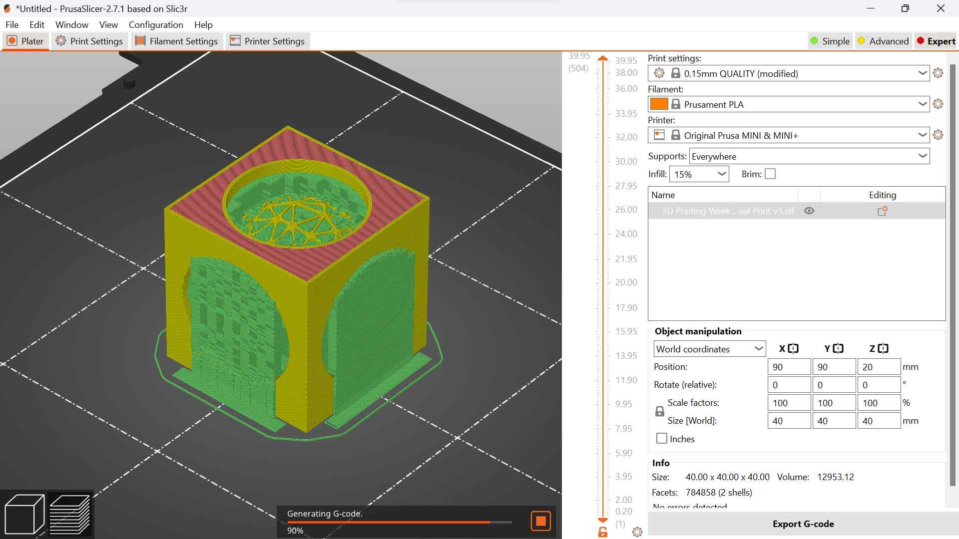
Because of this issue, I eventually decided to just scrap the voronoi sphere and replace it with a regular sphere. To do this, I simply went backward in my Fusion timeline until I had reached the point before I tessalated the sphere. Then, I exported this new design from Fusion, imported it into PrusaSlicer, and checked the slice. This time, if I chose to only add supports on the build plate, the design looked much better. The picture below shows the final design which I chose to 3D print.

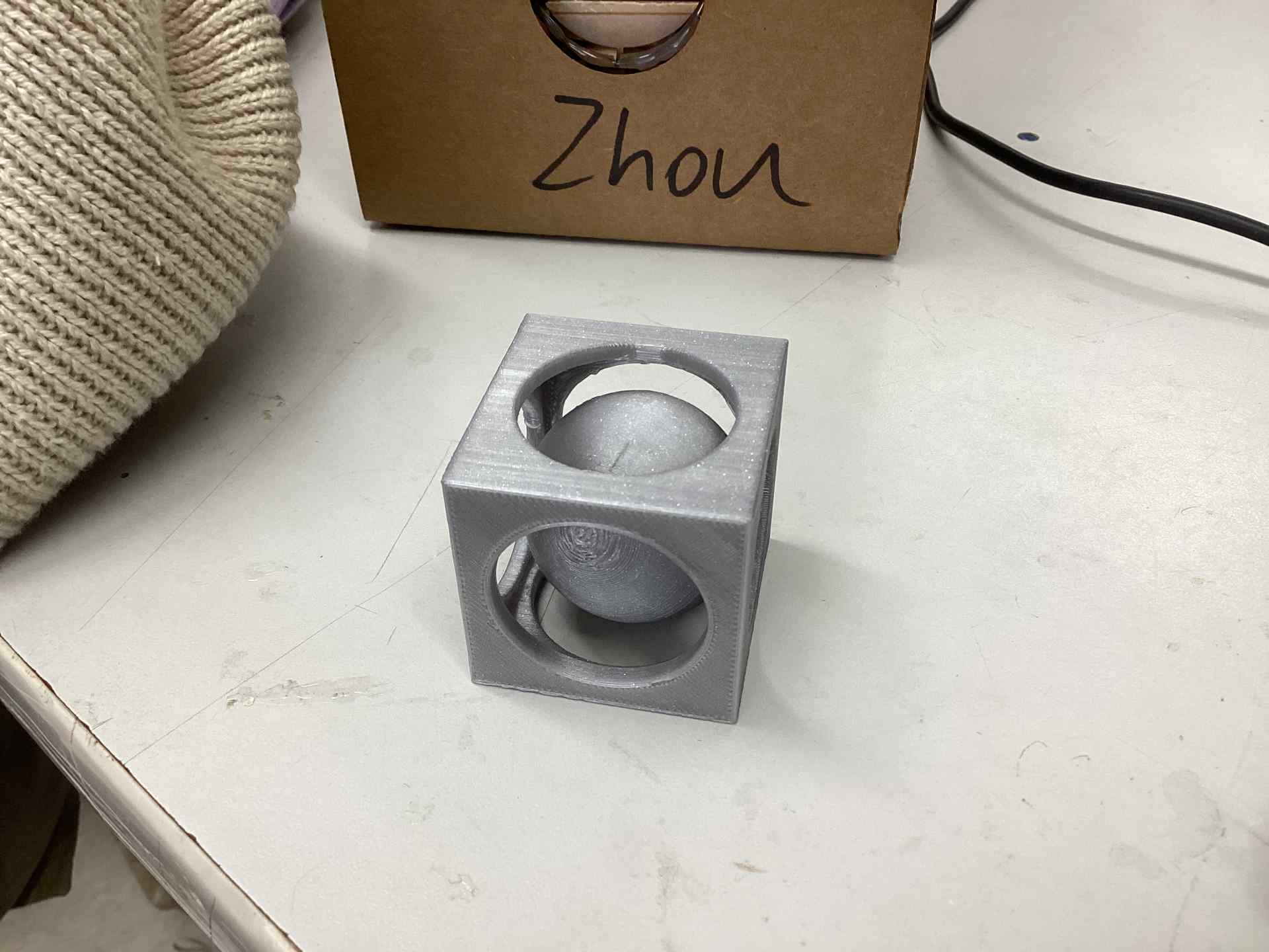
This print ended up taking almost 3 hours, but there were no issues with it and the print succeeded on the first attempt. This is what the finished product looks like:
Print Settings Used
I have listed the settings used for this print below.
- Infill: 15%
- Wall Thickness: ~1.25 mm
- Layer height: ~0.3 mm (My printer has a 0.4 mm nozzle)
- Supports: Build plate only (built-in PrusaSlicer option)
- Material: PLA
3D Scanning
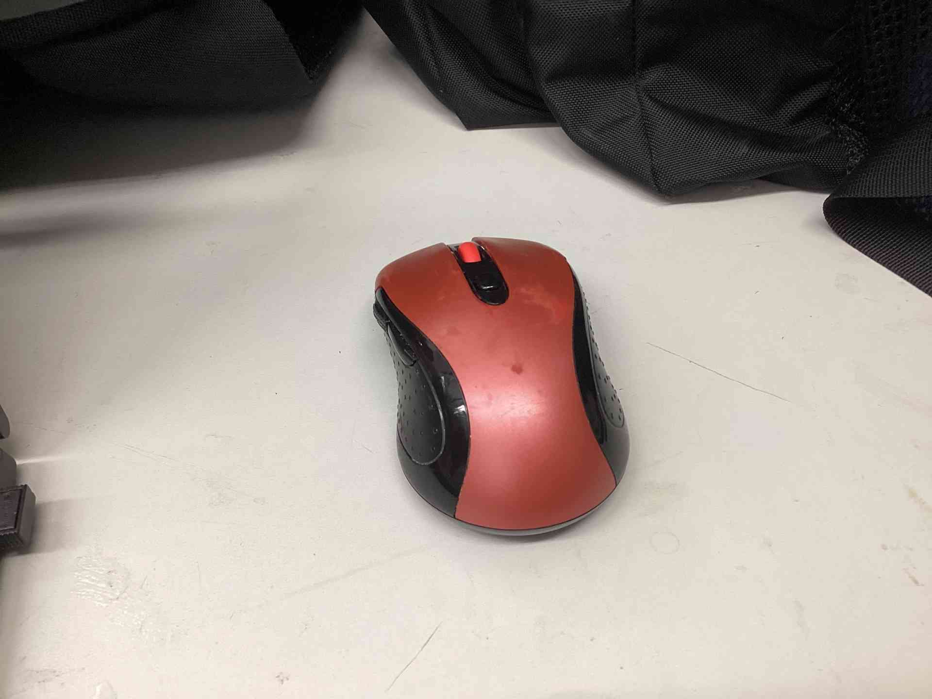
After finishing my 3D print for this week, I moved onto 3D scanning. This part of the week was much simpler than cadding and 3D printing in my opinion, as all I had to do was find an object. The object I ended up choosing was my wireless mouse. A picture of it is shown below.
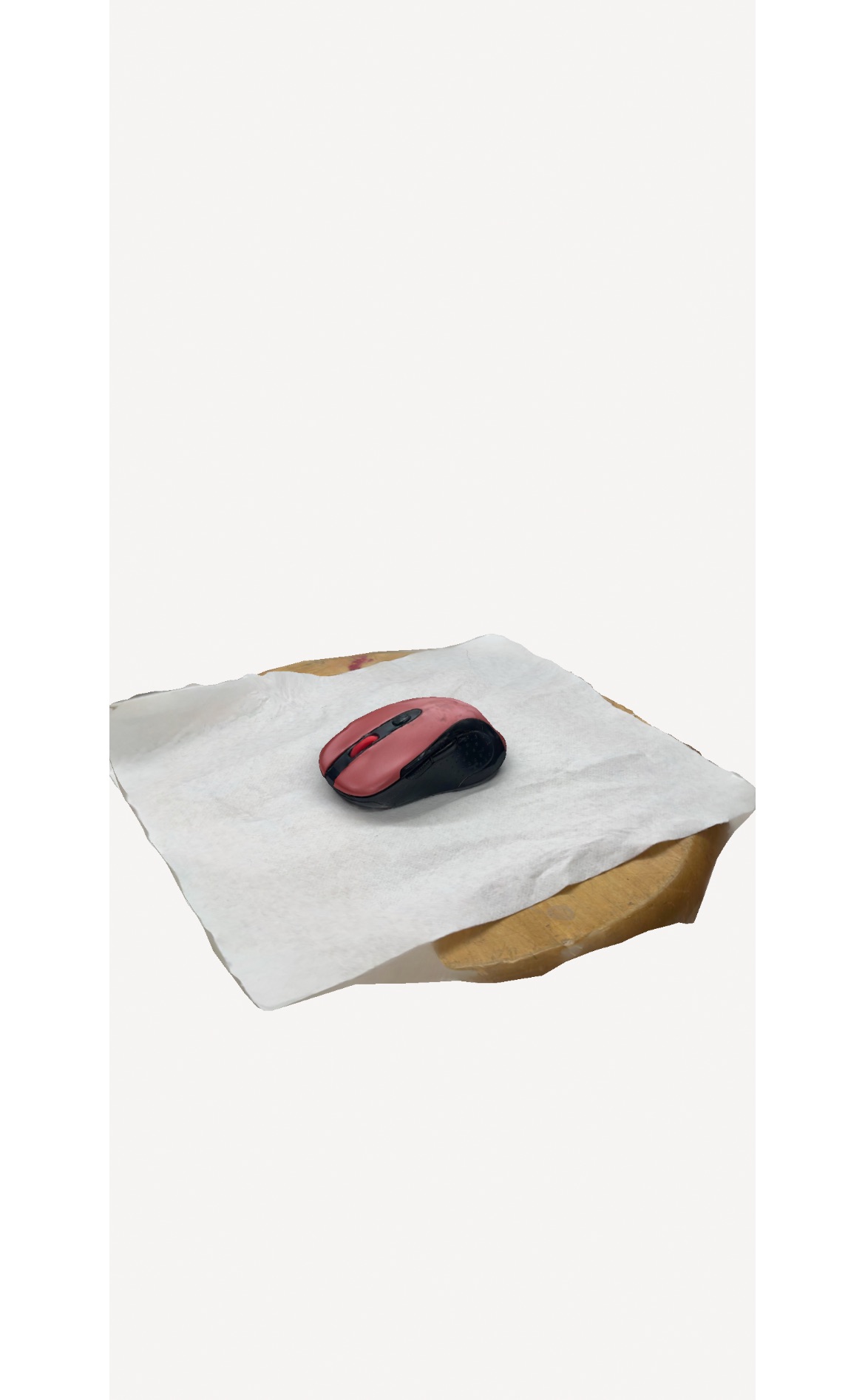
Now that I had my object, I needed a way to actually scan it. For this task, I downloaded an app called Polycam onto my phone and opened it. This app was very simple to use; all I had to do to start scanning was move my chosen object into a space with few to no distracting items around it. To do this, I just put my mouse onto a stool and covered it with a paper towel. Then, when I wanted to begin scanning, the app prompted me to walk around the object while keeping the camerar still. During this process, the app’s automated system took almost 100 pictures of my object from every angle. After this part was over, I only had one thing left to do, upload my pictures, before I could get a 3D scan of my mouse. The uploading process took a few minutes, and, after it was done, I had my 3D scanned file! Unfortunately, this file was in a format I didn’t recognize. This was a relatively easy fix, though. I simply found a file converter on the internet and uploaded my file to it, converting it to an stl file. The picture below shows what my 3D scan looks like.
Why did I use a paper towel?
I put a paper towel below the mouse when I scanned it in order to prevent the scanning software from scanning the stool as part of the object. The reason I chose a paper towel over other similar objects to cover the mouse was because it was the easiest and closest thing in the lab, and also because the white color of the paper towel contrasts nicely with the purple and black of the mouse.
Converting this file into an STL
After scanning the mouse, Polycam outputted the file as a .glb, which is a kind of file used to store 3d object files. In order to convert this file into an STL, I used a website (ex: this website) that converts .glb files to .stl files.
Post Processing
In order to 3D print the scanned model of the mouse that I created, I would follow the steps below.
- Convert the .glb file to a .stl file
- Import the STL file into PrusaSlicer (or another slicer application)
- Export the file as g-code
- Upload the g-code to a 3D printer and print
Preparing the model to be 3D printed
However, because my 3D scanned file has some undesired objects in it (the paper towel), I would also need to remove those objects, namely, the paper towel, for me to begin 3D printing.
After doing a bit of research (see this website for more information), the easiest way I found to do this was thorugh Meshlabs, a free software. The steps for cleaning a 3D scan with Meshlabs are listed below.
- Download Meshlabs and open it
- Go to Files > Import mesh and choose your 3D scan file
- Use tools in either “Edit” or “Filters” to clean your mesh; for example, go to Filters > Cleaning and reparing > Remove isolated. This adjusts the max diameter percentage to remove artifacts and also cleans any artifacts smaller than the desired final mesh
- When you are satisfied with how your mesh looks, go to File > Export Mesh as (you can choose the file type you want here)
For my 3D scanned object specifically, I think that the “Remove isolated” feature would have been very useful, as it would help to separate the paper towel and parts of the wooden stool from the mouse that I was trying to scan.
Group Assignment
For the group assignment this week, I worked with Evan Park and Alana Duffy. The main objective of this assignment was to test the design rules for our 3D printers and find their characteristics; we did this by 3D printing an analyzing a torture test (which was obtained from thingiverse). Originally, we printed one using the Prusa Mini, but this print didn’t end up fully succeeding, and so we reprinted it using the Bambu printer in our lab instead. After it finished printing, we could analyze the torture test. This torture test tested the printer’s ability to handle overhangs, bridging, the accuracy of its prints, and more. In the end, we concluded that the printer was very accurate and could handle everything in the torture test well, with an average inaccuracy of 0.1-0.2 mm (which we found by using calipers to measure its dimensions). The link to our group documentation can be found here.
Reflection
This week was somewhat tedious when it came to my 3D print. I went through several iterations of the same general design before I ended up settling on a comparatively easier design than what I had hoped for. At the same time though, I am still relatively happy with the way my final design turned out. I encountered almost no issues when actually printing my final design, and so the majority of my troubles came from cad. 3D scanning was much easier for me than cadding and 3D printing my design, as it only ended up taking an hour or so. The final scan was also very accurate to the physical object which I chose, which I am happy about. The link to my files this week can be found here.