3. Computer Aided design
This week, I began to use and experiment with different CAD softwares to model different components, including my final project.
Autocad Fusion: Final Project Draft
The first CAD software that I used this week was Autocad Fusion, or Fusion 360. Because this was the CAD software which I had the most experience with going into this week, I decided to created a rough 3d model of what my final project would look like.
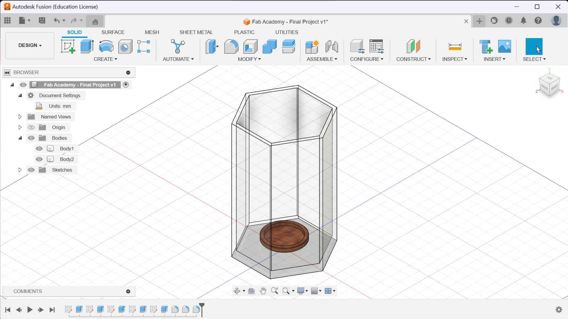
I started with a hexagonal sketch on the bottom plane, as shown in the picture below:
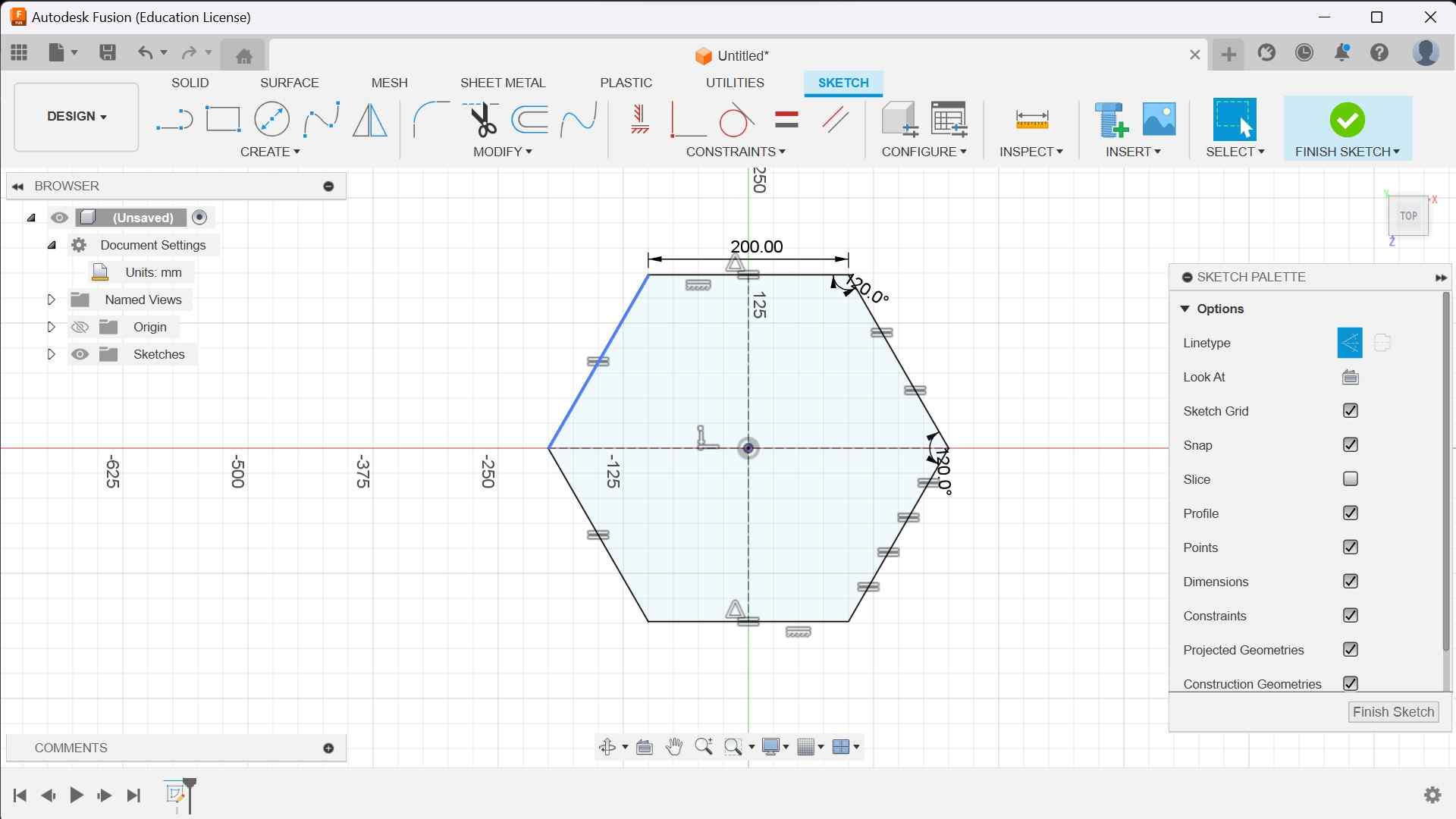
This hexagon was dimensioned with side lengths of 200 mm. These lengths are not final, as I only used them as a way to figure out how to scale my components relative to each other. My actual final project’s measurements will likely be very different from the CAD versions. Anyways, after creating this sketch, I extruded it upwards by 600 mm.
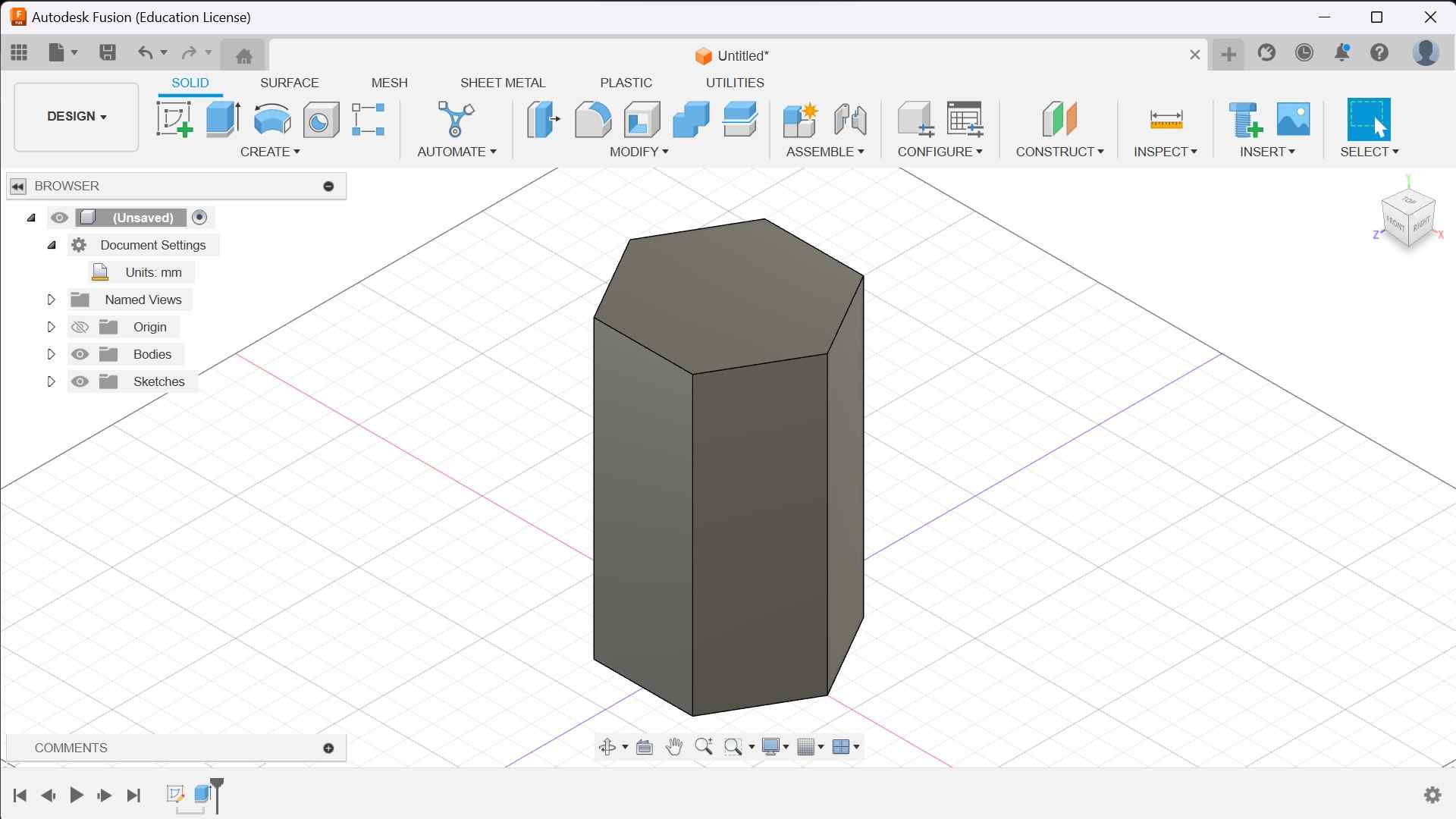
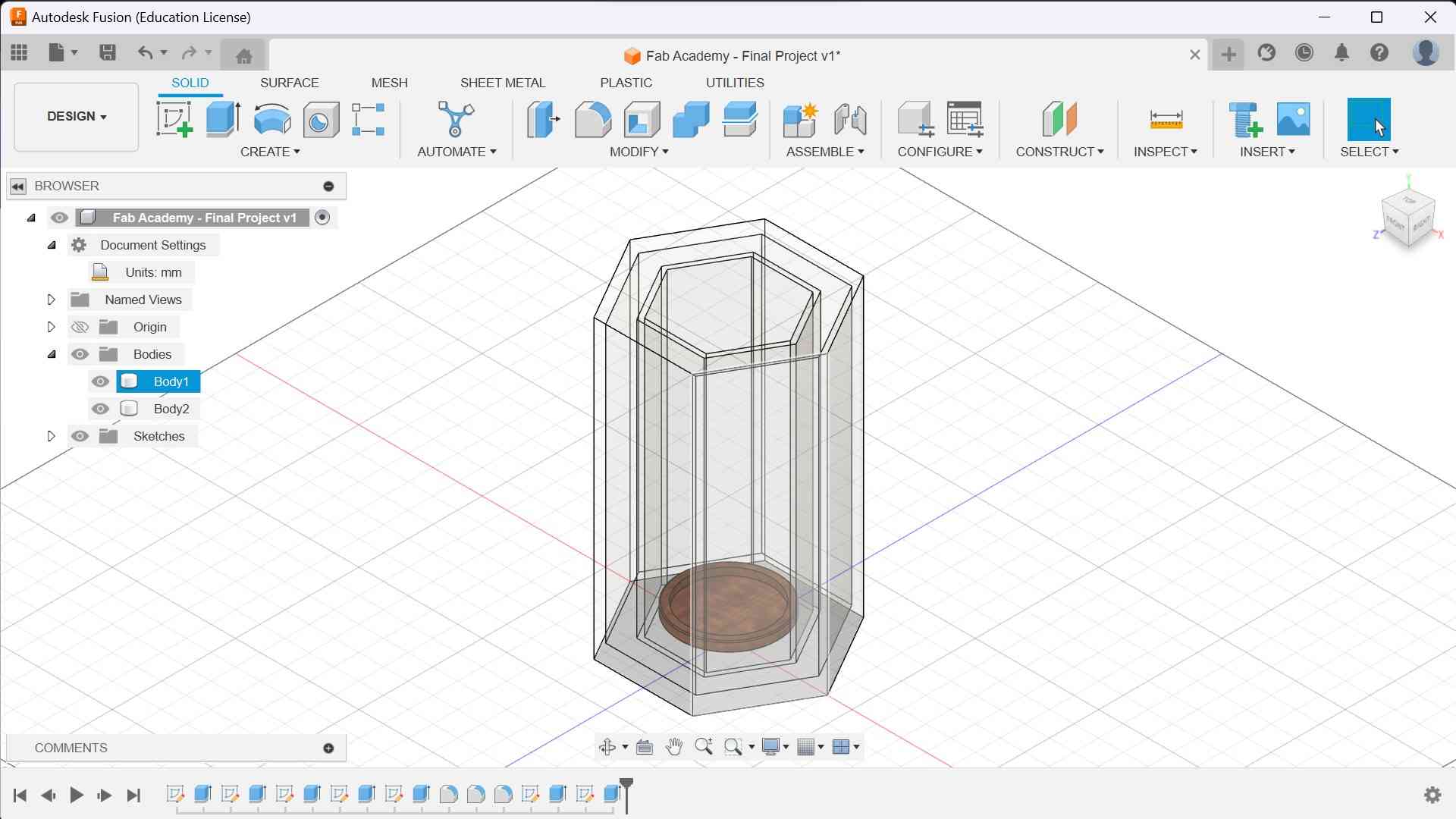
Following this, I created another smaller hexagon on top of this extrude and inversely extruded it downwards in order to make the body hollow.
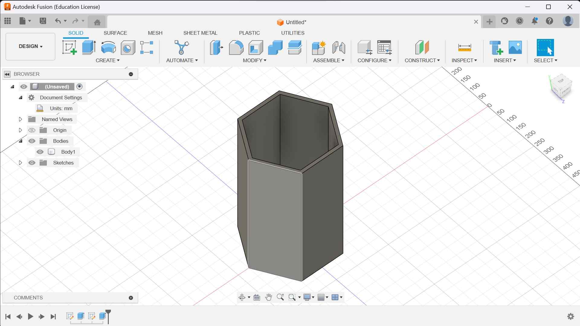
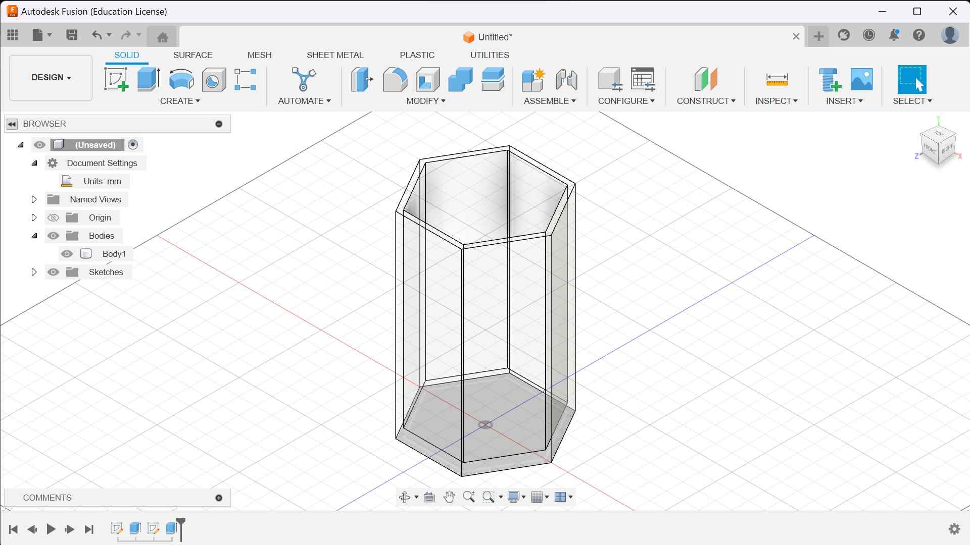
This created the outer shell of my fridge. From here, I used the drop-down menu to find the tab labled “appearances”. Then, I changed the material of my hexagonal shell to acrylic, which is likely what I will try to use for the final build. This also makes the extrude transparent, helping with later steps.
Now that I had the overall shape down, I could add the lazy susan on the inside. To do this, I first selected the previous bottom hexagon as the plane for my new sketch. Then, I added a square and extruded it to create the base of my lazy susan. I also changed the material of the lazy susan to wood so I could differentiate it from the acrylic shell. Then, on top of the base, I sketched a circle with diameter 200 mm and extruded it upwards. After filleting everything, I now had a (non-rotating) lazy susan model.
For the final part of this sketch, I simply added a roof over my entire model. After everything was done, this is how my final project model looked:
You can see the interactable version of this model below.
Fusion Reflection
Overall, I enjoyed using Fusion to create a model of my final project. I already had some experience with Fusion prior to this project, so it felt relatively easy for me to learn and use. One thing about Fusion which was very helpful while creating this model was the timeline at the bottom of the screen. It made it very easy to go back and edit some dimensions without having to restart the entire modelling process from that point.
Solidworks: Ball Bearing
After using Fusion to create a model of my final project, I wanted to try something different for my next CAD software. I initially wanted to create a normal bearing, but I eventually decided that that would be too simple. So, instead, I decided to create a ball bearing. After some searching, I found this simple guide which allowed me to get started.
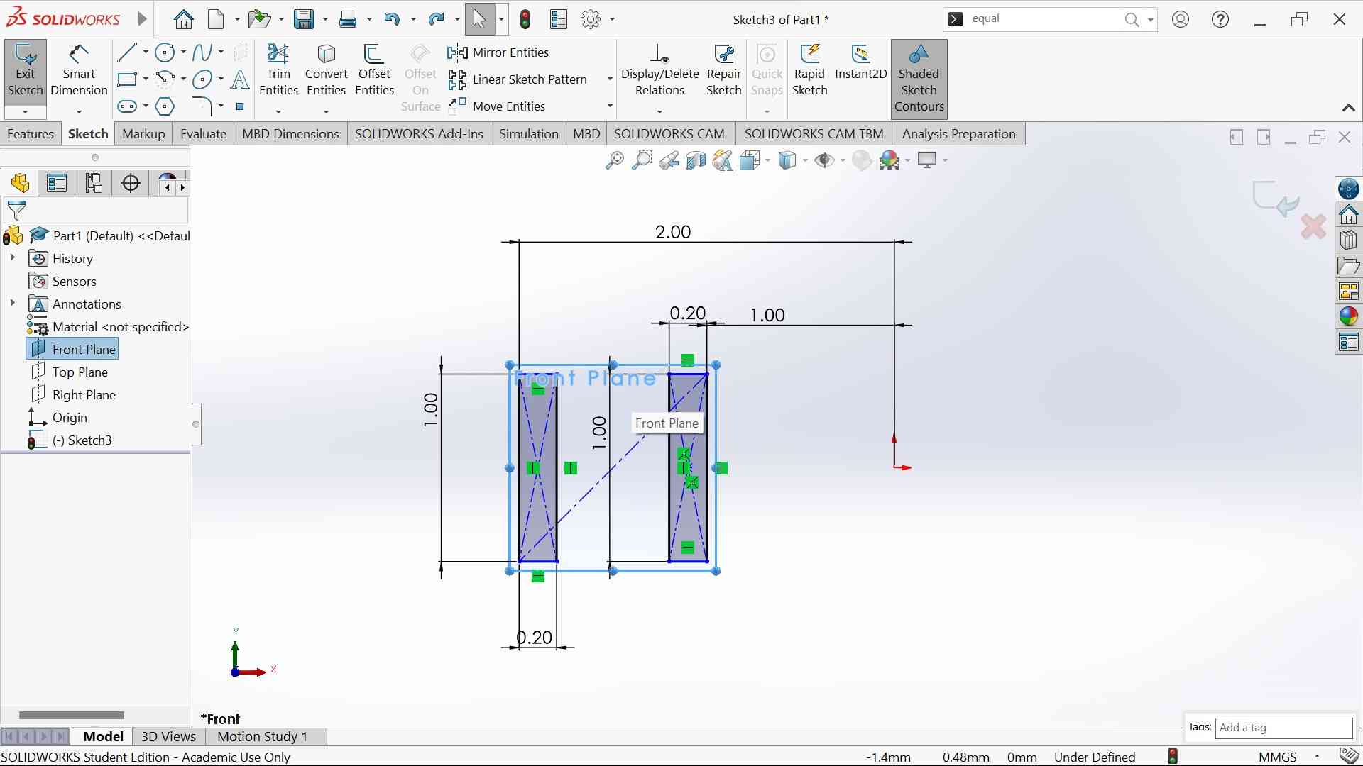
The first thing I did upon opening Solidworks was create a new part and start a sketch on the front plane. Then, I proceeded to draw two corner rectangles and defined them to the origin. For this model, I did not use any specific units of measurement and instead chose to use relative units. I assigned these two rectangles lenghts of 1 and widths of 0.20. Then, I dimensioned the close end of the first rectangle to be 1 unit away from the origin and the far end of the second rectangle was dimensioned to be 2 units away from the origin. After this, I drew a construction line diagonally from the top right of the first rectangle to the bottom left of the other, which will be useful in the next step.
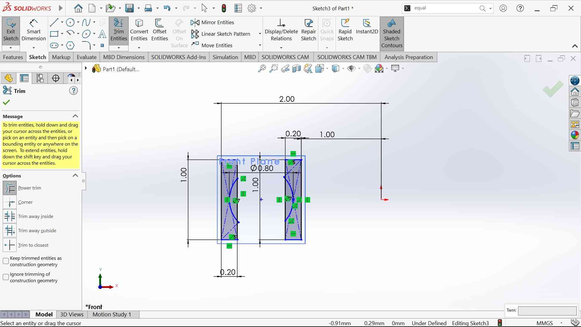
Following this, I created a center-point circle on the midpoint of the diagonal construction line and gave it a diameter of 0.8 units.
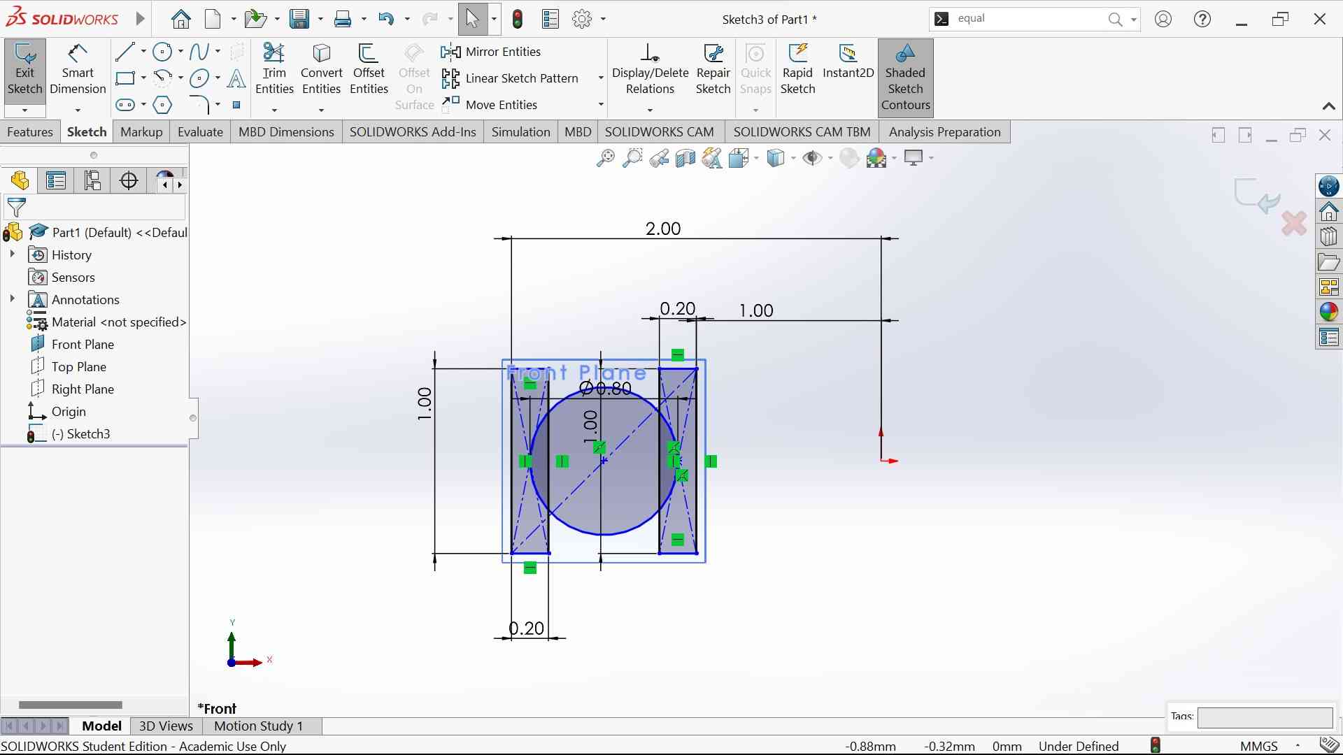
I then used the trim tool to remove the portion of the circle which was not contained by the two rectangles. The trim tool was very useful for this because it automatically deleted portions of the circle which were hanging in the open by themselves while also keeping the parts inside of the rectangles.
Now that the rectangles have been indented, I used the center-point arc function to create a 180 degree arc with a radius of 0.4 units and made it tangent to the indent on the right rectangle. I then connected the top and bottom of the arc with a line to create a half-circle plane.

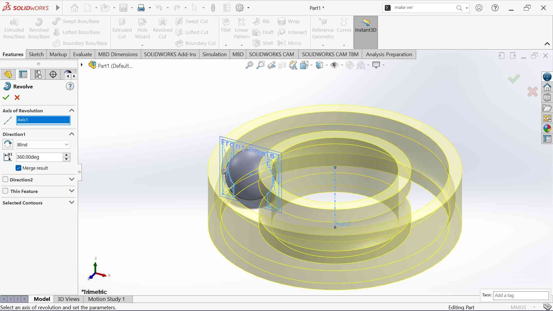
I was now done with the sketch and could move on to using the revolve function. The first thing I did after finishing the sketch was choose the half-circle plane I just made as the profile for the revolve, and I chose the vertical line I made as the axis.

I then proceed to use another revolve, but this time, I selected the two rectangles as the profiles. I then went back into my original sketch and created another vertical line straight through the origin. I selected this new line as the axis for the revolve. This created the outer part of my ball bearing.
After creating the outer shell of the ball bearing, I could finish the final step to create this model, which involved the use of circular patterning. I simply selected the circular pattern function, chose my first revolve, the ball, as the object, and created a 360 degree circular pattern creating 8 instances of my original revolve.
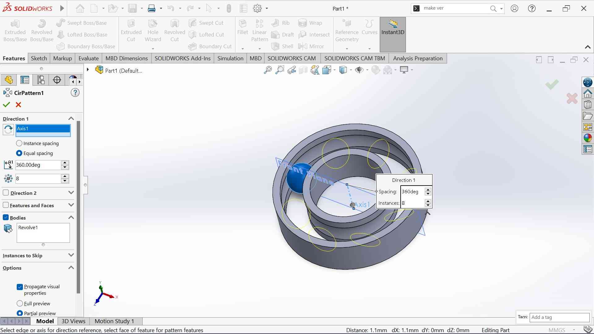
After doing this, I now had the final product!

Solidworks Reflection
I had never used Solidworks before creating this ball bearing, so its interface and tools were very new to me. I have to say that I found it more complicated than Fusion, with a more complex UI but also more intuitive tools. I think that, given more time to experiment with Solidworks, I could see it being more useful than Fusion. However, I did experience a few minor issues while using it. Namely, I found the camera harder to manuever than in Fusion, and I personally preferred the more basic UI of Fusion as well. Other than these complaints, however, Solidworks was a great CAD software to use, and I hope to continue using it in the future!
Onshape
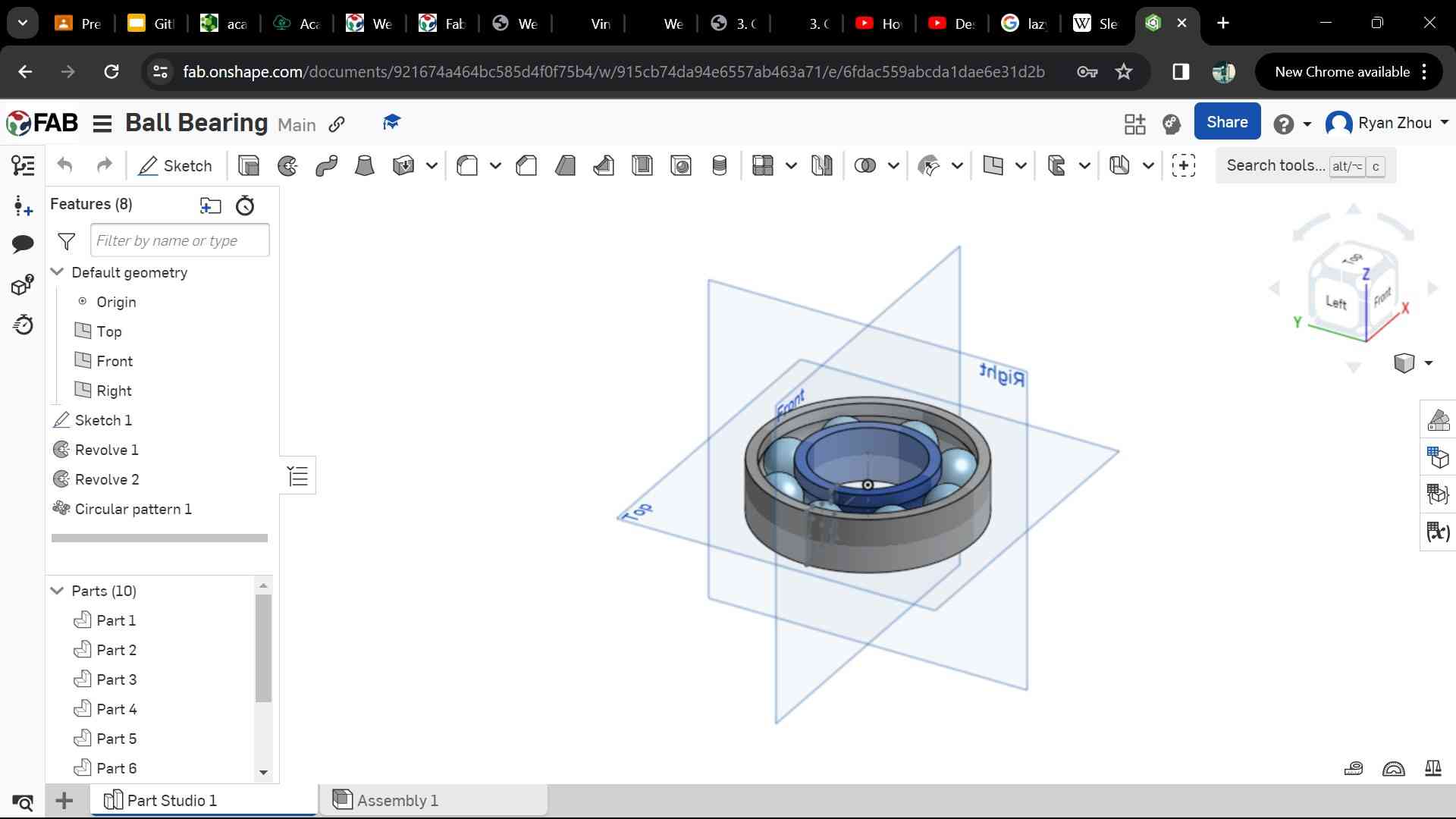
For my third and final 3D CAD software, I decided to choose Onshape. I have had some level of experience in the past, which helped me going into this, but that previous experience mostly had to do with creating assemblies and not actually creating my own parts. This meant that, although I had a good grasp on how Onshape worked, I wasn’t that familiar with how to create and design my own parts.
I decided to create the same part in Onshape as I did in Solidworks, which was the ball bearing. I followed the same step-by-step process to do this, so I did not add the same pictures as the previous section as I thought that would be redundant. Overall, the process went pretty smoothly, and the finished product is displayed below:
Onshape Reflection
Out of the three CAD softwares I have used so far, I would say that Onshape was definitely the easiest to learn. It is also the only free software out of the three I tried, which I think makes it very helpful for beginners. I found the UI very intuitive, and each of the different functions was very easy to differentiate. If you hover over any icon in the toolbar, Onshape creates a drop-down to tell you exactly what the icon does, which I found very useful whenever I didn’t know the use of a particular tool. The only downside to Onshape which I experienced was the lack of advanced tools compared to Solidworks and Fusion. This was to be expected as Onshape is free and open-source, but I still felt that there were many things that could be optimized better in Fusion or Solidworks due to the availability of such a large library of tools. Overall, though, Onshape was a very useful and simply CAD program that I will definitely continue to use in the future.
Back to Fusion: Ball Bearing
After creating ball bearings in both Solidworks and Onshape, I decided to go back and create one in Fusion as well. Again, I followed all of the same processes as I previously used. Because this was now my third time creating the ball bearing, I felt much more comfortable using the required tools and ended up finishing the model in only around 10 minutes. I have attached an interactive model of this ball bearing below.
2D Rastering: GIMP
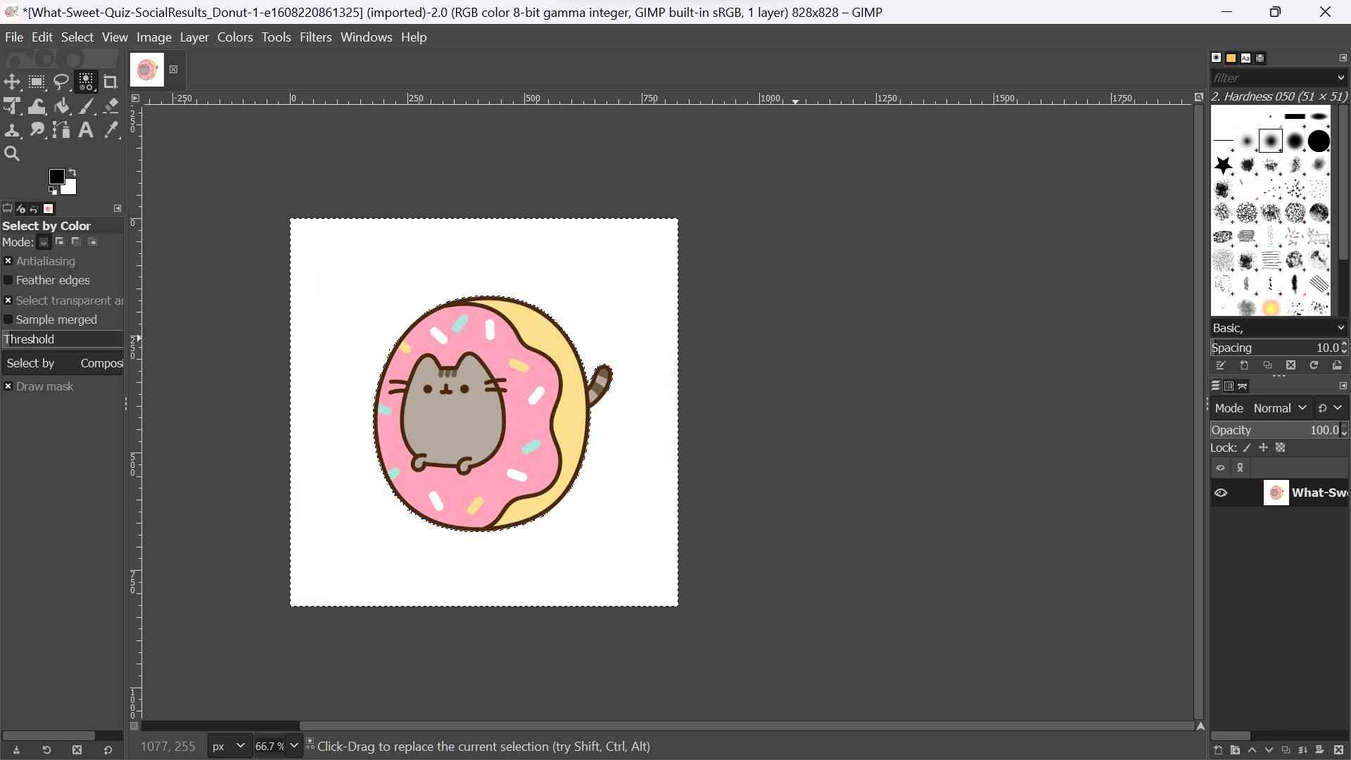
Now that I had experimented with a few 3D CAD softwares, I wanted to try using a 2D imaging application. Like many of my classmates from this year and in past years, I decided to download and use GIMP. GIMP stand for GNU Image Manipulation Program and it essentially allows you to perform simple manipulations on images in many different formats. I ended up choosing a picture of pusheen, a cartoon cat, to use for GIMP. The original image can be seen below.

As you can see, this image has a purple background, and my first goal was to remove it. In order to do this, I clicked on the “tools” tab at the top of my screen, went to the drop-down and clicked on “selection tools”, and chose the color picker. I then clicked on the background of my image. This tool allows you to select any pixels on the image with the same color as what you clicked on, so I was now able to hit the delete button to delete the background.
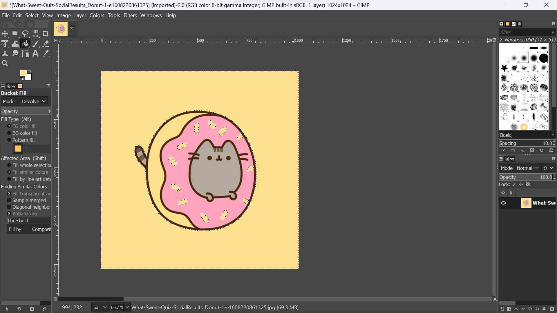
Now, I wanted to remove some of the colored sprinkles inside of the image. To do this, I again used the color picker, selected each of the individual sprinkles, and pressed the delete button. Alternatively, you can also use the eraser after selecting a color for the same result. If you use the eraser after selecting a color, the eraser will only erase that specific color, ignoring any other colors. I then filled in the now empty sprinkles with the same orange color that was on the right side of the image.

Finally, I used the color picker again, selected the now white background, and changed it to the same orange color as the sprinkes. Now that I was done editing the coloring of the image, I decided to resize it. To do this, I selecteed the “image” tab at the top of my screen and chose the resize image option. Then, I upscaled the size and graphical quality of my image and pressed confirm. Then, I went back to the image tab, and, this time, I chose the transform tool. I clicked on the horizontal flip option, which mirrored my image. The final result is shown below.
Reflection: GIMP
My first impression of GIMP is that it is a relatively simple software, allowing you to edit the coloring, size, and orientation of images very easily. The tool which I found most useful was the color picker, as it allowed me to choose specific parts of an image and only change that portion. I also found the fill tool useful, as it automatically changes the color of any fully contained shape. Overall, I would recommend GIMP to anyone looking for simple 2D image manipulation.
VR CAD: Gravity Sketch
During class this week, our teacher, Mr. Dubick, brought VR headsets with the app Gravity Sketch for us to CAD with. As you can see below, my classmates and I were pretty eager to try these out…
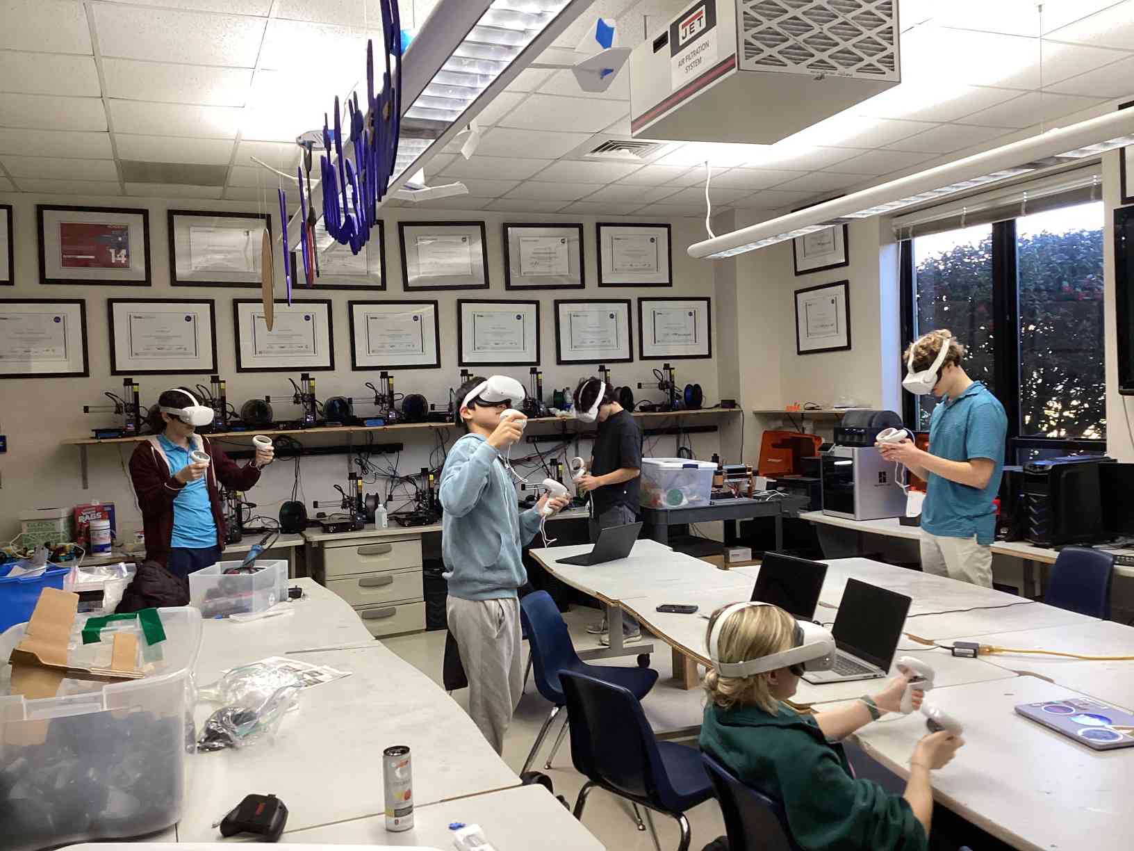 Richard(middle) getting jumpscared :D
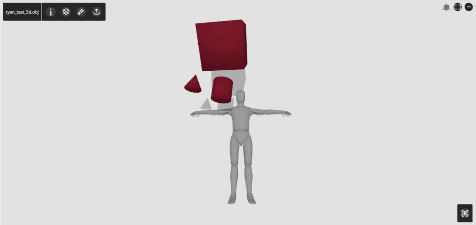
Moving on, Gravity Sketch is a VR CAD software which allows users to sketch and create objects in a virtual 3-dimensional space. Using this software, I created a 3d .obj file and managed to export it to landingpad.me, a website which lets me upload Gravity Sketch files directly to the cloud. Then, I downloaded the file onto my computer and created a Google Drive folder with the .obj file in it. Below is the workflow I used during this process:
- On home menu, click on LandingPad, login to engproj@charlottelatin.net without password
- Click on magic link
- Open the email account and click “Activate Magic Link”
- Create a 3D sketch
- Enter the menu by clicking the 3 lines button
- Go to the save and export tab that looks like a hard drive
- On the bottom, click the toggle under “save to device” until it says save to LandingPad
- Make sure the file is exported as an OBJ, welded and render is on
- When it has sent, your left hand will have a text saying “This file was sent to ___”
- Open landingpad.me on your computer
- Sign in using magic link again
- Export your file from landingpad.me onto your computer for personal use
- Unzip it and add it to a Google Drive Folder
You can see my test CAD below:
Reflection
Week 2 went pretty well for me overall. The 3D CAD portions went smoothly without many big issues except for one issue I encountered when creating the ball bearing in Solidworks, where my sketch was undefined even though I thought that I had added enough dimensions. My changes in GIMP also went very smoothly after I figured out how to navigate the interface. Here are the files for the final project model in Fusion and the 3 ball bearings I made.