Week 13. Networking and Communications
Group Assignment:
- Send a message between two projects.
Link to Group Assignment Page for this week.
Individual Assignment:
Disclaimer: All the Assignments and Documentations are done and written by me, however after writing it myself, some I pass it through chatGPT to fix my language and grammar.
- Design, build, and connect wired or wireless node(s) with network or bus addresses and local input &/or output device(s).
This week, I completed my assignment using the board I created and made during the electronics design week.
Connection
- Firstly, since the ESP32 comes with a pre-installed bootloader, manual loading is unnecessary.
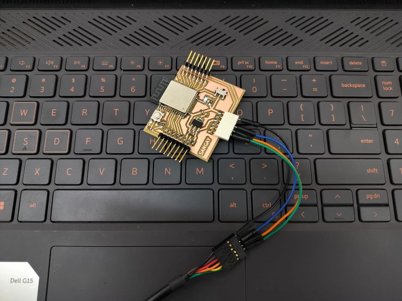
- Secondly, the ESP32 lacks support for USB protocol, therefore, I designed the board with an FTDI connector instead.
- For the FTDI connector, I utilized the VCC, GND, RX, and TX pins, keeping out CTS and RTS lines, which remained unconnected.

Connection for XIAO ESP32S3 (Sense):
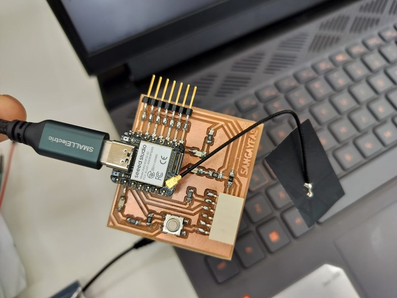
- To improve the WiFi and Bluetooth signal on the XIAO ESP32S3, you’ll find a separate connector for the antenna at the bottom left on the front.
- To install the antenna correctly, start by inserting one side of the antenna connector into the block, then gently press down on the other side to secure it in place.
- When removing the antenna, lift gently from one side, and it should come off easily.

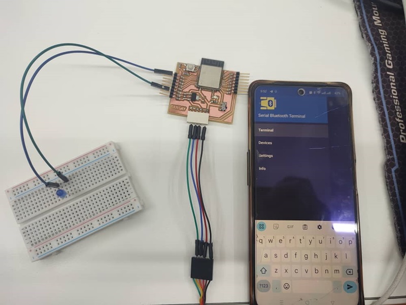
Connection for ESP32 device to control an LED via Bluetooth:
- To control the LED using Bluetooth, you’ll need a Bluetooth Terminal app on your smartphone.
- To begin, first need to pair your phone with the ESP32 Device.
- Once paired, you can use the Bluetooth Terminal app to send commands to turn the LED on and off.
So, first lets calculate resistor required for blue LED and current goes through the LED by refering parameter from datasheet:
Source Voltage = 3.3V (from ESP32 GPIO pin)
LED Forward Voltage = 3.2V
GPIO Pin Maximum Current = 40mA
Desired LED Current = 30mA
Blue LED Peak Forward Current = 100 mA

Using Ohm's Law (𝑉 = 𝐼𝑅)
R = (Vsource - Vled)/Iled
R = (3.3-3.2)/0.03 = 3.33 ohms

When connecting directly,

I = (V_eff/R_internal)
We know that internal resistance is very low,
the current would be limited by the effective voltage difference that is 3.3 - 3.2 = 0.1V.

therefore, small voltage difference (0.1V) across the LED would mean the current is very small.

Around its operating point (3.2V, 30mA),
we can use the dynamic resistance

Rd = (change in voltage / change in current) = 0.1/0.005
= 20 ohms
The dynamic resistance of LED can be approximated based on the I-V characteristics provided in the datasheet.

Current Calculation Without Resistor Using Dynamic Resistance:
I = 0.1 / 20 =0.005A = 5mA

Therefore, this current is within safe limits for both the LED (30mA maximum) and the ESP32 GPIO pin (40mA maximum).
After calculating resistance value I found out I need to use 3.33 ohms resistor for blue LED, but here in the lab we have min of 220 ohms resistor which when I used it gives very dim LED light, So I removed resistor to get brighter LED light. I understand that using an LED without a current-limiting resistor is not safe for the LED or the GPIO pins. However, I briefly used the LED without a resistor for a few seconds to make videos with a brighter light. I strongly recommend not doing this and always use a current-limiting resistor to protect your components and for consistent and controlled operation.

Programming
This week, I relied heavily on this example to complete my assignment. It’s a straightforward guide for setting up a web server using an ESP32 microcontroller.
Before uploading the provided code, I made sure to select the correct board, which was the ESP32 Dev Module, and the right COM Port in the tools menu. Once everything was set up correctly, I proceeded to upload the codes.
Wi-Fi Code:
/*********
  Rui Santos
  Complete project details at https://randomnerdtutorials.com
*********/

// Load Wi-Fi library
#include <WiFi.h>

// Replace with your network credentials
const char* ssid = "xxx";
const char* password = "xxxxx";

// Set web server port number to 80
WiFiServer server(80);

// Variable to store the HTTP request
String header;

// Auxiliar variable to store the current output state
String output15State = "off";

// Assign output variable to GPIO pin
const int output15 = 15;

// Current time
unsigned long currentTime = millis();
// Previous time
unsigned long previousTime = 0;
// Define timeout time in milliseconds (example: 2000ms = 2s)
const long timeoutTime = 2000;

void setup() {
  Serial.begin(115200);
  // Initialize the output variable as output
  pinMode(output15, OUTPUT);
  // Set output to LOW
  digitalWrite(output15, LOW);

  // Connect to Wi-Fi network with SSID and password
  Serial.print("Connecting to ");
  Serial.println(ssid);
  WiFi.begin(ssid, password);
  while (WiFi.status() != WL_CONNECTED) {
    delay(500);
    Serial.print(".");
  }
  // Print local IP address and start web server
  Serial.println("");
  Serial.println("WiFi connected.");
  Serial.println("IP address: ");
  Serial.println(WiFi.localIP());
  server.begin();
}

void loop(){
  WiFiClient client = server.available();   // Listen for incoming clients

  if (client) {                             // If a new client connects,
    currentTime = millis();
    previousTime = currentTime;
    Serial.println("New Client.");          // print a message out in the serial port
    String currentLine = "";                // make a String to hold incoming data from the client
    while (client.connected() && currentTime - previousTime <= timeoutTime) {  // loop while the client's connected
      currentTime = millis();
      if (client.available()) {             // if there's bytes to read from the client,
        char c = client.read();             // read a byte, then
        Serial.write(c);                    // print it out the serial monitor
        header += c;
        if (c == '\n') {                    // if the byte is a newline character
          // if the current line is blank, you got two newline characters in a row.
          // that's the end of the client HTTP request, so send a response:
          if (currentLine.length() == 0) {
            // HTTP headers always start with a response code (e.g. HTTP/1.1 200 OK)
            // and a content-type so the client knows what's coming, then a blank line:
            client.println("HTTP/1.1 200 OK");
            client.println("Content-type:text/html");
            client.println("Connection: close");
            client.println();

            // turns the GPIO on and off
            if (header.indexOf("GET /15/on") >= 0) {
              Serial.println("GPIO 15 on");
              output15State = "on";
              digitalWrite(output15, HIGH);
            } else if (header.indexOf("GET /15/off") >= 0) {
              Serial.println("GPIO 15 off");
              output15State = "off";
              digitalWrite(output15, LOW);
            }

            // Display the HTML web page
            client.println("<!DOCTYPE html><html>");
            client.println("<head><meta name=\"viewport\" content=\"width=device-width, initial-scale=1\">");
            client.println("<link rel=\"icon\" href=\"data:,\">");
            // CSS to style the on/off button
            // Feel free to change the background-color and font-size attributes to fit your preferences
            client.println("<style>html { font-family: Helvetica; display: inline-block; margin: 0px auto; text-align: center;}");
            client.println(".button { background-color: #4CAF50; border: none; color: white; padding: 16px 40px;");
            client.println("text-decoration: none; font-size: 30px; margin: 2px; cursor: pointer;}");
            client.println(".button2 {background-color: #555555;}</style></head>");

            // Web Page Heading
            client.println("<body><h1>ESP32 Web Server</h1>");

            // Display current state, and ON/OFF button for GPIO 15
            client.println("<p>GPIO 15 - State " + output15State + "</p>");
            // If the output15State is off, it displays the ON button
            if (output15State=="off") {
              client.println("<p><a href=\"/15/on\"><button class=\"button\">ON</button></a></p>");
            } else {
              client.println("<p><a href=\"/15/off\"><button class=\"button button2\">OFF</button></a></p>");
            }
            client.println("</body></html>");

            // The HTTP response ends with another blank line
            client.println();
            // Break out of the while loop
            break;
          } else { // if you got a newline, then clear currentLine
            currentLine = "";
          }
        } else if (c != '\r') {  // if you got anything else but a carriage return character,
          currentLine += c;      // add it to the end of the currentLine
        }
      }
    }
    // Clear the header variable
    header = "";
    // Close the connection
    client.stop();
    Serial.println("Client disconnected.");
    Serial.println("");
  }
}
Bluetooth Code:
/*********
  Rui Santos
  Complete project details at http://randomnerdtutorials.com
*********/

// Load libraries
#include "BluetoothSerial.h"

// Check if Bluetooth configs are enabled
#if !defined(CONFIG_BT_ENABLED) || !defined(CONFIG_BLUEDROID_ENABLED)
#error Bluetooth is not enabled! Please run `make menuconfig` to and enable it
#endif

// Bluetooth Serial object
BluetoothSerial SerialBT;

// GPIO where LED is connected to
const int ledPin =  32;

// Handle received messages
String message = "";

void setup() {
  pinMode(ledPin, OUTPUT);
  Serial.begin(115200);
  // Bluetooth device name
  SerialBT.begin("ESP32");
  Serial.println("The device started, now you can pair it with bluetooth!");
}

void loop() {
  // Read received messages (LED control command)
  if (SerialBT.available()){
    char incomingChar = SerialBT.read();

    if (incomingChar != '\n'){
      Serial.println("led_on to ON & led_off to OFF");
      message += String(incomingChar);
    }
    else{
      // Check received message and control LED output accordingly
      message = ""; // Clear the message buffer
    }
    Serial.write(incomingChar);


    if (message =="led_on"){
        Serial.println("led must be on now");
        digitalWrite(ledPin, HIGH);
      }
    else if (message =="led_off"){
      Serial.println("led must be off now");
      digitalWrite(ledPin, LOW);
      }

  }
  delay(20);
}
Networking & Communications
- The given code sets up an ESP32-based web server that can be controlled over WiFi.
- It connects to provided WiFi network credentials and then listens for incoming client connections.
- When a client connects, it reads HTTP requests from the client and responds accordingly.
- The server controls GPIO pin 15 (integrated LED), allowing clients to turn it on or off via a web interface. It generates an HTML page displaying the current state of GPIO 15 and provides buttons to toggle its state.
I also tried out the same code by editing GPIO Pin to 43 with XIAO-ESP32-S3 board, and it also worked perfectly.
- In the Bluetooth code, it sets up an ESP32 device to control an LED via Bluetooth. It initializes the BluetoothSerial library, checks if Bluetooth is enabled, and defines a constant for the LED pin.
- And in the setup function, it define LED pin as an output followed by serial communication, and begins Bluetooth communication with the device name “ESP32”.
- In the loop function, it continuously reads incoming messages over Bluetooth to turn LED on or off which controls the LED accordingly.