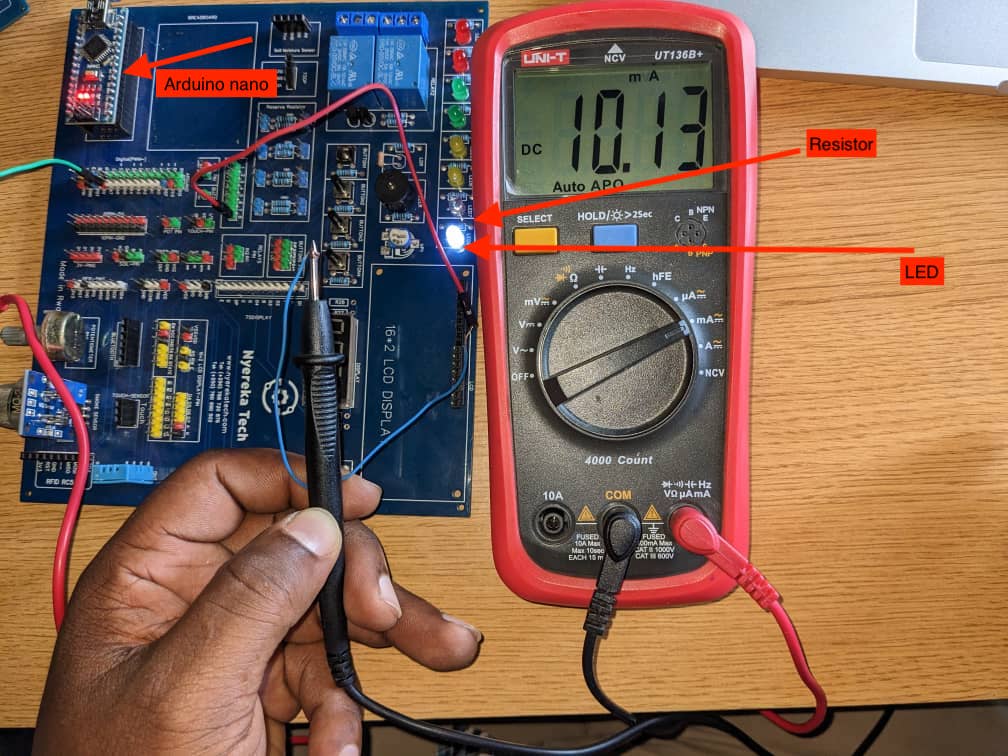
For this assignemnt, we want to test the current provided by atmega328p which os arduino uno board. the arduino uno board we have is embedded with another development board tht has many sensors and actuators and even built-in LED that can be used for beginners in embedded programamming. lets test ohms law and how it is applied on microcontrolles
Ohm's law is a fundamental principle in electrical engineering that relates the current, voltage, and resistance in an electrical circuit. It states that the current flowing through a conductor between two points is directly proportional to the voltage across the two points, and inversely proportional to the resistance between them. The mathematical equation for Ohm's law is:
I = V / R
where I is the current in amperes (A), V is the voltage in volts (V), and R is the resistance in ohms (Ω).
This equation can be rearranged to solve for any one of the three variables, depending on what is known or being measured in the circuit. Ohm's law is commonly used to calculate the voltage, current, or resistance in a circuit, and is a fundamental principle in understanding the behavior of electrical circuits.
what is a multimeter?
A multimeter, also known as a volt-ohm meter or VOM, is a versatile electronic device that can measure several electrical properties of a circuit. It typically measures voltage, current, and resistance, and may also include additional features such as continuity testing and diode testing
Arduino nano specs
| Microcontroller | ATmega328P |
|---|---|
| Operating Voltage | 5V |
| Input Voltage (recommended) | 7-12V |
| Input Voltage (limits) | 6-20V |
| Digital I/O Pins | 14 (of which 6 provide PWM output) |
| Analog Input Pins | 8 |
| DC Current per I/O Pin | 20 mA |
| DC Current for 3.3V Pin | 50 mA |
| Flash Memory | 32 KB (ATmega328P), of which 2 KB used by bootloader |
| SRAM | 2 KB (ATmega328P) |
| EEPROM | 1 KB (ATmega328P) |
| Clock Speed | 16 MHz |
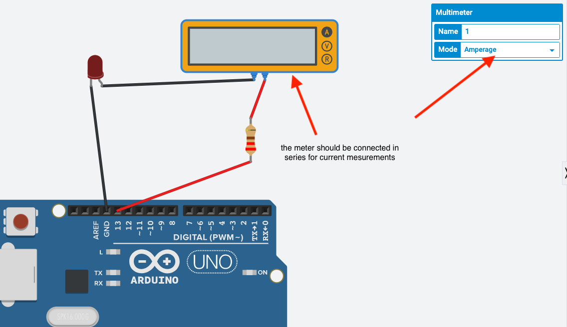
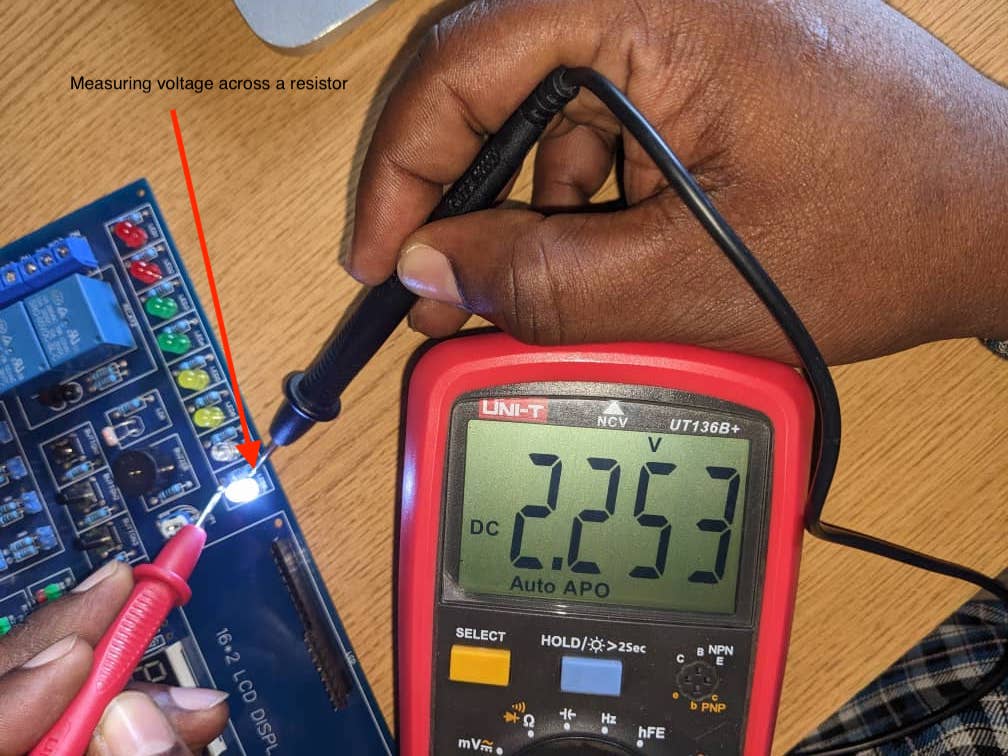
From that table above , i wanted to test whever the the output voltage of the microcontroller on any digital pin is 5V and also test the current that is offering when we supply the voltage to the LED and limiting resistor
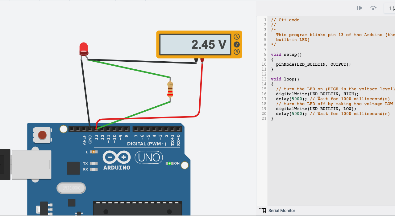
Here you see that i am measuring the voltage accrss the resistor. when a pin goes high, the multimeter reads 2.45V and we know that the pin outputs 5V , SO why 2.45V instead of 5V? Because the rest is the forward voltage drop of the diode

The above picture shows that the total voltage of pin 13 I/0 is 4.44V which is different from theorical voltage which is 5V. The drop on resistor is 2.45V and the drop on LED is 2V . our simulation is perfect . lets now test the current
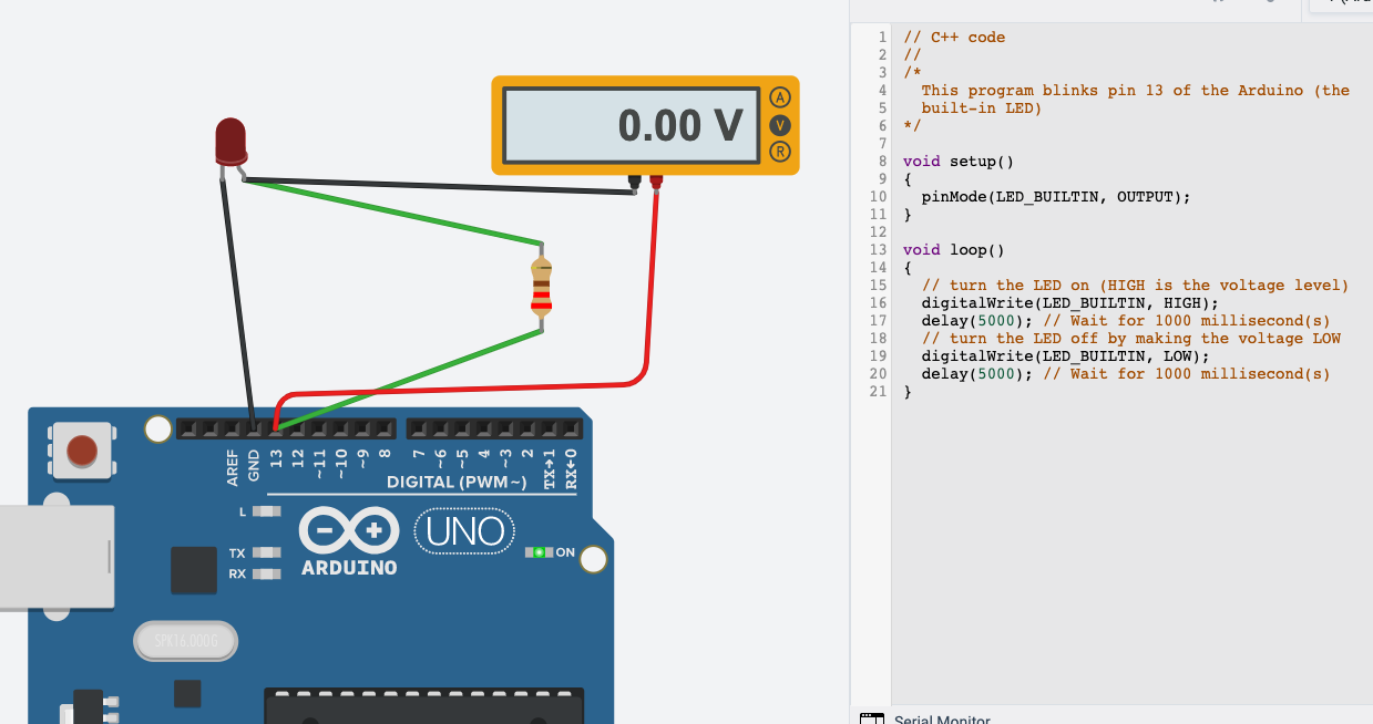


Now lest measure the I/0 voltage


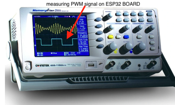
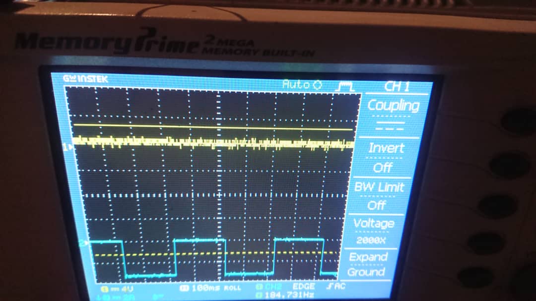
The following experiments is very simple. just checking the waveform of generated pwm signal on pin 30 of esp32
the following is the code used for testing

