Electronic Design
Group assignment:- Use the test equipment in your lab to observe the operation of a microcontroller circuit board (as a minimum, you should demonstrate the use of a multimeter and oscilloscope)
Individual assignment:Observe the operation of a microcontroller circuit board
Neil’s "Hello.HC-SR04"
The HC-SR04 Ultrasonic Shield utilizes ultrasonic soundwaves to determine distance from 2cm to 400cm with an accuracy of 3mm. Five volts on the Trig pin for at least 10 µs will trigger an 8 cycle, 40kHz sound pulse. If there is any object within range in the path of the pulse, an echo pulse will be bounced back. The HC-SR04 will give the time in microseconds it took for the soundwave to make a complete loop to and from the object on its Echo pin.
Check operating voltage
Multimeter
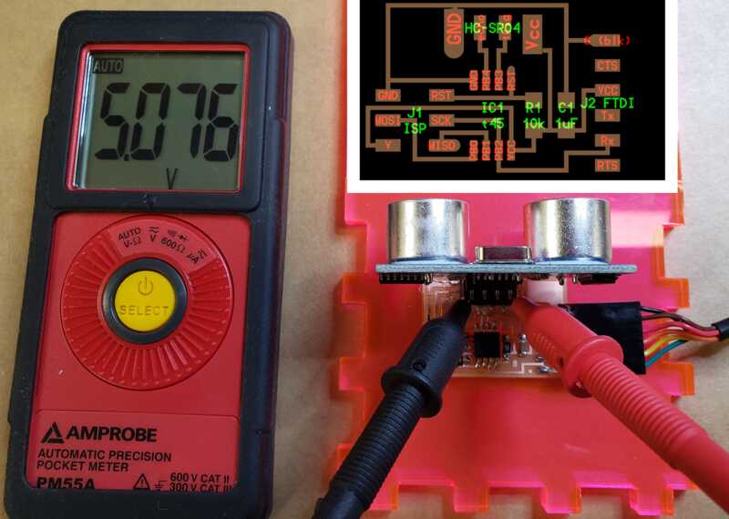
- AMPROBE PM55A
notes: indicate what it was plugged into
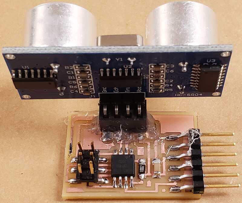
Ths Hello.HC-SRO4 board is connected to a USB port of a laptop via ftdi and the voltage at the GND and VCC points reads 5V.
Check noise of operating voltage
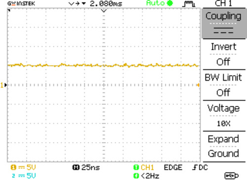
I started with 5V DC signal on 25ns per division time scale.
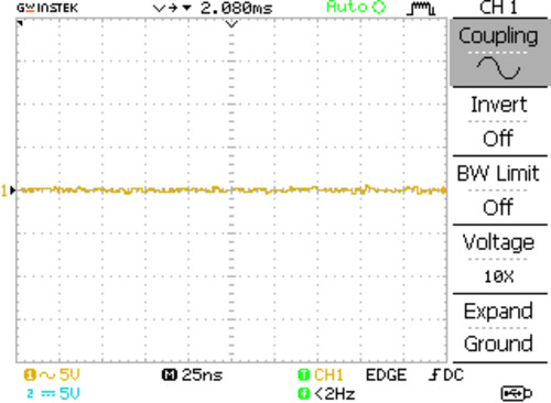
I changed the coupling to show only the AC noise.
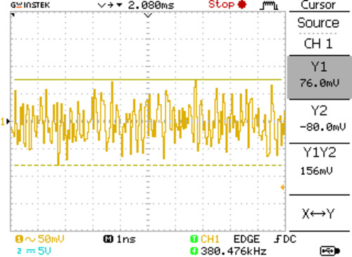
I lowered the voltage scale to 50mV and the time scale to 1ns to increase resolution.
The capture shows roughly 156mV peek to peek of AC noise.
Interpreting a data signal
Oscilloscope
- GwInstek GDS-1152A-U
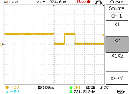
Below is a scope capture of serialized bits from the Hello.HC-SR04 Sonar board on the Rx pin at 9600 Baud.
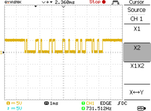
At 9600 baud, each bit is approximately 1/9600 or 104µs wide on the scope. If I set my time division to 100µs, this would make it easier to make distinctions between individual bits. Each byte of data also carries a start and stop bits along with the 8 data bits. This makes each byte 10 bits long.
Design a development board to interact and communicate with an embedded microcontroller
Board: inspired by Neil's t45-echo
Concept:
Connect to the board via serial and send a message. The microcontroller will then process the message into Morse Code and flash the message via the LED.
Components List:
- 1 x ATtiny45
- 1 x 1 kΩ resistors
- 1 x 100 Ω resistors
- 1 x 10 kΩ resistors
- 1 x 1µF capacitor
- 1 x LED
- 1 x ftdi connector
- 1 x (2x3) pins
- 1 x B3SN-3112P tactile switch
Select and use software for circuit board design
Updated to reflect lessons learned in Electronics Production
The design rules
- Design Rules:
    - Tool: 1/64 end mill
        - Minimum trace width: 0.004 in
        - Minimal clearance: 0.016 in
    - Tool: 0.10" end mill
        - Minimum trace width: 0.004 in
        - Minimal clearance: 0.011 in
- Parameters used in this design:
- Tool: 1/64
- Trace width: 0.010 in
- Clearance: 0.016 in
Demonstrate workflows used in circuit board design
Software: Eagle 9.6.2
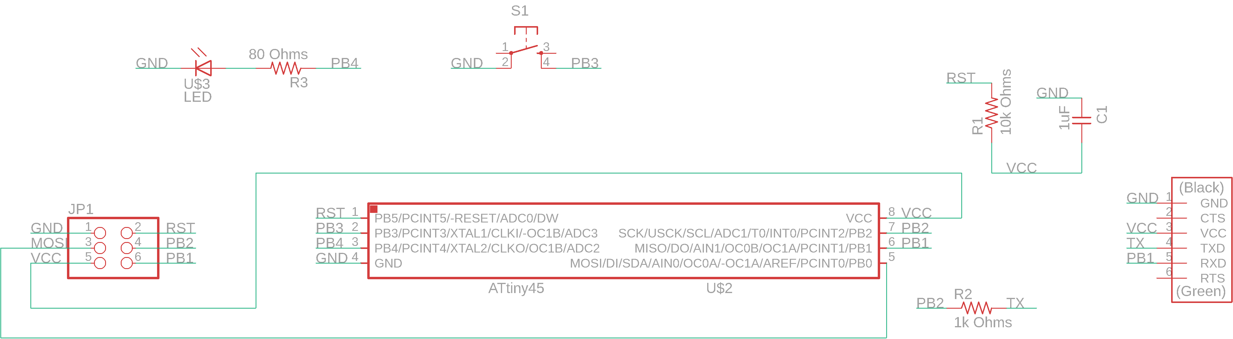
I started with Neil's t45-echo board as the base. As stated earlier, the concept is this:
1. Connect to the board via serial (pyserial works well)
2. Type out a message in 20 lowercase characters or less (punctuation and uppercase was not included)
3. Press ENTER
4. Press the button on the board (Starts tapping out morse code on the LED and screen)
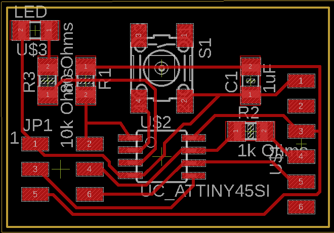
The first thing I considered was whether there are enough pins available to drive the LED and button. There are 2 pins still available on the t45, PB3 & PB4. As shown here, I assigned LED to PB4 and back to ground. The button is connected to PB3 and ground.
Routing traces
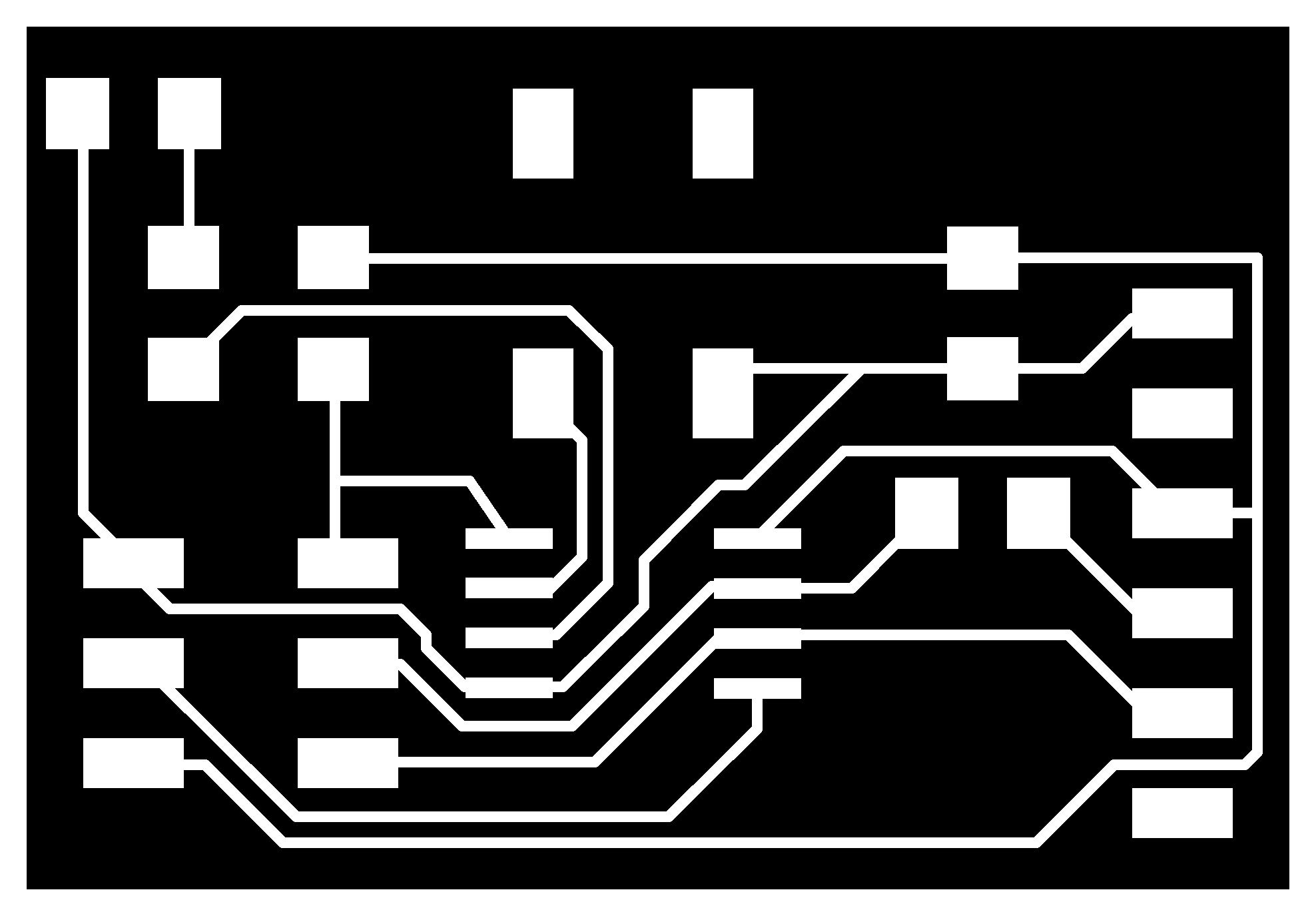
For me, autorouting has been a good place to start with placing my traces. I'd adjust component placement, autoroute again and manual reroute until I get the traces in a usable configuration. This is the final board layout.
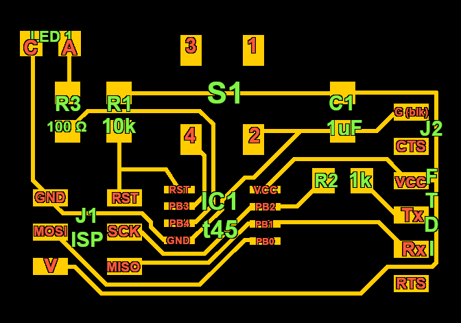
I found the images that Neil makes to show the placement of components very helpful so I made a similar image.
Finally, I used the rectangle tool to create the outside dimension of the board on the Dimensions layer. When exporting, I hid all layers except the "Top" and "Dimensions" layers and set the image to monochrome with a resolution of 1500 dpi.
Eagle was quite challenging to learn. I referred to a number of online sources and started over several times before I grasped enough to complete the assignment. This consumed a lot of time and because of the aforementioned reasons, I failed to take screenshots during the actual process.
Downloads
[For reference, a link to Neil's hello world t45-echo code ]