Computer Controlled Cutting
Group assignment:
Individual assignments- Design, lasercut, and document a parametric press-fit construction kit, which can be assembled in multiple ways. Account for the lasercutter kerf
- Cut something on the vinylcutter
Characterize your lasercutter
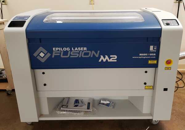
The laser cutter is the 75 watt CO2 Epilog Fusion M2. The bed size is 32"L x 20"H.
Testing
In each of these tests, the setting not being tested left at its nominal value.
Test material:
- Cardboard
Nominal cut settings:
- Speed: 13%
- Power: 50%
- Frequency: 5%
- Focus: 2" from material surface
Speed
-
@23 : When set too high, that is above 13 in my testing, the laser failed to cut through the cardboad.
-
@1: When set very low, there wasn't any noticeable difference other than it takes longer to cut.
Power
-
@100: When set too high, above 50%, there wasn't any noticeable difference. The laser cuts through the material just the same but only uses more power to do so.
-
@10: When set too low, the laser failed to cut through the cardboard.
Rate (or frequency)
-
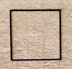
@100: When set too high, there wasn't any noticeable difference. The laser cuts through the cardboard.
-
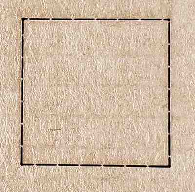
@1: When rate of the laser pulses was set too low, it resulted in a perforated outline and so it didn't completely cut through the material.
Focus
The focus gauge focuses the laser in at 2 inches
-
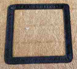
<2" : At a distance under 2 inches, the unfocused laser left a thick, charred outline that cut into the cardboard but not through the cardboard.
-
>2" : At a distance more than 2 inches, the unfocused laser left a broad, charred outline on the surface of the cardboard but didn't cut into or through the cardboard.
Kerf
The following is the approach I used to determine the laser's kerf:
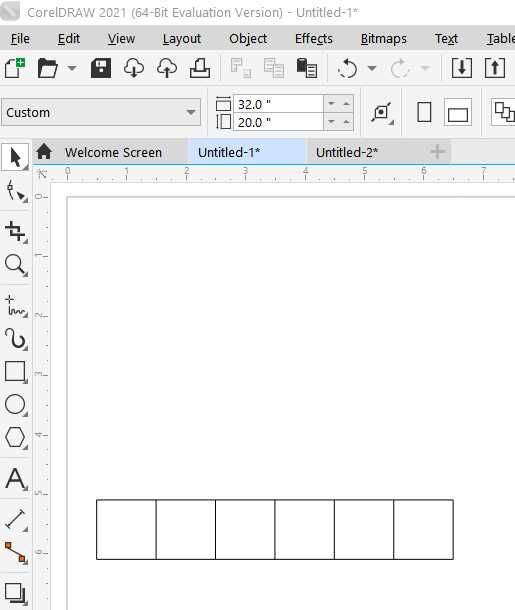
- Using 0.19" cardboard, cut a series of 6 squares
- Line up the squares and measure the combined length
- Measure the negative space
- Do the math to determine the kerf
Using the rectangle tool in CorelDraw, I drew 6 squares with a line thickness of 0.004" (0.101 mm) or less, which is considered hairline thickness. Hairline thickness tells the lasercutter these are vector toolpaths, not raster and therfore to cut, not engrave.
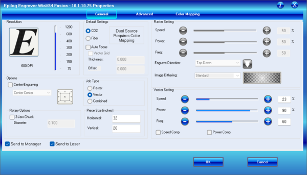
I used following settings on the laser cutter for this job:
- Speed: 23%
- Power: 90%
- Frequency: 60%
- Focus: on the material surface
One thing to note is that in this process to determine the laser kerf, the laser was focused on the surface of the cardboard. I believe this is important because the waist of the beam, which is the thinnest part of the laser, is on the surface of the material, so the kerf is
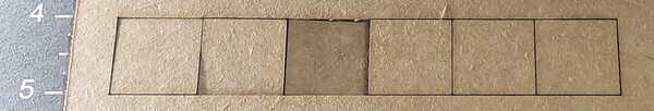
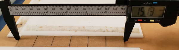
I extracted the squares, lined them up side by side to measure their combined length.
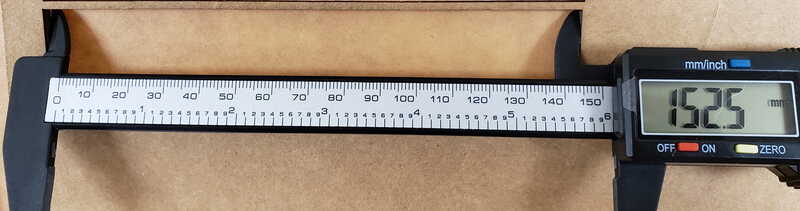
Next, I measured the length of the negative space left behind.
The lateral negative space the squares left behind will be longer than the combine length of the squares. Subtracting the combined length from the negative space will give me the total kerf width.
Combined length measurement: 151.3 mm
Negative space measurement:  152.5 mm

Subtract the combined length from the length of the negative space:
  152.5 mm - 151.3 mm = 1.2 mm
I have the total kerf width, however, there are 7 edges. I need to know the kerf for one edge. To get that number, I divide the total kerf by the number of edges, which again, is 7.
Divide the difference by the total number of edges, which is 7 in this case:
  1.2 mm / 7 (total number of edges: 6 squares - 7 edges) = 0.1714 mm
The kerf in milimeters is 0.1714. I measured in milimeters for better accuracy since I'm dealing with such small measurements. To convert to inches, I divide 0.1714 by 25.4.
Divide by 25.4 to convert milimeters to inches:
  0.1714 / 25.4 (divided by 25.4 to get inches) = 0.0067 in

  My kerf size is 0.1714 mm (0.0067 in)
I went througth this process a second time for accuracy's sake and the resulting kerf was 0.1857 mm (0.0073 in).
If I average the 2:

(0.1714 mm + 0.1857 mm)/ 2 = 0.17855 mm

I get a kerf size of 0.17855 mm (0.007 in).
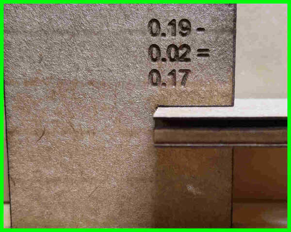
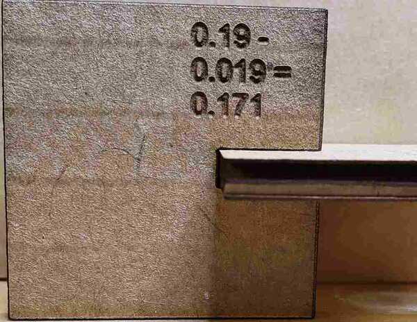
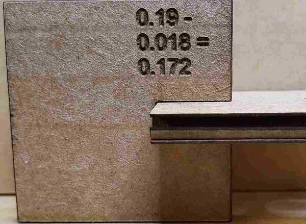
Joint Clearance:
Here I ran a test to determine the amount of clearance, or compression in this case, to acheive a good compression fit joint. I made each slot slightly smaller than the thickness of the cardboard (0.19 in).
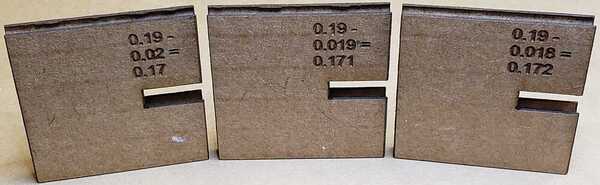
I found that undersizing the slot by 0.02" which yields a slot width of 0.17" makes a good compression fit.
Design, lasercut, and document a parametric
Design Software: Fusion 360
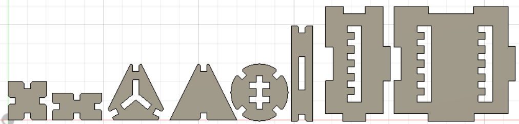
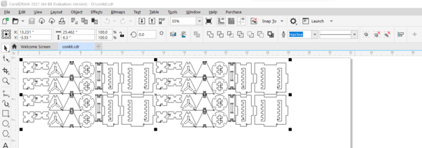
Unsure where to begin with a construction kit, I started with basic shapes, square, rectangle, triangle, circle, added slots and fingers, and expanded from there. Here is an overview of the parts that were created in this kit.
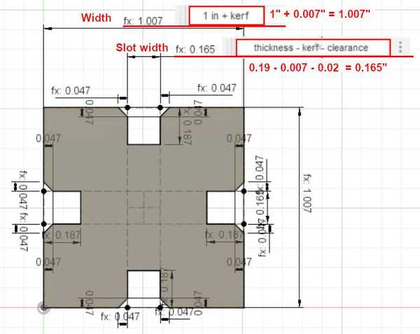
The laser cuts directly on the toolpath thus altering the dimensions of the project, so has to be accounted for in the design phase. Take for example the piece in the image below where the "Width" is 1.007". It's dimensioned to be 1" wide. The laser kerf will decrease this by 0.007". To compensate, I added a full kerf to the width on the front end which results in a width of 1.007". When this is cut on the laser cutter, the width will be 1". This same approach was applied to the height.
As for the slots, they are based on the thickness of the cardboard, which is 0.19". The laser kerf increases this width. This will cause the slots to be far too wide. To compensate, I have to subtract the kerf on the front end. Additionally, to get the right compression, I also need to subtract the clearance, which is another 0.02", from that already kerf adjusted 0.19 inch. The resulting width of the slot is 0.165". When this is cut on the laser cutter, the width will be 0.17", which is the thickness minus the clearance (0.19" - 0.02").
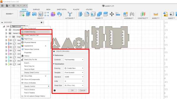
To export this construction kit, right click on name of the project > click "create drawing" > Ok.
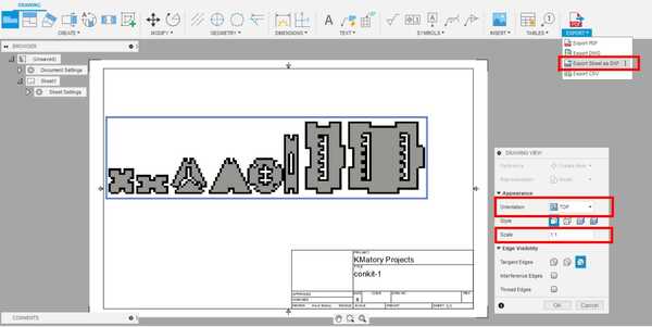
I chose the "TOP" orientation and "1:1" scale. Under export click "export as dxf".
Corel draw - Imported the DXF file into Corel Draw and set the line thickness to "hairline" for cutting.
Sending the print job to the laser cutter
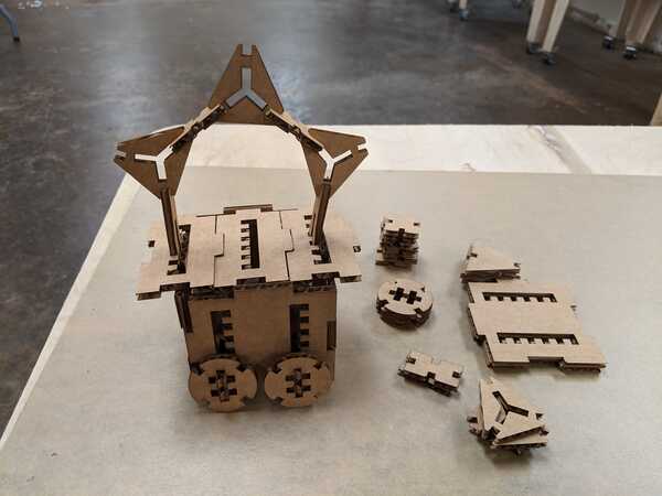
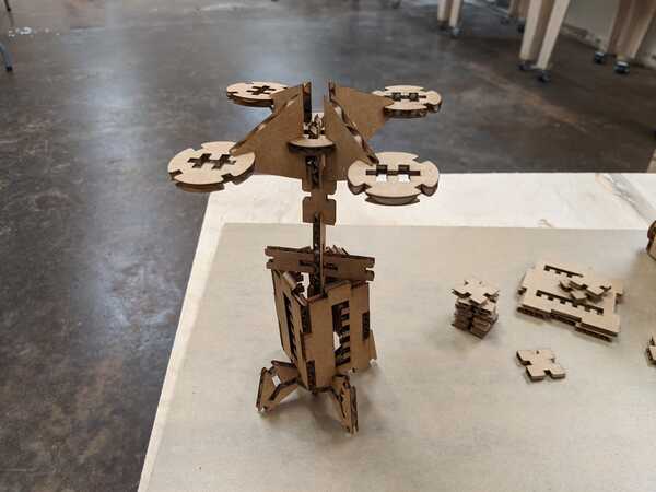
A couple of structures made with the kit

Cut Something on the Vinylcutter
I started with installing the appropriate drivers and software. Once up and running, I made some test cuts with the CAMM-1 GS-24 to determine the appropriate cut depth and speed.
Below is how I set up and tested the machine before I cut my image.
1) Load and guide the material into the feeder
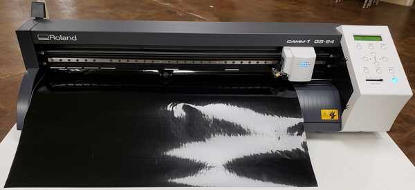
2) Set the pinch roller on the material according to where you want to cut and engage the loading lever to clamp the pinch rollers down
3) Power on the device
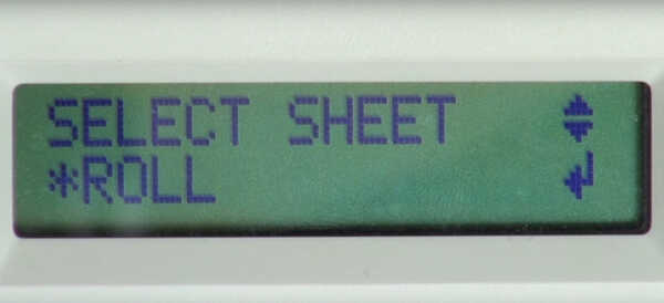
4) The machine will display "SELECT SHEET: a Roll, Edge or Piece" (Roll in my case). Select with up,down arrows and press "Enter"
- The machine runs the carraige across the length of the feeder and scans the sheet and the location of the rollers
- The machine prints on the LCD screen the distance of the rollers from each other, the cut force that will be used, and the offset
- Using the arrows, move the vinyl forwards or back until it is where you want the edge to be in relation to the cutter head
- Once the vinyl is set, press and hold the "Origin" button to set the origin
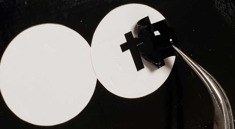
- Press and hold "Test" to perform a test cut
I performed several test cuts until I was able to shear away the surrounding vinyl without pulling up the surrounding pieces.
Note: The force, speed or offset can be changed by using the arrow keys to navigate.
- MENU
- Scroll down to CONDITION
- Right Arrow to select CONIDITON
- Scroll up or down to either SPEED, FORCE or OFFSET
- Right Arrow to select
- Use up, down arrow to modify
- Press "ENTER" to save changes
The Vinyl Cutter was already set with a Pen Force of +2. When I ran my test cut, I found that these settings worked well with the Pen Force at +2.
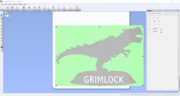
Setting Up the Design in CutStudio
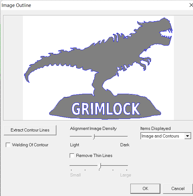
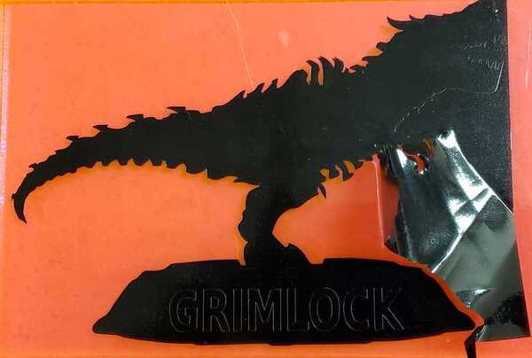
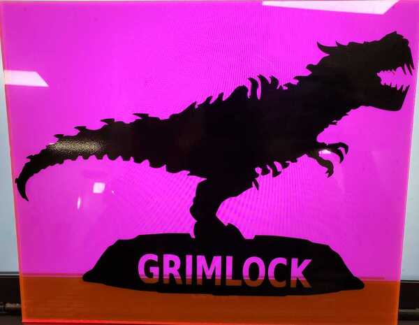
I took an image of the movie Grimlock statue from the Sideshow.com website and using Krita, I simplified it by making a silhouette. I also added some lettering on the base and saved it in a vector format. Download the original image here.


To create the outline to cut:
Import the design into CutStudio
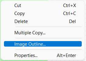
Right click -> "Image Outline"
Click "Extract Contour Lines"
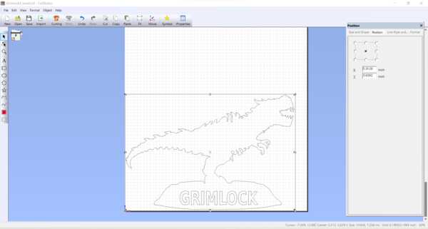
I moved the outline over to the side, selected and deleted the original image.
Click "Move to origin"to align the outline to the bottom, left corner of the screen, which represents the front, left corner of the material coming through the machine feeder.
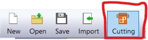
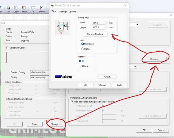
From the menu bar, click Cutting
Lastly, import the width dimension set earlier using the pinch rollers on the machine.
Click "Change" > "Change" > "Get from Machine"
Then Click "OK" on all screens to send to the CAMM-1 GS-24
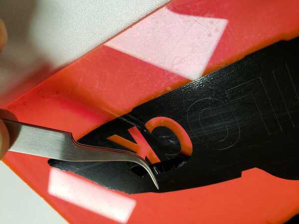
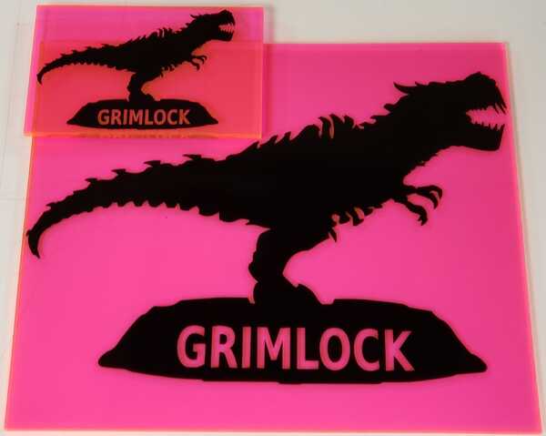
I laid the entire piece out on an acrylic sheet and then weeded by sheering the unwanted material.
I started with a smaller version to practice with before making the larger version.
Downloads
* Cutstudio does not export and only saves as a CST file, so here is the PNG file I used. *
