Computer-Controlled Machining
Group assignment:Individual assignment:CNC Machine:
- ShopBot
Toolpathing software:
- Vectric VCarve
Do your lab's safety training
- I've completed my lab saftey training.
Test ... for your machine
Runout
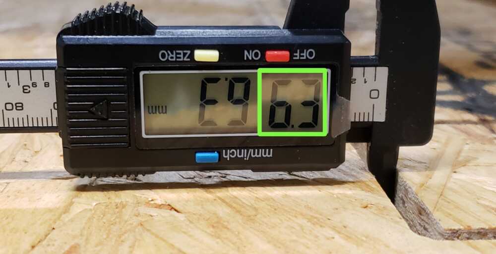
I took the opportunity to take measurements to check the runout while testing for alignment.
Kerf measurement: 6.3 mm
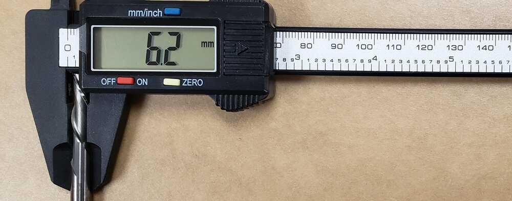
Tool measurement: 6.2 mm
6.3 (kerf)
- 6.2 (tool diameter)
= 0.1 mm / 0.003937 in of runout
Alignment
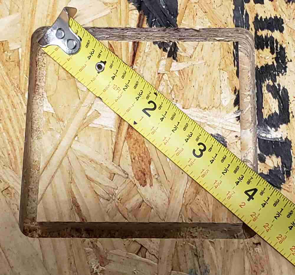
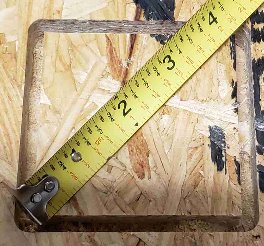
The measurement is 4.25 inch, corner to corner, in both directions.
Tool
- 1/4 in. down cut
Speeds
- 14000 rpm
Feeds
- 3 in. / sec
Toolpaths
- Software:
- Vectric VCarve
The method of toolpathing for the test is the same as for the Make Something Big project. For more details, please see the Toolpathing for Shopbot section.
Fixturing
I used screws for fixturing during the test. This is covered in more detail in the "using fixtures" section of the Make Something Big project. I used an additional fixture type during the project so also see "kerf filler fixtures" for more details.
Materials
- 3/4" OSB Plywood was used for testing.
- 3/4" Birch plywood for Make Something Big
Make Something Big
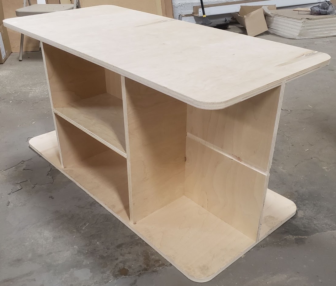
Coffee Table
- dimensions: 46" L x 21" W x 21.7" H
Materials
- 3/4" Birch plywood (0.70 in)
- 0.19" cardboard
Software
- Autodesk Fusion 360
- VCarve Pro - ShopBot Edition 9.5
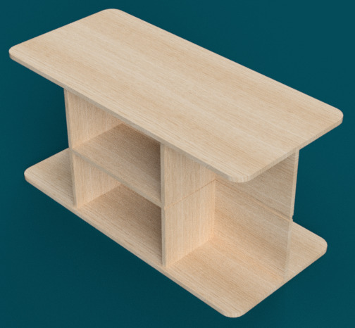
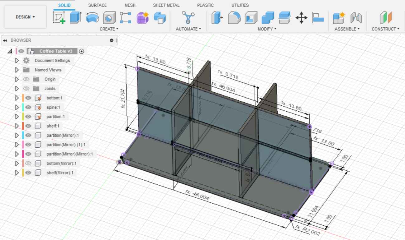
Rendering
This is rendering of the table made held together with press fit joints.
Testing Joints
Before I start designing, I need to carry out a compression test with the plywood I'm using to determine the tolerance needed for effective joints. The tolerance will tell me how much clearance or overlap needed in the joints for the desired fit.
Since I'll make a scale model first from cardboard, I'll also need to keep in mind the kerf of the laser cutter already determined in Computer Controlled Cutting as 0.007 inch. The model is just to further reveal any problems with my design, so I won't be simulating the joints and therefore, the tolerance for cardboard joints isn't needed.
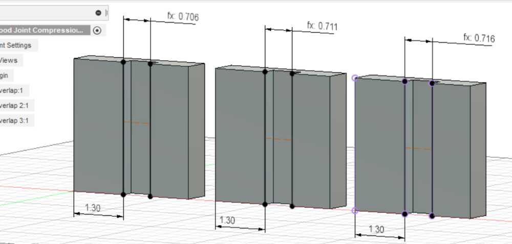
For this test, I modeled 3 blocks being sure to account for the runout. Each block has a channel that is 0.70" wide, which is the thickness of the plywood. An additional width of 0.01", 0.015", 0.02" was added to to each channel incrementally, resulting in 3 block with channels of varying width. The goal is to check each block to see which joint channel has the right amount of compression.
In the image below, the width of the channels are adjusted for runout. Runout would make the channel slightly wider, so if we look at the last block on the right, for example, the width is 0.716" after the runout has been subtracted to offset. Normally it would be 0.72" or 0.70" (plywood thickness) + 0.02 (clearance).
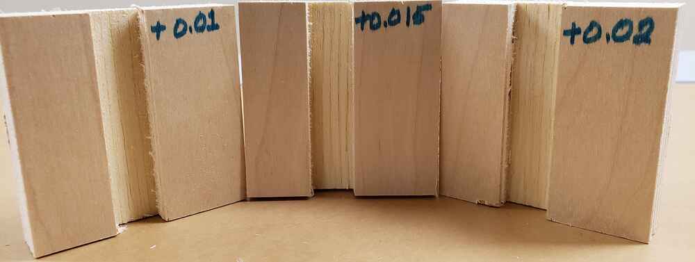
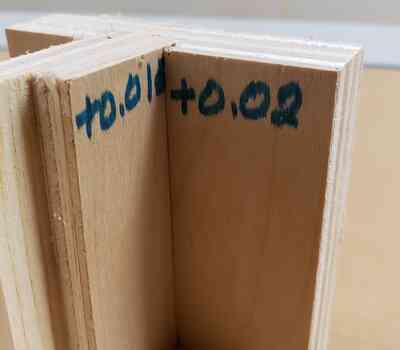
Oversizing the channel by 0.02" gives the best result. The other test channels proved to be too narrow to fit a piece in without considerable force.
Designing
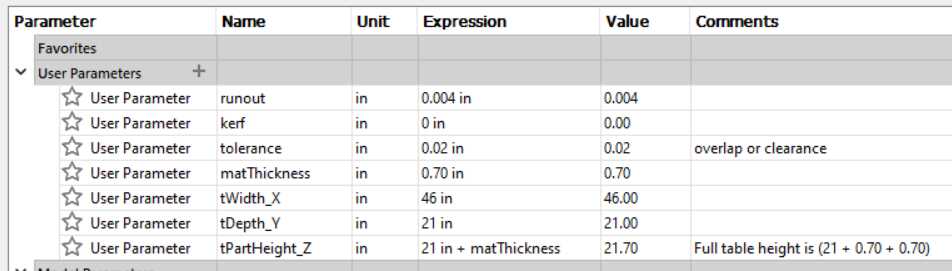
Now that I know the tolerance, kerf (needed for the laser cutter), and additionally the runout, I can add them to a list of parameters I'll use quite often in the design of this table. Below is a screenshot of my complete list.
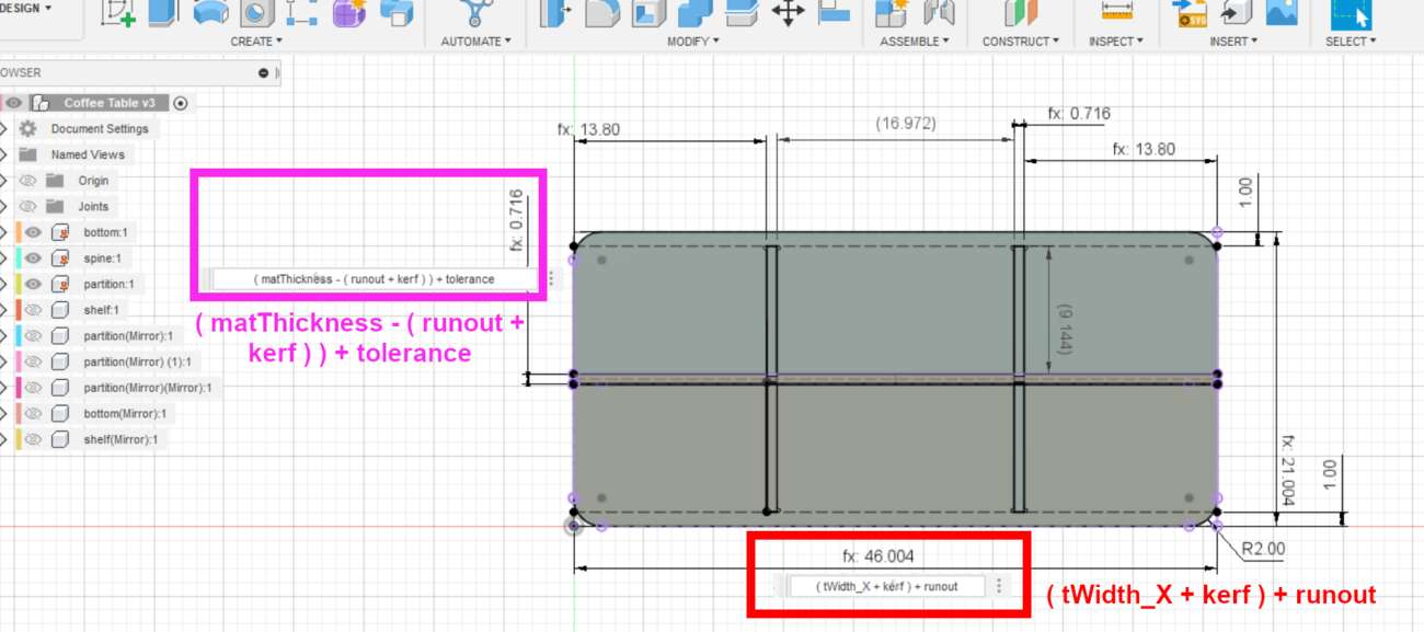
I took a bottom up approach and started with the bottom piece. The following image shows the dimensions of the piece and how runout and kerf was accounted for in the dimensioning.
The red square shows the table is 46" long total, but since the laser cutter cuts directly on the toolpath, this dimension would be slightly decreased by laser kerf. Additionally, the runout on the Shopbot would further decrease this dimension, so to account for both, I add both the kerf and runout to 46" on the front end to offset.
Below, the purple square shows the math used to account for the kerf and runout. In this instance, the base width of the channel is 0.70". The kerf and runout would increase the width of the channel during the fabrication process, so to offset and get the width back down to 0.70" (represented by parameter "matThickness" - material thickness), I subtract both kerf and runout from 0.70" on the front end. Lastly, I need to adjust this 0.70" channel for "tolerance". As already stated, adding another 0.02" to the 0.70" width of the channel gives me the clearance I need between the pieces for a good fit. In total, when fabricated, the channel width is 0.72".
This is the approach I took throughout the designing process, stopping to think about how my design will be affected by the characterization of the machines used and compensating for those factors. This table has 4 main pieces, 3 of which were mirrored to form the remain parts of the table.
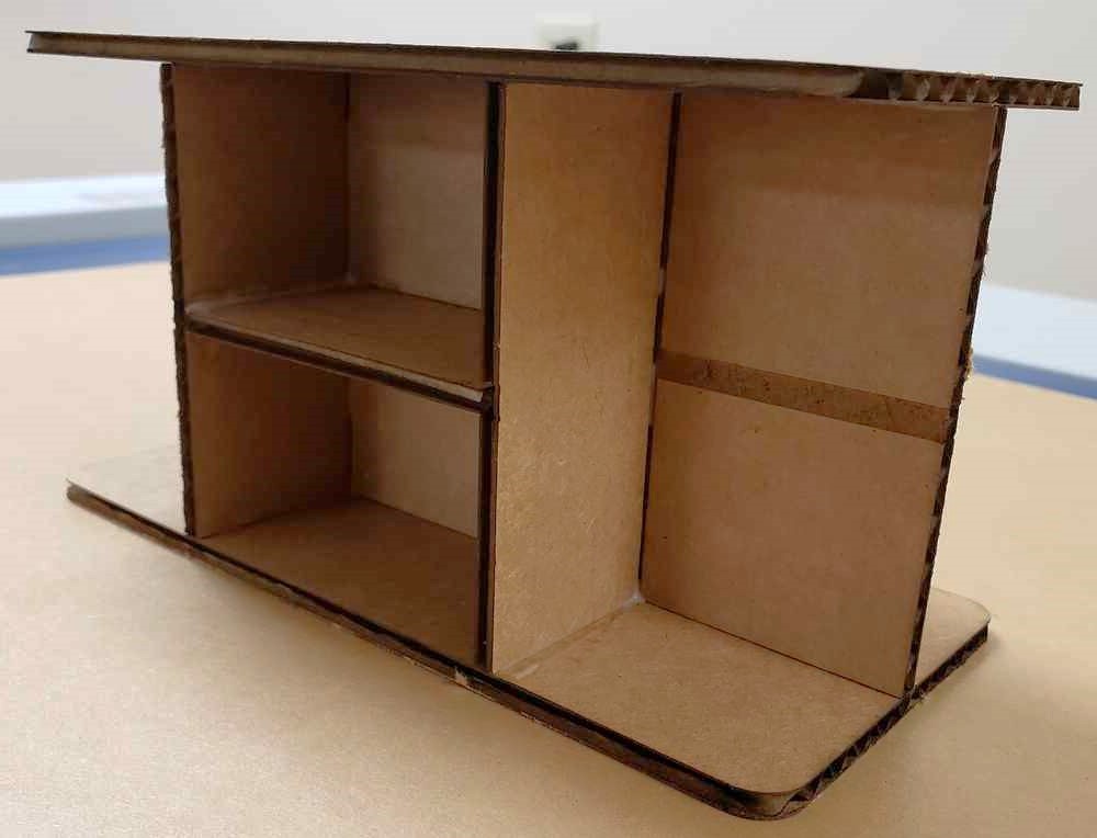
Scale model
A scale model can show potential problems with the design that was missed during the design process. There are some parameters I need to change to accomodate the fabraction of it on the laser cutter.
- kerf: 0.007"
- material thickness: 0.19"
The parameters below are zeroed out because they are either not applicable to the laser cutter or this particular model.
- runout: 0
- tolerance: 0
Even though I won't be utilizing joints in this scale model, I will etch them in which will help me align the pieces that need to be glued.
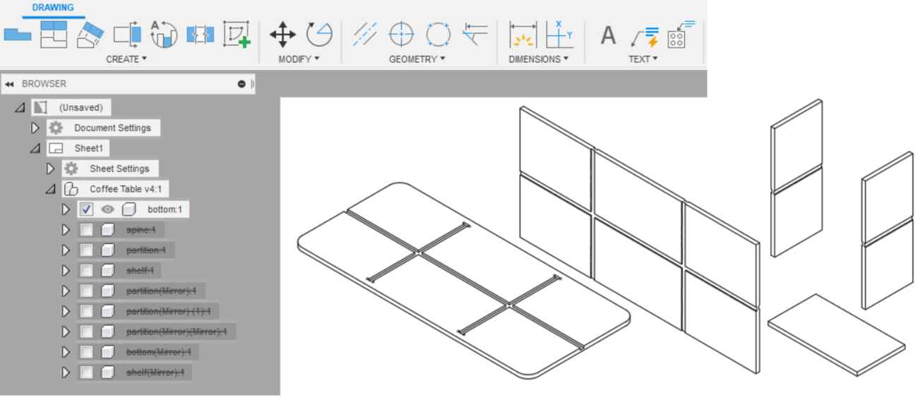
To be thorough, I want to also address another problem with a scale model in regards to material thickness. The thickness of the cardboard is 0.19". I intend to do a 1:6th scale model. This means that if I do not modify the material thickness, it will scale down to 1/6 of 0.19", that is 0.19/6 = 0.031, making the channels only a fraction of the thickness of the cardboard. In order to properly size the material thickness to 0.19in in a 1/6th model, I need to first multiply it by a factor of 6, that is, 0.19" x 6 = 1.14" and assign this to the parameter "matThickness" in the CAD model. Now when I export a 1:6 scale drawing, the channels will be properly sized at 0.19".
Though the image below shows several pieces in 2.5D, I exported each piece individually in the 2D format as a .dxf file.
Printing to the laser cutter
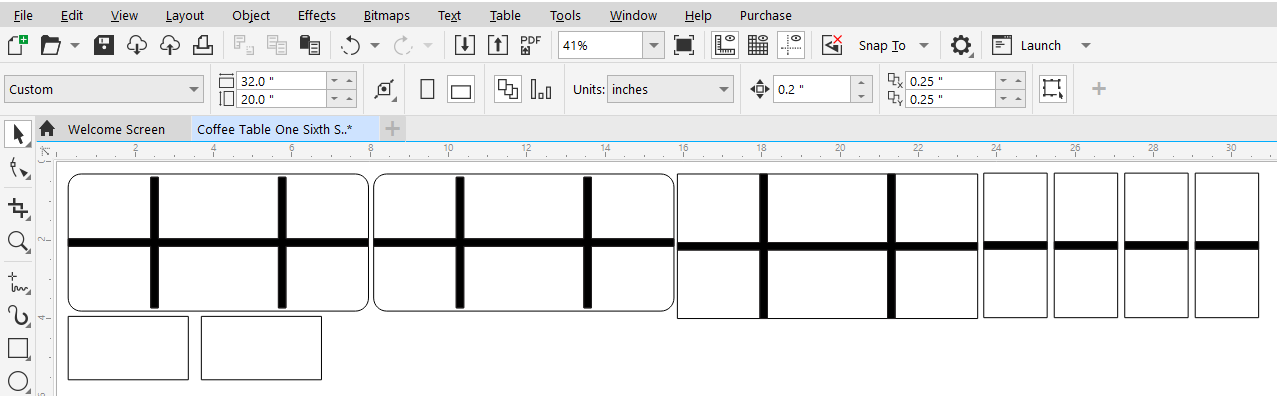
Each .dxf file was imported into Corel Draw (evaluation version) and layed out. I converted the lines that need to be cut to a "hairline" thickness and the joint channels were left as-is so they will be etched instead of cut. The etched lines will help me with placement and alignment when I go to glue the pieces together.
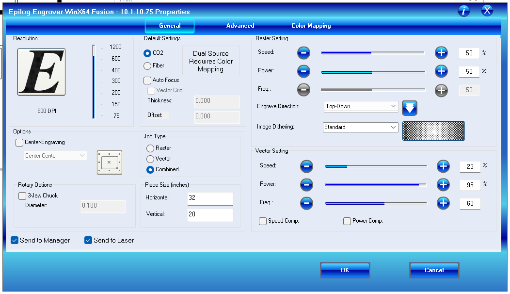
This is the dialog box that pops up when printing to the laser cutter. We have a CO2 laser, I have both vector and raster lines, the bed is 32"Lx20"W, the raster settings were left at default, and the vector settings are 23s, 95p, 60f. I uncheck speed comp and/or power comp if they are checked as those settings aren't relevant here.
I didn't do a perfect job of gluing the model together but everything checks out. Below is the resulting cardboard model.
Toolpathing for Shopbot
Software
- VCarve Pro - ShopBot Edition 9.5
As with the model, I exported the pieces again in the .dxf format, this time in a 1:1 scale using the CAD parameters appropriate for the Shopbot, and imported them into VCarve. Those parameters are:
- kerf: 0 (Shopbot accounts for kerf)
- runout: 0.004"
- tolerance: 0.02"
- material thickness: 0.70"
Using fixtures
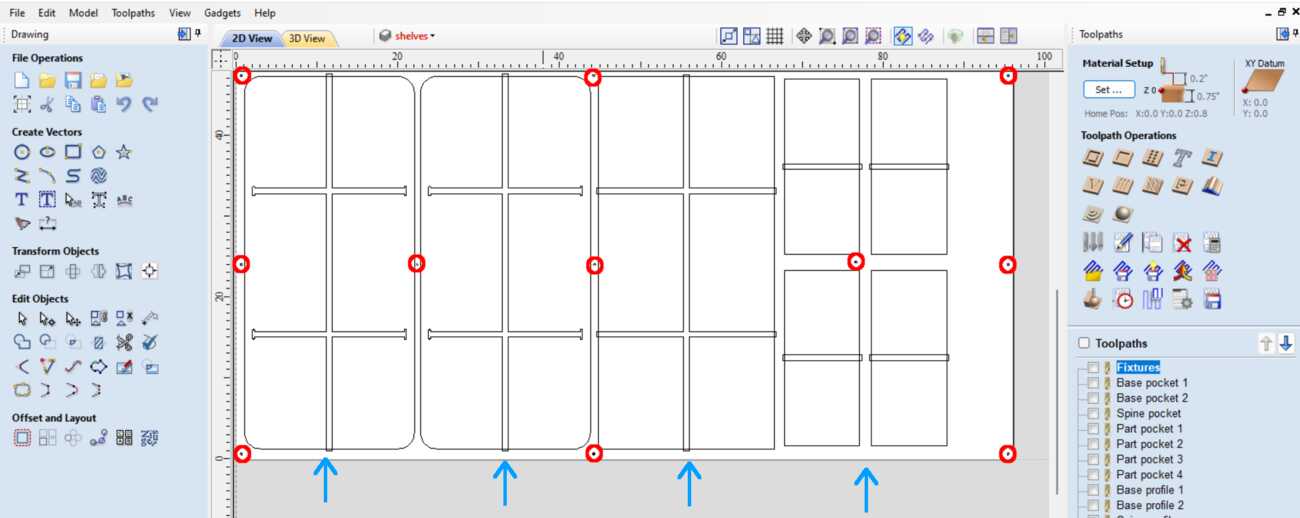
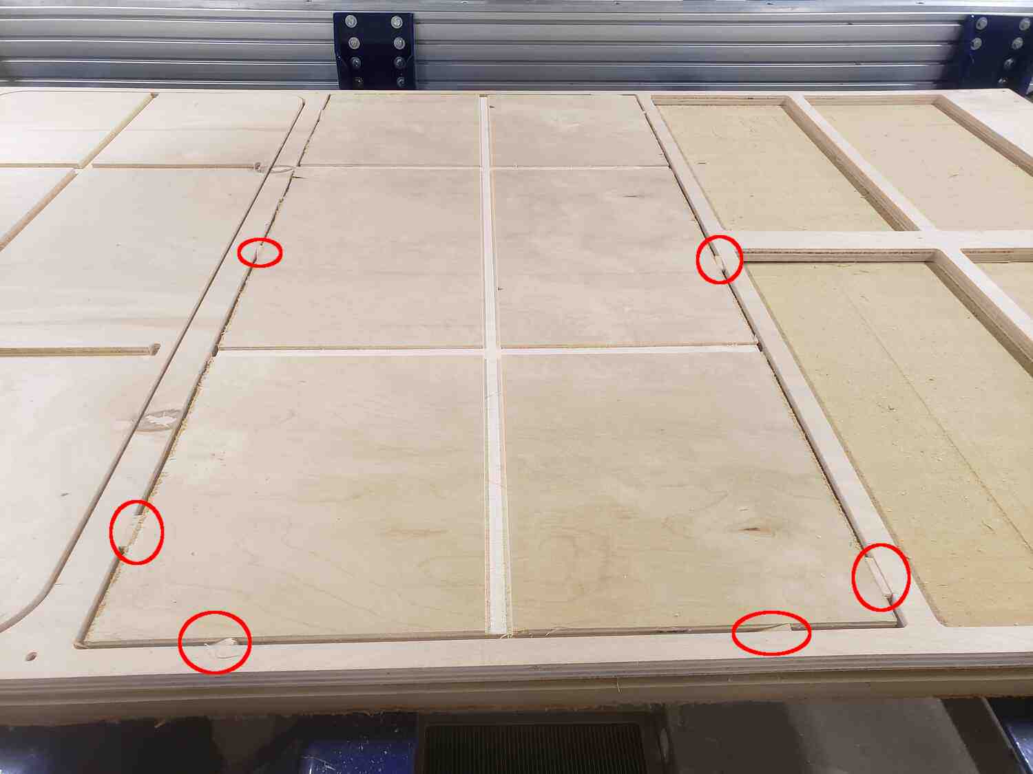
Below, the red circles indicate the placements for peck drilling my fixtures, which are screws in this case. The blue arrows point to the layout of pieces.
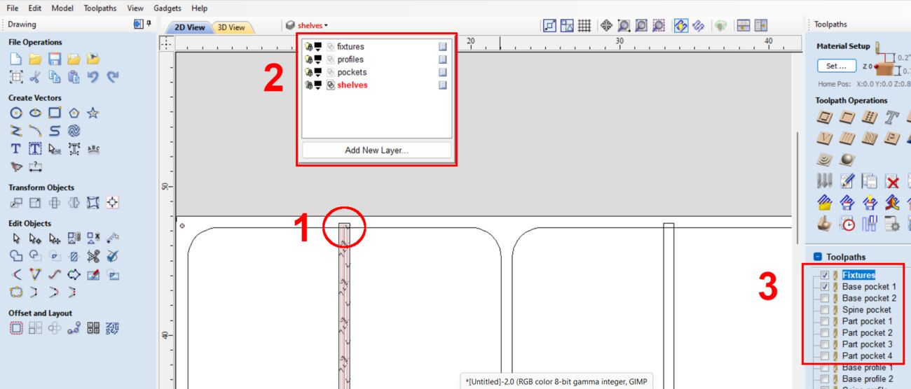
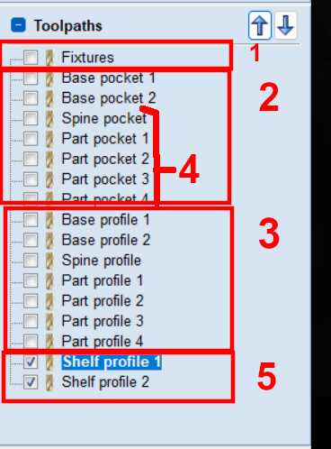
Not including the fixtures, I basically have 2 types of toolpaths, pockets and profiles. I have organized these toolpaths into layers (Ref. 2 in image below). It makes sense to do the pockets first (Ref. 3) and profiles afterwards. I needed to make sure that certain pockets extended to the very edge of the piece, so I extended the toolpath slightly beyond the boundary of the piece as in Ref. 1 in the image below.
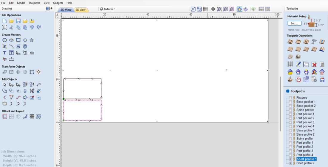
The current layout shows the first run which will completely exhaust the 4'x8' sheet of plywood, so the shelves, which were placed on a layer by themselves, will be a second run.
Adjusting feeds, speeds, depth of cut
Pockets:
- tool: 1/4" Down-cut (57-910)
- speeds: 12000 rpm
- feeds: 3.0 in/s
- cut depth: 0.35 in
- pass depth: 0.125 in (1/2 of tool diameter)
- passes: 3
Profiles:
- tool: 1/4" Down-cut (57-910)
- speeds: 14000 rpm
- feeds: 3.0 in/s
- cut depth: 0.75 in
- pass depth: 0.25 in (tool diameter)
- passes: 3
Here is an overview of the order of operations.
-
-
Air cut drill pecks
- Run drill pecks and apply fixtures
-
Air cut pockets
- Cut Pockets - first side
-
Air cut profiles
- Cut Profiles
-
Flip and fixture the double sided pieces in place
- Air cut pockets again, to be safe
- Cut Pockets - second side
-
Run final job
- Rerun the process for drill pecks and fixture new material to the table
- Run the process for air cutting the shelves followed by the actual profile cuts
-
Air cut drill pecks
-
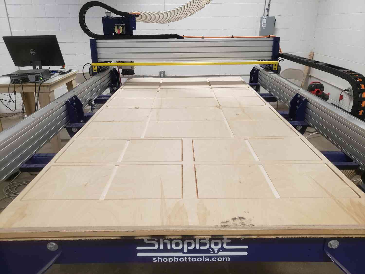
Setting up the machine
- Check the table for debris
- Check the gantry for movement
- Run X,Y limits
- Run spindle warmup routine
- Install collet and milling tool
- Set X,Y,Z origins
- Run the .sbp toolpaths file in the order specified earlier
Stages 1-3 have been completed. I've cut the pockets on the first side and profiles. The next stage is to flip the doubles sided pieces over for another pocket run. Of course I stopped to carefully vacuum up excess sawdust.
Kerf filler fixtures
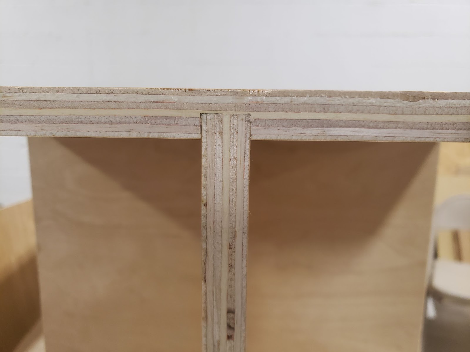
I wanted to affix the double sided pieces without using screws, so I decided on using strips of plywood or "kerf fillers" that were 1/4" in thickness. These were made previously made from plywood scraps. They filled the kerf and locked the double sided pieces in place as shown in the image below.
I paid particular attention to keeping the top surface, edges of the double sided piece level to surrounding area to hopefully minimize sloping and keep all of the pockets depths consistent to the first side.
Once all the pieces were cut, assembly was just a matter of slotting the pieces together. This table was assembled with no fixtures and is self supporting.