3D Printing & Scanning
- Printer: 3DWOX 2X
- Nozzle Width: 0.4mm
- Print Layer Width: 0.2mm
- Max. Print Length: W:210mm, D:200mm, H:195mm
- Printable materials: PLA, ABS(Sindoh)
- Open Materials: PLA, ABS, ASA, PETG
I chose one of several 3DWOX 2X printers to characterize. I used the default 3DWOX slicer software. Adding supports is simple and there is an auto bed leveling feature that evaluates the bed and tells you what to do to get the bed level.
Testing Design Rules
Supported:
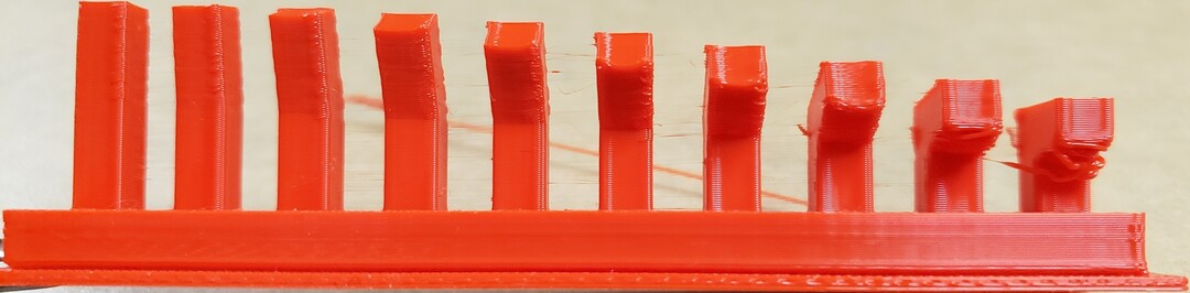
Overhang:
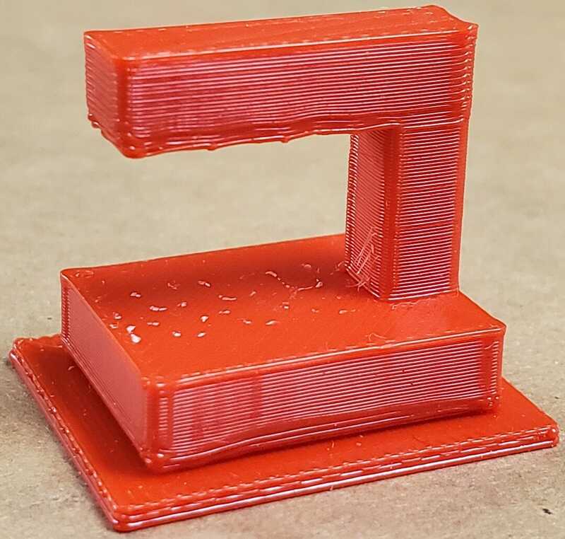
By default, the 3DWOX 2X use a zigzag supports unless otherwise stated. This overhang was printed with the default settings. Gravity is always at work on the print layers, so the print layers need
to keep from sagging or forming a rats nest underneath the form. It's pretty clear the first 5 or 6 layers on the support structure have a lasangna effect, suffering from sagging and pinching despite using supports.
Clearance
In this design rule test, the numbers are in thousandths of an inch or 0.3 mm. The smallest gap width this printer can print before fusion occurs is 0.003 in or 0.3 mm.
Unsupported:
Angle
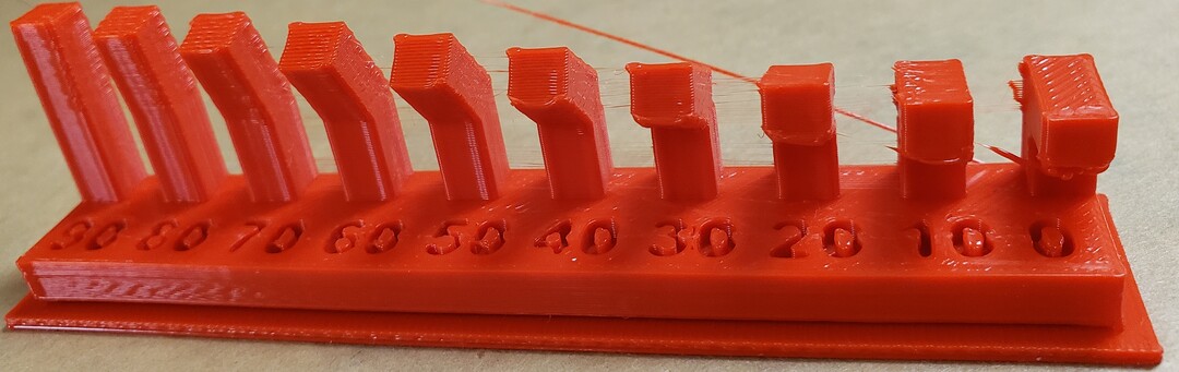
For angled prints, 30° is where I start to get tolerable results.
Overhang
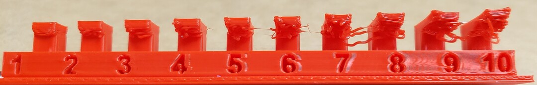
All of these unsupported overhangs resulted in the spaghetti.
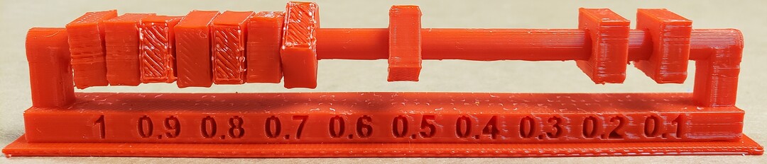
Bridging
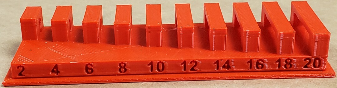
All of these bridged overhangs worked pretty well even though I could still see some slight sagging underneath the 20 mm bridge.
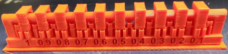
Wall Thickness
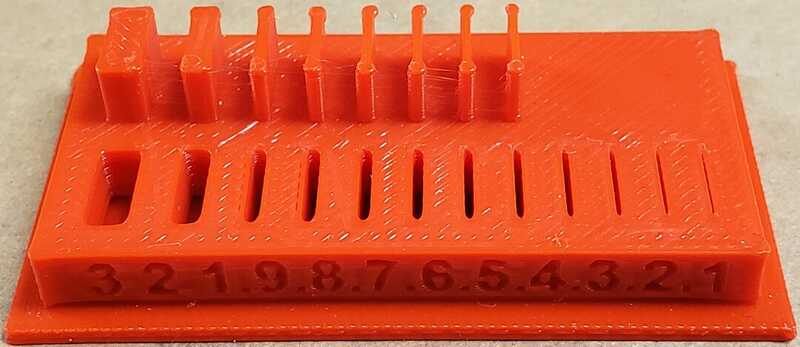 The thinest wall thickness this printer can acheive is 0.5 mm. Anything below 0.5 mm doesn't get printed, however
the printer can print a discernable gap down to 0.1 mm.
The thinest wall thickness this printer can acheive is 0.5 mm. Anything below 0.5 mm doesn't get printed, however
the printer can print a discernable gap down to 0.1 mm.
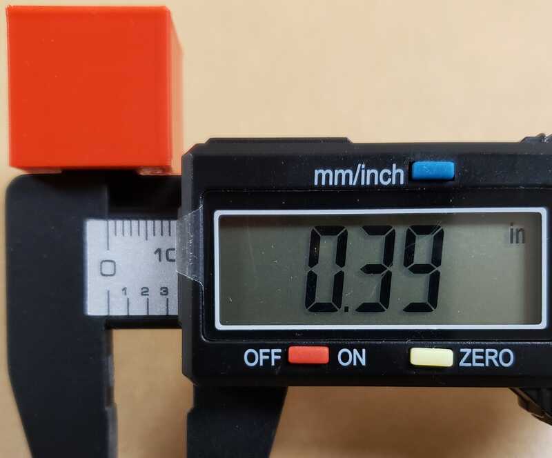
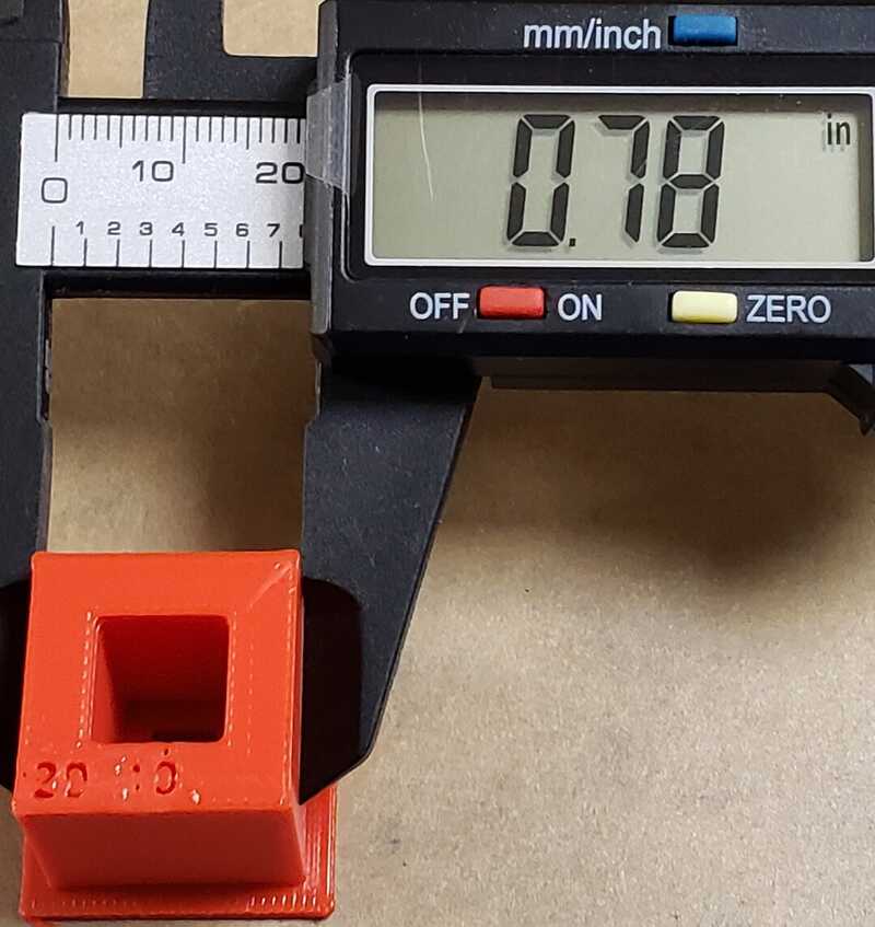
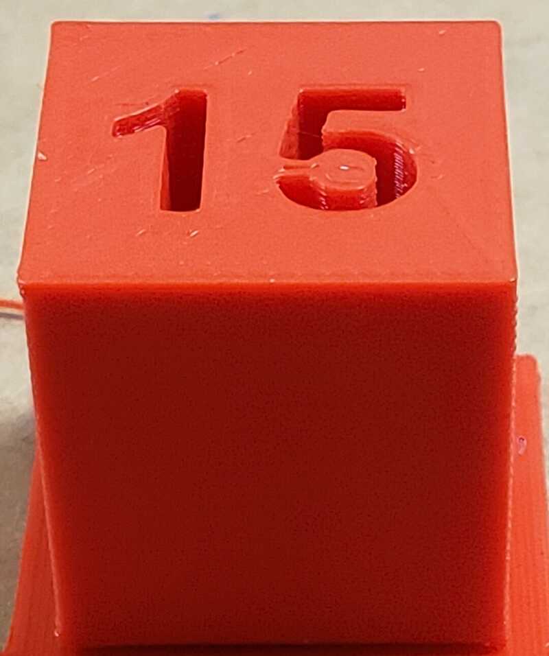
Dimension

The external dimensions of the print measured out to be 0.78 in2 (19.812 mm2), a difference of 0.188 mm. Internal dimensions are 0.39 in2 (9.906 mm2), a difference of 0.094 mm.
Anisotropy
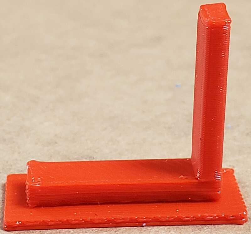
The bindings between the horizontal layers are the weakest point of the structure and would not hold up well to significant stress placed upon them.
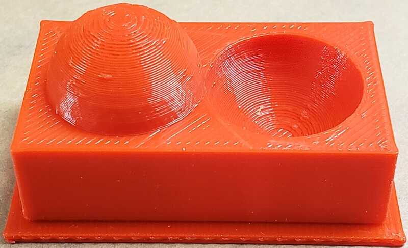
Surface Finish
Infill
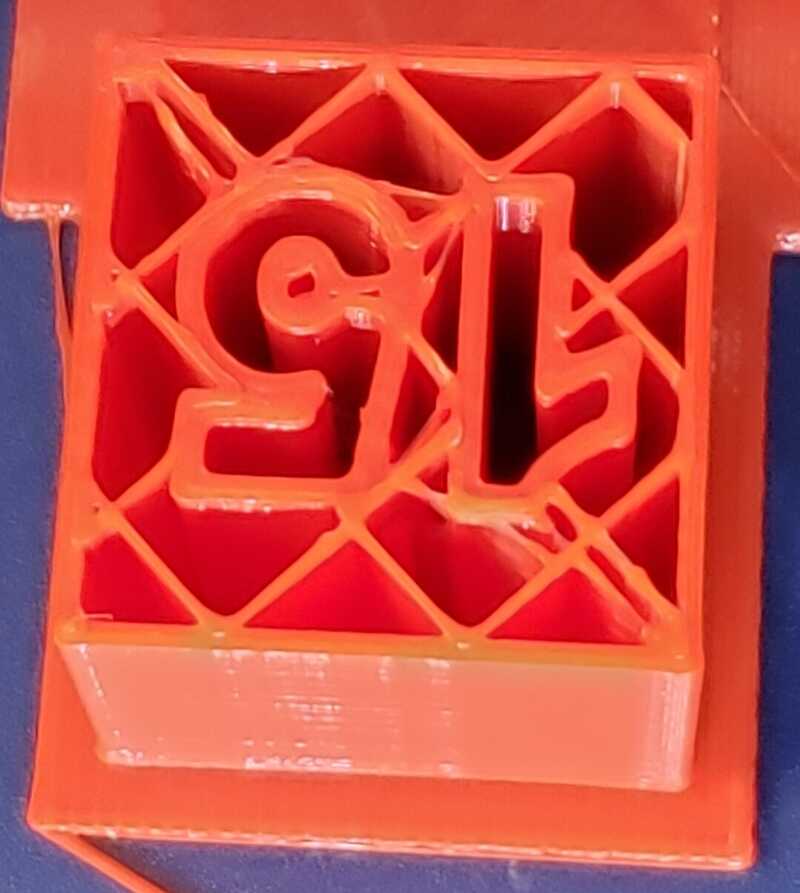
I printed 3 infill tests. Two were printed with a 15% infill, 1 with a line pattern and 1 with a grid pattern. The last was printed with a 100% infill with a grid pattern.
- 15% infills
- weighed in at 4g
- measurements
- 19.9 mm wide X axis
- 20.2 mm wide Y axis
- 20.0 mm high
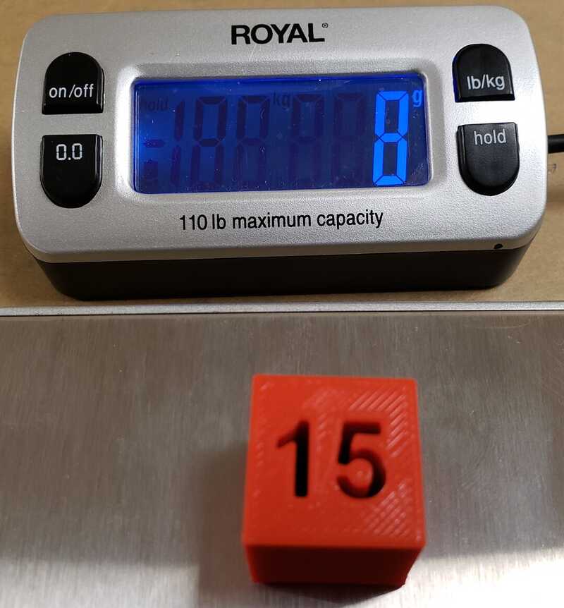
- 100% infill
- weighed in at 8g
- measurements
- 19.8 mm wide X axis
- 20.1 mm wide Z axis
- 20.0 mm high
Characterization
Overhangs
- 90° overhangs require supports.
Clearance
- A minimum clearance of 0.003 in is needed between bodies to keep them from
  fusing together when printed. (I later learned from examining the original FreeCad
  stl files that the 0.003 in clearance was based on the radius of the ring. If I need
  clearance around the full diameter of a part, I would need "0.003 in *2" or 0.006 in
  of clearance.)
Angles
- Printing overhangs at an angle of 30° or more is needed to prevent a stringy
  mess from forming underneath the overhang.
Wall Thickness
- The smallest wall thickness this printer can print is 0.5 mm. Anything below
  0.5 mm doesn't get printed.

- Discernable gap widths range from 3mm down to 0.1 mm.
Bridging
- Bridging works from 2mm up to 20 mm (19.6 mm in my case).
Dimensions
- The dimension of the overall print is 0.188 mm (or 0.0074 in) smaller than the
  intended dimension for all 3 axis and the wall thickness dimension is
  0.174 mm (or 0.19 in) smaller.
Anisotropy - What I learned here is to design the part with print orientation in mind such that stress would be spread across the layers rather than the layer bindings.
Scanning
- Method: Photogrammetry
- Software: Meshroom
- Subject: 3DTotal Resin Artist Anatomy Model
- Camera: Sony Cyber-shot DCS-RX100
- Photos Taken: 120
I set the model on a small table and I took a series of photos at eye level and a series of photos above and below eye level. I copied the photos to my laptop, loaded them in Meshroom and clicked start. Though my laptop has a graphics card, my laptop was struggling to process the files. It was taking hours to process and could stop and error out. This might be due to the fact it has only 8 gb of memory and I need to upgrade; so I moved the project to my desktop. It has an NVIDIA GeForce RTX 2070 with 32 gigs of memory. The graphics card appeared to have made really short work of the processing. I didn't babysit the processing but I believe it was done within an hour.
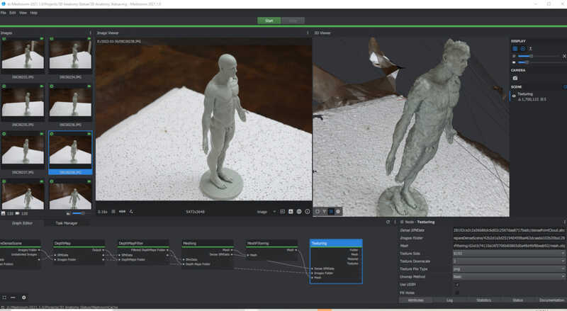
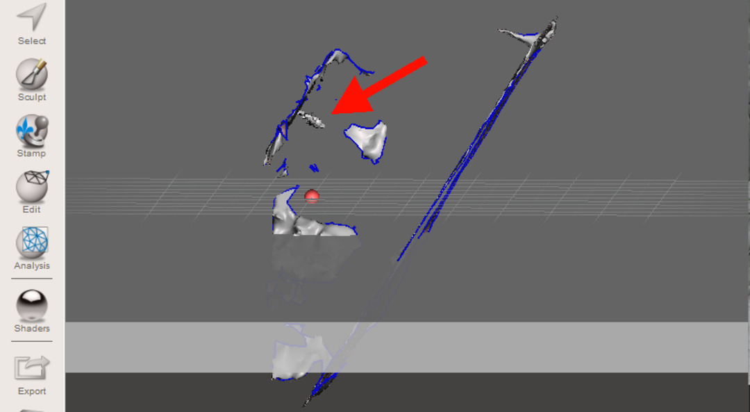
What you see in the image above is Meshroom having a hard time distinguishing the right side of the model from the background, I believe. I've gone through this 3 times with this same model, with 3 different sets of photos and 2 different locations. I've concluded that due to the neutral color of the resin, Meshroom has a harder time making distictions between it and the background; especially on the smooth side of the model, that is, the right side. Each time, the right side is rendered with a bumpy surface and the lower right leg is missing.
Take-aways on the scanning process:
- With this model, I should have taken the photos against a dark background
- Coating the resin model with a little powder might have helped by cutting back on light reflection which could confused the algorithm
- Placing the model on a turntable versus walking around a table might have been a better option
- I will not get a perfect result with this method
Fixing the model
I took the .obj file created by Meshroom and imported it into Meshmixer. Meshmixer is very versitile and one can get lost in all the features, so I took a straight forward approach to fixing my model. Below is an outline of my approach to preparing my model for printing.
- Import the digitally reconstructed object
- Discard the unwanted portions that Meshroom captured (background / environment)
- Split the 3D anatomy object in half, delete the bumpy side (right), keep the left
- Duplicate the left side and mirror it, thus recreating the right side
- Merge the original object and the mirrored object together
- Fix the holes in the model
- Convert it to a solid
- Export .stl file
Discarding the unwanted portions
I imported the object into Meshmixer. The first thing I want to do is get rid of the unwanted stuff. The red arrow (Photo A below) points to the actual anatomy model. This is what I want to keep. It's relatively small compared to the reconstructed background surrounding it.
Photo A
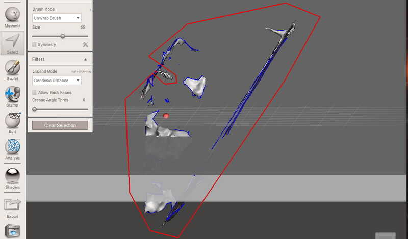
To get rid of the background rubbish, I used the "Select" tool (Photo B below) to select the unwanted portions, then clicked "Edit" > "Discard". I repeat that process until only the anatomy model is left.
Photo B
Splitting the model
Using the "Plane Cut", I split the object down the middle and kept the better half.
Duplicate, Mirror and Merge
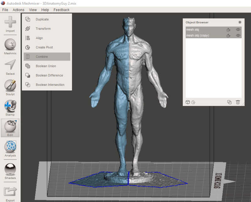
Using the object browser in Meshmixer, I duplicated the left side object, mirrored it, then combined the 2 objects.
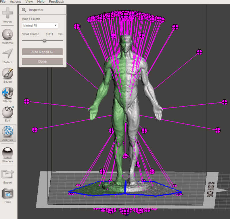
Repairing the defects
Using Meshmixer's "Analysis > Inspector" to auto-repair the defects in the mesh.
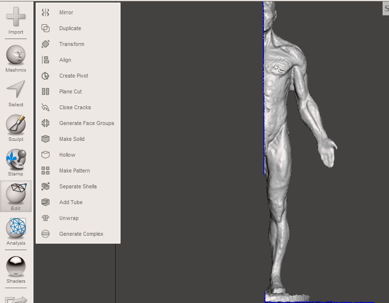
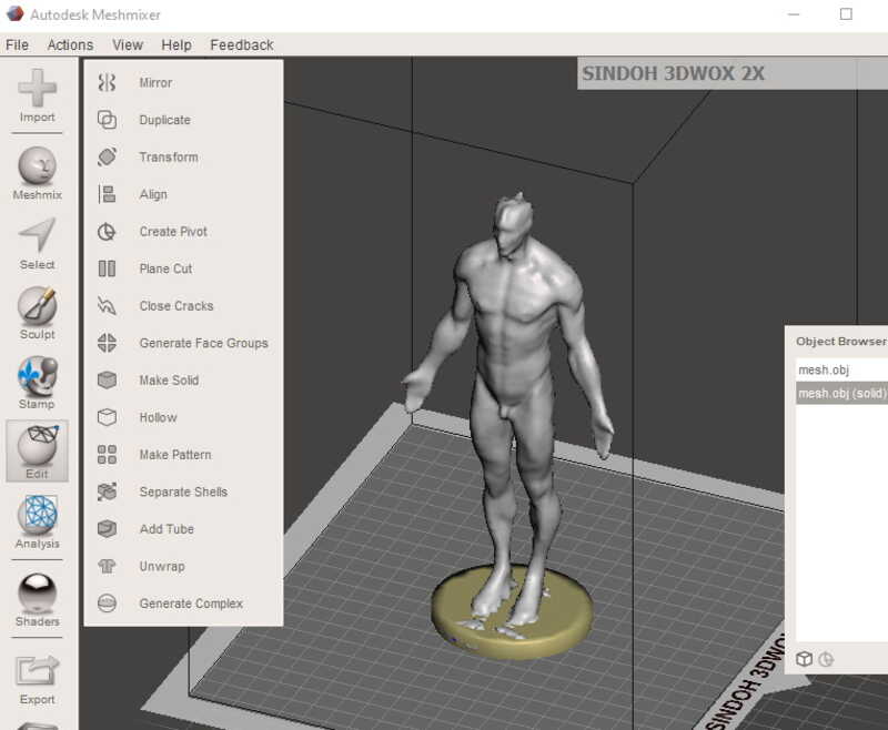
Converting to a solid
Under the "Edit" menu, I converted the mesh to a solid using "Make Solid". I recreated the base the model is standing on using the Meshmix cylinder primitive. I sliced a small layer of the cylinder and merged it to the bottom of the model's feet. Meshmixer had problems reconstructing the head, and as a result, it's not fully formed, thus it looks like the crown of The Knight King from GOT.
3D Printing Project
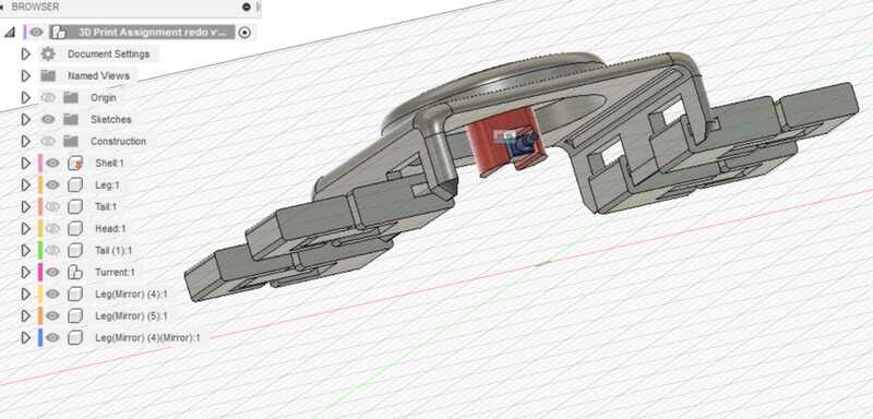
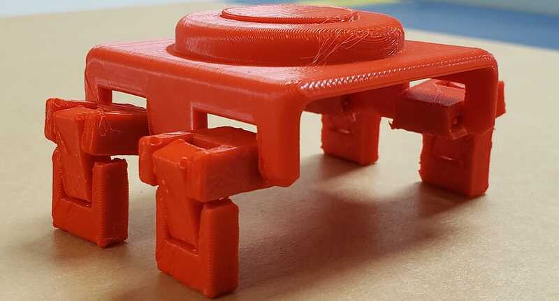
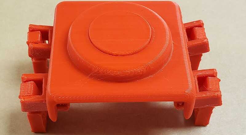
Using the design charateristics established by the tests, I wanted to create something with some visual interest and purpose, so I created this toy. The legs are the piece that would be hard to create subtractively because they have hidden geometry in the legs the make the joints work.
With the first couple of prints, I had some problems with legs fusing together, so I went back to examine the FreeCad file for the "clearance" test. In the design rules test, I established that a clearance of at least 0.003 inch was needed to prevent fusing. I followed that rule so the fusing wasn't making sense. After giving it some thought, I realized that the original FreeCad files were available for download, so I examined the "clearance.stl" file. I noticed that the clearace was based on the radius of the ring, not the diameter. That means the total clearance needed, based on the diameter, would be 2 times 0.003 or 0.006 in. I updated my clearance parameter and that resolved the fusing.
A view of the toy design
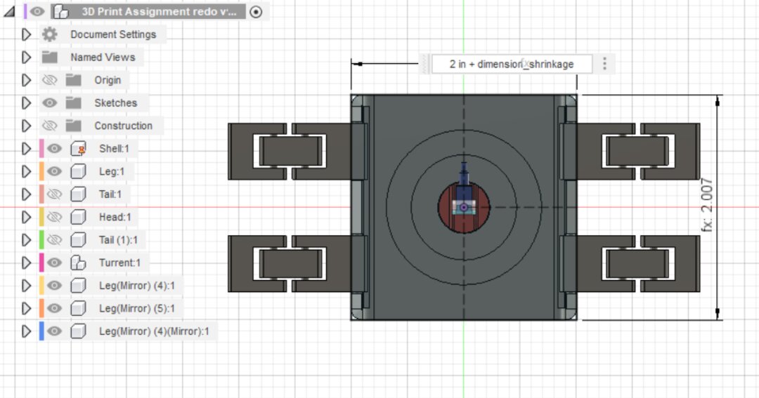
Compensating for shrinkage of length and width due to cooling.
Compensating for thickness shrinkage
- Using a shell command to hollow out cube and adding my shrinkage parameter
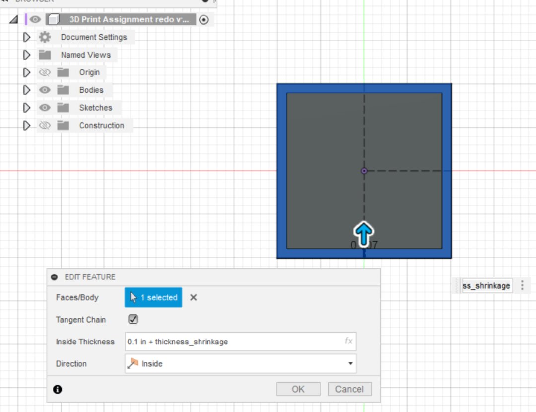
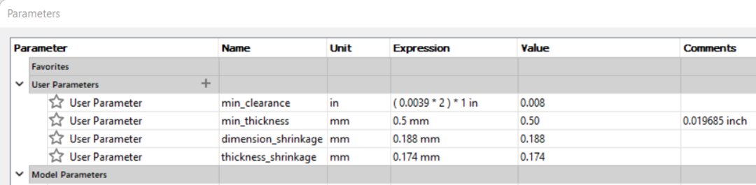
Parameters list
Slicing
Slicer: 3DWOX Desktop x64
Default print settings:
- Filament Used: PLA
- Layer Height: 0.15 mm
- Bed Adhesion: Raft
- Infill Density: 15%
- Infill Pattern: Grid
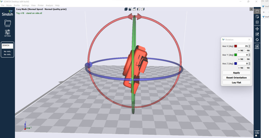
I used 3DWOX default slicing software to orientate the model and add supports. In the photo above, I work out that this configuration would give me the cleanest print in terms of minimizing support attachments affecting the finish.
The Prints - The Toy

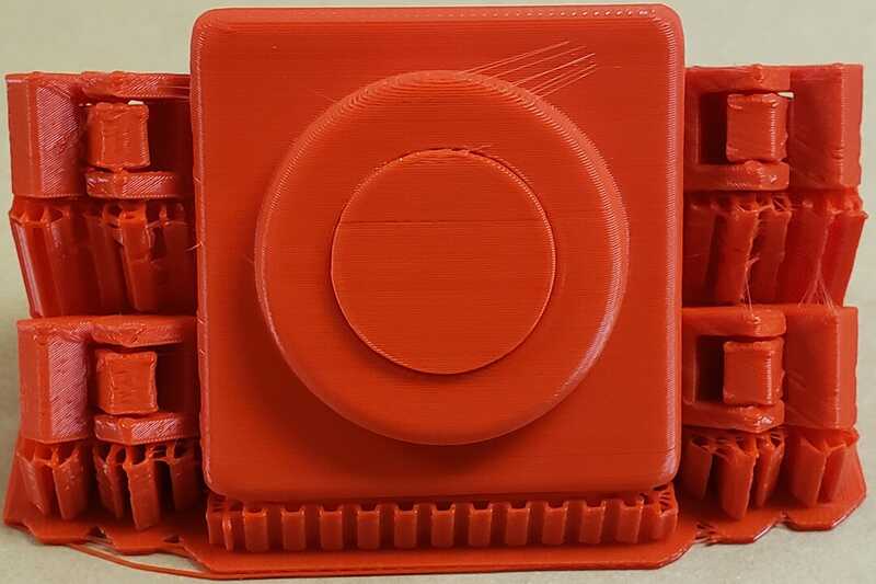
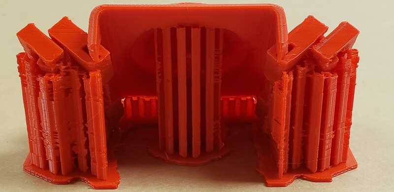

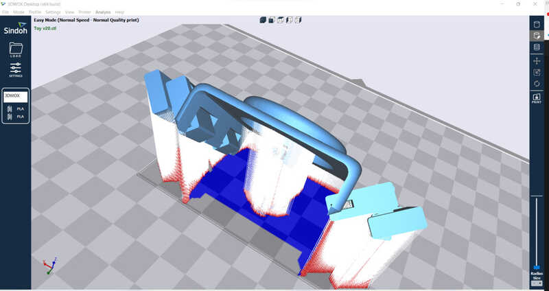
I went through a few prints of The Toy, each time working out how I can get a print with fewer support artifacts left behind. I tried printing in different orientations, right side up, up side down and each time, the artifacts left behind by the supports had a significant affect on the finish wherever they touched. I then made a print with the legs angled to reduce the supports needed there. That helped. Then I realized that if I angled the legs and also angled the entire body of the toy, the supports might hit areas where the artifacts would be less noticable and have less of an affect. The final orientation was printing the body at 50 degrees with the legs angled. The take-away for me here is that orientation can take place on more than one plane and that could help produce a better print.
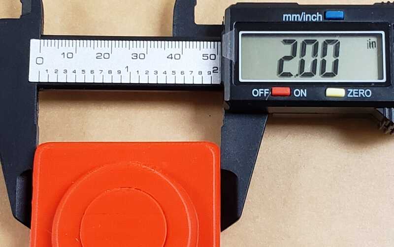
Measurements
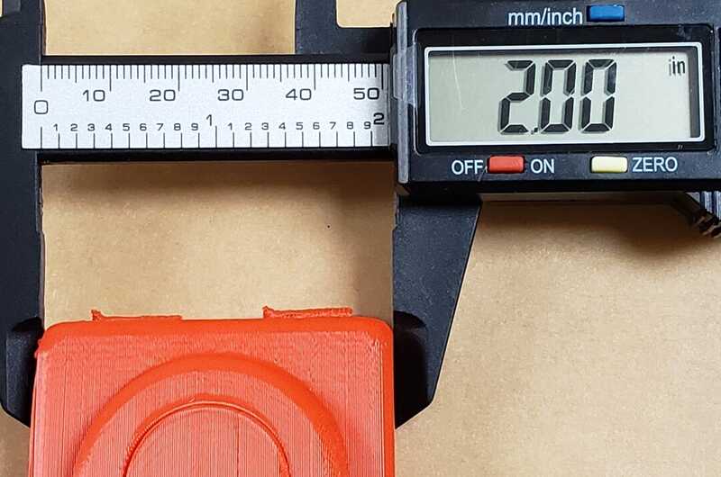
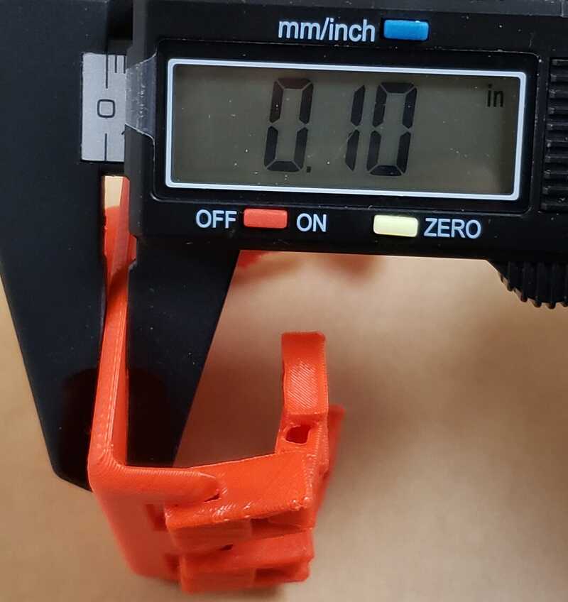
The design was dimensioned at "2 in x 2 in" with a thickness of 0.10 in and the printed piece is "2 in x 2 in" by 0.10 in thickness.
Width
Length
Thickness
Learning outcomes
Identify the advantages and limitations of 3D printing
-
Advantages
- Provides a means to create geometry that is not possible with the subtractive method
- The technology is widely available and relatively cheap
- One can get started with basic knowledge
-
Limits:
- Control over accuracy and precision
- The anisotropic nature of 3D printing - the printed object won't hold up well to forces acting against the layer bindings therefore are weaker in that way compared to forces spread across multiple layers of the object out across multiple layers. Depending on the object being printed, one would may need to design around this.
- Production capacity is limited by time it takes to print
- Types of extruding materials that can be used
- Ultra fine particles, and volatiles can be emitted by the process and thus requires a safe work area, adequate ventilation and protective gear. This might prove prohibitive for some.
- Control over the surface texture/finish - may require post finishing
- Takes advanced knoweledge of the printer and the process to get more refined results
- Print size is limited by the area the gantry can cover
- Even among the same brand and model, printers may have different tolerances and performances
This couldn't be made subtractively because this toy has interlinking joints in the legs. It wouln't be possible for a tool to get into those small spaces.
Downloads: