Week13. Networking and Communications
| Assignment | |
|---|---|
| group | send a message between two projects link |
| individual | design, build, and connect wired or wireless node(s) with network or bus addresses |
Photo of the week
Take aways from the group Assignment
- the easiest communication between two projects wirelessly is possible when the projects use the same microprocessor
- we revied how to make communication through wifi for ESP32C3 here, its possible to make 2 ESP32C3 in seperate wifi networks through VPN
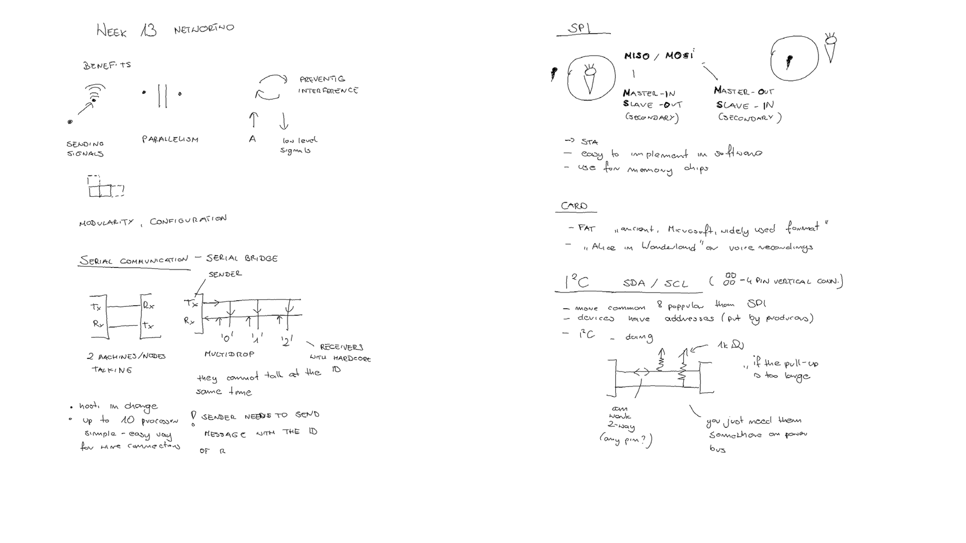
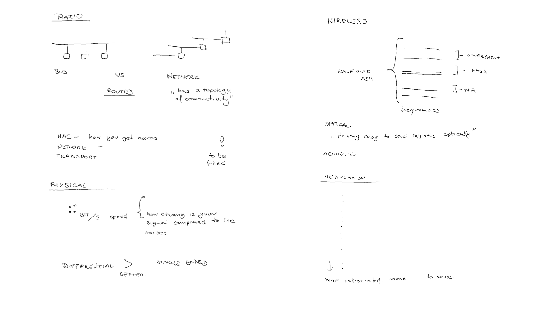
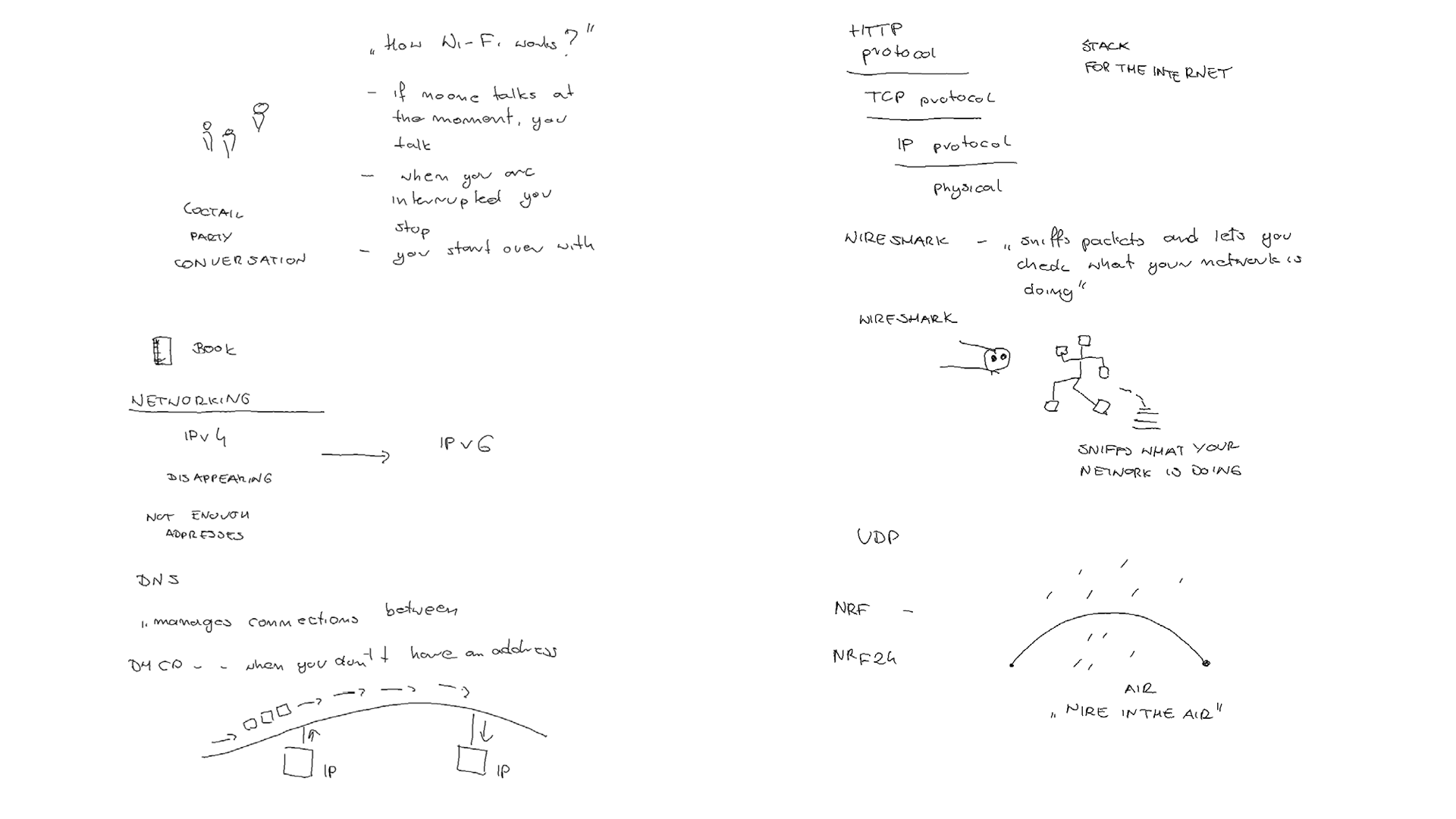
Lecture Notes
PCB Design & Production
I wanted to build a node that can connect though BLE and can be supported by battery. Below 2 designs with hole for the battery cables and development board with sockets for the XIAO_ESP32C3 or XIAO nRF52840 (Sense).
KiCad Design
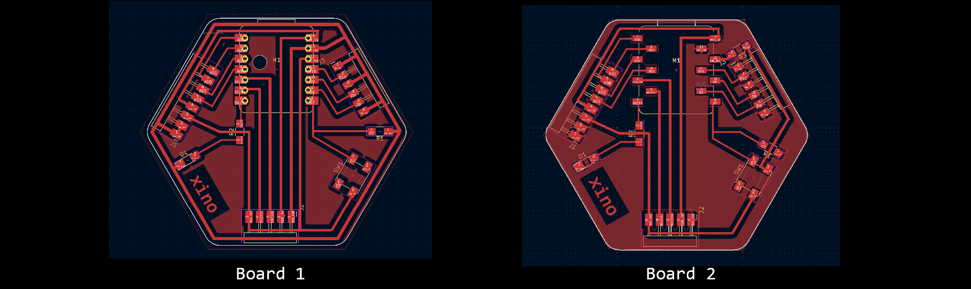 Fig. Xino-remote prototypes: left: with ground, right: without ground (final board that can work remotely) more here: xino-remote link.
To make a board where the plane is the GDN I followed the tutorial:
- Go to FCu Layer
- Select Add a Filled Zone (right panel, blue zone button)
- Click on canvas and the window will pop up: select FCu BCu and PWR_GDN.
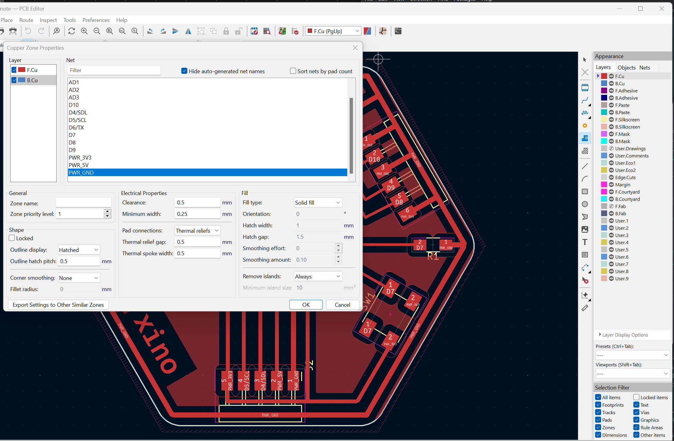
- Select the zone and wait. The zone will appear, the GDN wire will lose the clearance and GDN pads will get a cross. Your GDN plane is ready -> Make sure it connects all the GDN pads (otherwise with the rule check you will get the error).
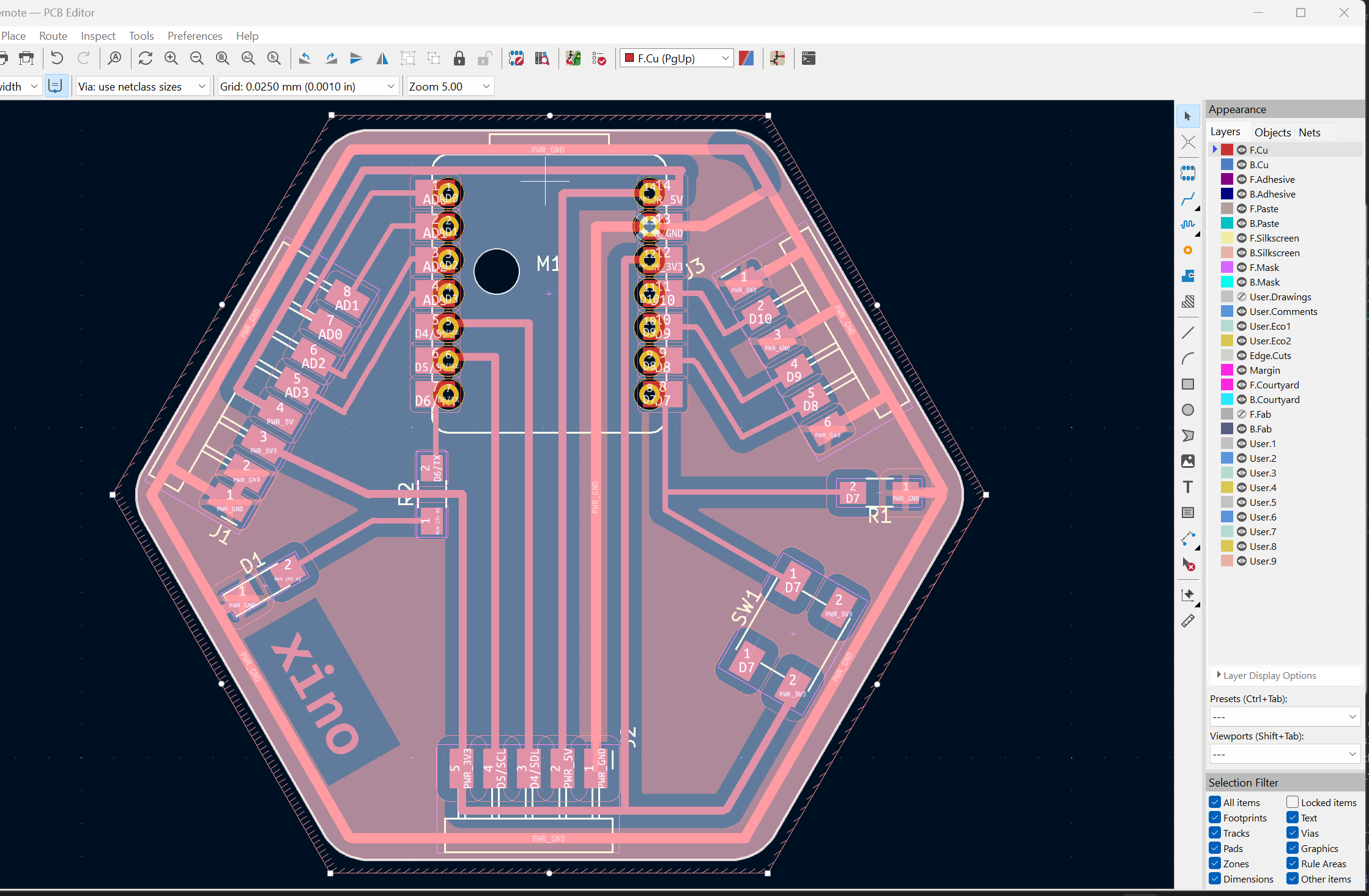
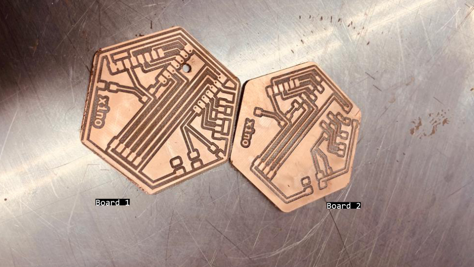 Fig. Xino-remote pcb prototypes fabricated: left: with ground, right: without ground.
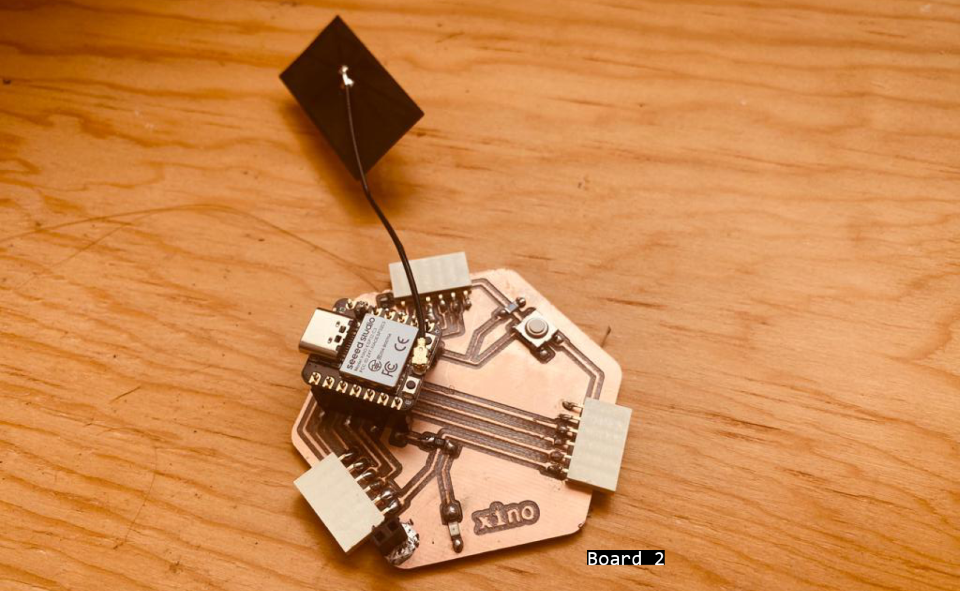 Fig. Xino-remote pcb prototype 1 soldered.
After soldering and connecting the board to the computer - pcb was working but after connecting it to the slots in the board it was stopping to work. After checkup with multimeter, I noticed that there was a continutity between GDN and 5V.
!!! 5V connected to the ground!!!!
I couldn’t find where the soldering could actually cause the problem. After taking the board out and closer inspection I noticed that:
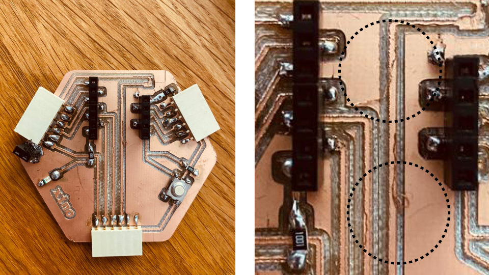 Fig. Xino-remote pcb prototype 1 soldered - the production left overs caused the short!.
XIAO_ESP32C3
ESP32-C3 adds support for the Bluetooth 5 (LE) protocol, with coded PHY and extended advertisement features, while it also provides data redundancy to the packets, thus improving the range (typically 100 meters). Furthermore, it supports the Bluetooth LE.
Board Check
/*
  Blink

// the setup function runs once when you press reset or power the board
void setup() {
  // initialize digital pin LED_BUILTIN as an output.
  pinMode(21, OUTPUT);
}

// the loop function runs over and over again forever
void loop() {
  digitalWrite(21, HIGH);  // turn the LED on (HIGH is the voltage level)
  delay(1000);                      // wait for a second
  digitalWrite(21, LOW);   // turn the LED off by making the voltage LOW
  delay(1000);                      // wait for a second
}
WIFI
I followed this tutorial to establish the WiFi network with ESP32C3.
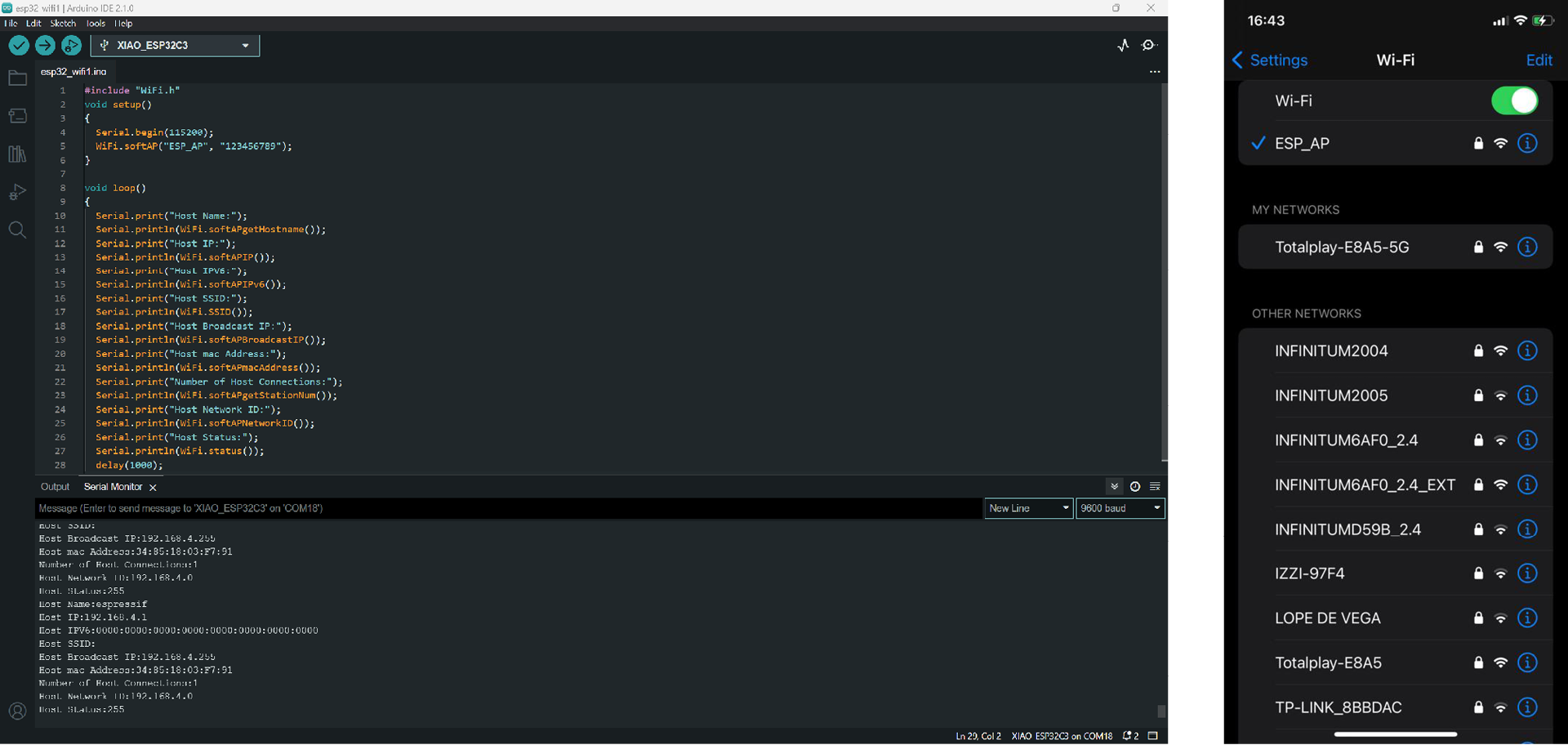 Fig. Xino-remote with ESP32C3 crating a WiFi network.
nRF52840 BLE Sense
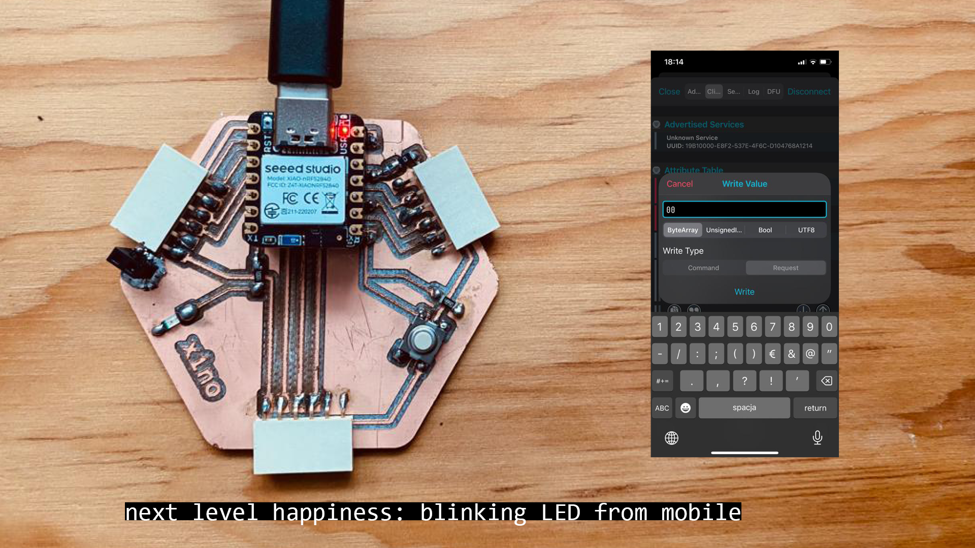
Turning on LED from mobile application
https://how2electronics.com/send-receive-data-to-mobile-app-with-xiao-ble-nrf52840-sense/
- Install Application
- Download a library called Arduino BLE. [Github library Arduino BLE] (https://github.com/arduino-libraries/ArduinoBLE).From this GitHub repository - Code-> download ZIP
- Add the Arduino BLE library to the Arduino Library folder using add zip option: Sketch->Include Library->Add .ZIP library -> select the downloaded .zip file “ArduinoBLE-master.zip”
- now upload the following:
#include <ArduinoBLE.h>

BLEService ledService("19B10000-E8F2-537E-4F6C-D104768A1214"); // Bluetooth® Low Energy LED Service

// Bluetooth® Low Energy LED Switch Characteristic - custom 128-bit UUID, read and writable by central
BLEByteCharacteristic switchCharacteristic("19B10001-E8F2-537E-4F6C-D104768A1214", BLERead | BLEWrite);

const int ledPin = LED_BUILTIN; // pin to use for the LED

void setup() {
  Serial.begin(9600);
  while (!Serial);

  // set LED pin to output mode
  pinMode(ledPin, OUTPUT);

  // begin initialization
  if (!BLE.begin()) {
    Serial.println("starting Bluetooth® Low Energy module failed!");

    while (1);
  }

  // set advertised local name and service UUID:
  BLE.setLocalName("LED");
  BLE.setAdvertisedService(ledService);

  // add the characteristic to the service
  ledService.addCharacteristic(switchCharacteristic);

  // add service
  BLE.addService(ledService);

  // set the initial value for the characeristic:
  switchCharacteristic.writeValue(0);

  // start advertising
  BLE.advertise();

  Serial.println("BLE LED Peripheral");
}

void loop() {
  // listen for Bluetooth® Low Energy peripherals to connect:
  BLEDevice central = BLE.central();

  // if a central is connected to peripheral:
  if (central) {
    Serial.print("Connected to central: ");
    // print the central's MAC address:
    Serial.println(central.address());

    // while the central is still connected to peripheral:
  while (central.connected()) {
        if (switchCharacteristic.written()) {
          if (switchCharacteristic.value()) {
            Serial.println("LED on");
            digitalWrite(ledPin, LOW); // changed from HIGH to LOW
          } else {
            Serial.println(F("LED off"));
            digitalWrite(ledPin, HIGH); // changed from LOW to HIGH
          }
        }
      }

    // when the central disconnects, print it out:
    Serial.print(F("Disconnected from central: "));
    Serial.println(central.address());
  }
}
- open nrf COnnect App -> connect to LED - > write ‘00’ or ‘01’
Some other helpful tutorials - https://www.youtube.com/watch?v=GsseX2rEjfw - https://randomnerdtutorials.com/esp32-bluetooth-low-energy-ble-arduino-ide/ - https://www.seeedstudio.com/blog/2022/06/14/top-10-real-world-machine-learning-projects-for-beginners-to-try-in-2022/
Two XIAO nRF52840 control LED via BLE
XIAO REMOTE (SLAVE)
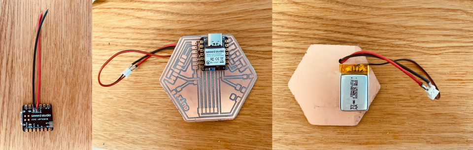 Fig. Xino-remote with nRF5240 and recharchable battery.
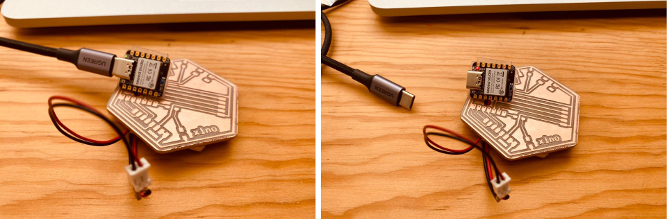 Fig. Xino-remote with nRF5240 and recharchable battery. Left- connected to computer -> the green charging diode lit up. Right: after uploading the file to turn on the inbuilt LED and disconnecting from USB-C, the XINO Remote works.
To connect two XIAO nRF52840 I followed this tutorial.
- Install library u8g2 -> Tools -> Manage Libraries -> U8g2
- For the board that is SLAVE(receiver that doesnt need any connection):
#include <ArduinoBLE.h>

BLEService ledService("19B10000-E8F2-537E-4F6C-D104768A1214"); // Bluetooth® Low Energy LED Service

// Bluetooth® Low Energy LED Switch Characteristic - custom 128-bit UUID, read and writable by central
BLEByteCharacteristic switchCharacteristic("19B10001-E8F2-537E-4F6C-D104768A1214", BLERead | BLEWrite);

const int ledPin = LED_BUILTIN; // pin to use for the LED -

void setup() {
  Serial.begin(9600);
  while (!Serial);

  // set LED pin to output mode
  pinMode(ledPin, OUTPUT);

  // begin initialization
  if (!BLE.begin()) {
    Serial.println("starting Bluetooth® Low Energy module failed!");

    while (1);
  }

  // set advertised local name and service UUID:
  BLE.setLocalName("XIAO");
  BLE.setAdvertisedService(ledService);

  // add the characteristic to the service
  ledService.addCharacteristic(switchCharacteristic);

  // add service
  BLE.addService(ledService);

  // set the initial value for the characeristic:
  switchCharacteristic.writeValue(0);

  // start advertising
  BLE.advertise();

  // print address
  Serial.print("Address: ");
  Serial.println(BLE.address());

  Serial.println("XIAO nRF52840 Peripheral");
}

void loop() {
  // listen for Bluetooth® Low Energy peripherals to connect:
  BLEDevice central = BLE.central();

  // if a central is connected to peripheral:
  if (central) {
    Serial.print("Connected to central: ");
    // print the central's MAC address:
    Serial.println(central.address());

    // while the central is still connected to peripheral:
    while (central.connected()) {
      // if the remote device wrote to the characteristic,
      // use the value to control the LED:
      if (switchCharacteristic.written()) {
        if (switchCharacteristic.value()) {   // any value other than 0
          Serial.println("LED on");
          digitalWrite(ledPin, HIGH);         // will turn the LED on
        } else {                              // a 0 value
          Serial.println(F("LED off"));
          digitalWrite(ledPin, LOW);          // will turn the LED off
        }
      }
    }

    // when the central disconnects, print it out:
    Serial.print(F("Disconnected from central: "));
    Serial.println(central.address());
  }
}
- For the board that is HOST (connected to computer):
#include <ArduinoBLE.h>
#include <U8x8lib.h>
#include <Wire.h>

// variables for button
const int buttonPin = D7;  # here put the pin number with your button
int oldButtonState = LOW;

void setup() {
  Serial.begin(9600);
  while (!Serial);

  // configure the button pin as input
  pinMode(buttonPin, INPUT_PULLUP);

  // initialize the Bluetooth® Low Energy hardware
  BLE.begin();

  Serial.println("Bluetooth® Low Energy Central - LED control");

  // start scanning for peripherals
  BLE.scanForName("XIAO");
}

void loop() {
  // check if a peripheral has been discovered
  BLEDevice peripheral = BLE.available();
  if (peripheral) {
    // discovered a peripheral, print out address, local name, and advertised service
    Serial.print("Found ");
    Serial.print(peripheral.address());
    Serial.print(" '");
    Serial.print(peripheral.localName());
    Serial.print("' ");
    Serial.print(peripheral.advertisedServiceUuid());
    Serial.println();

    if (peripheral.localName() != "XIAO") {
      return;
    }

    // stop scanning
    BLE.stopScan();

    system_control(peripheral);

    // peripheral disconnected, start scanning again
    BLE.scanForName("XIAO");
  }
  delay(100);
}

void system_control(BLEDevice peripheral) {
  // connect to the peripheral
  Serial.println("Connecting ...");

  if (peripheral.connect()) {
    Serial.println("Connected");
  } else {
    Serial.println("Failed to connect!");
    return;
  }

  // discover peripheral attributes
  Serial.println("Discovering attributes ...");
  if (peripheral.discoverAttributes()) {
    Serial.println("Attributes discovered");
  } else {
    Serial.println("Attribute discovery failed!");
    peripheral.disconnect();
    return;
  }

  // retrieve the LED characteristic
  BLECharacteristic ledCharacteristic = peripheral.characteristic("19b10001-e8f2-537e-4f6c-d104768a1214");

  if (!ledCharacteristic) {
    Serial.println("Peripheral does not have LED characteristic!");
    peripheral.disconnect();
    return;
  } else if (!ledCharacteristic.canWrite()) {
    Serial.println("Peripheral does not have a writable LED characteristic!");
    peripheral.disconnect();
    return;
  }

  while (peripheral.connected()) {
    // while the peripheral is connected
    // read the button pin
    int buttonState = digitalRead(buttonPin);

    if (oldButtonState != buttonState) {
      // button changed
      oldButtonState = buttonState;

      if (buttonState) {
        Serial.println("button pressed");

        // button is pressed, write 0x01 to turn the LED on
        ledCharacteristic.writeValue((byte)0x01);
      } else {
        Serial.println("button released");

        // button is released, write 0x00 to turn the LED off
        ledCharacteristic.writeValue((byte)0x00);
      }
    }
  }

  Serial.println("Peripheral disconnected");
}
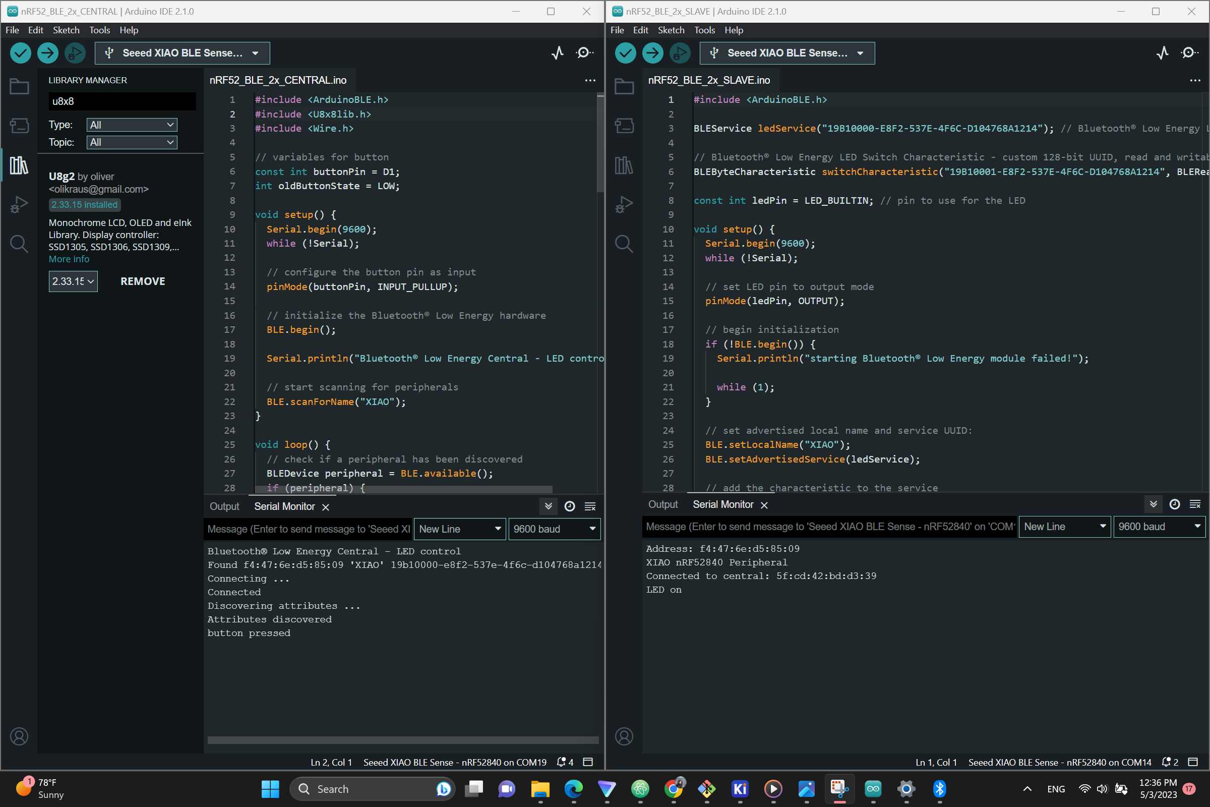 Fig. Two XIAO nRF52840 control LED via BLE.
Final Videos
Problems
- there is no actual .bin files for ESP32C3 for MicroPython and the examples to make the server and scanner from ESP32 library dont work for ESP32C3 -> I used Arduino IDE this time instead MircoPython
- although both ESP32C3 and nRF5240 use Bluethooth it was difficult to find any resources how to make them communicate with BLE/LE -> I used two nRF5240
- nRD5240 changes ports while compilining and uploading code with Arduino -> I don’t know how to fix it, I kept changing the port selection for the board, but later noticed that it uploads the code regardless this issue
Files
Xino Board 1 with ground wire board1 - with ground wire - kiCad + fabrication files
Xino Board 2 with ground plane board2 - with ground plane - kiCad + fabrication files