Week10. Machine Building
| Assignment | |
|---|---|
| group | design a machine that includes mechanism+actuation+automation+application; build the mechanical parts and operate it manually; document the group project link |
| individual | document your individual contribution |
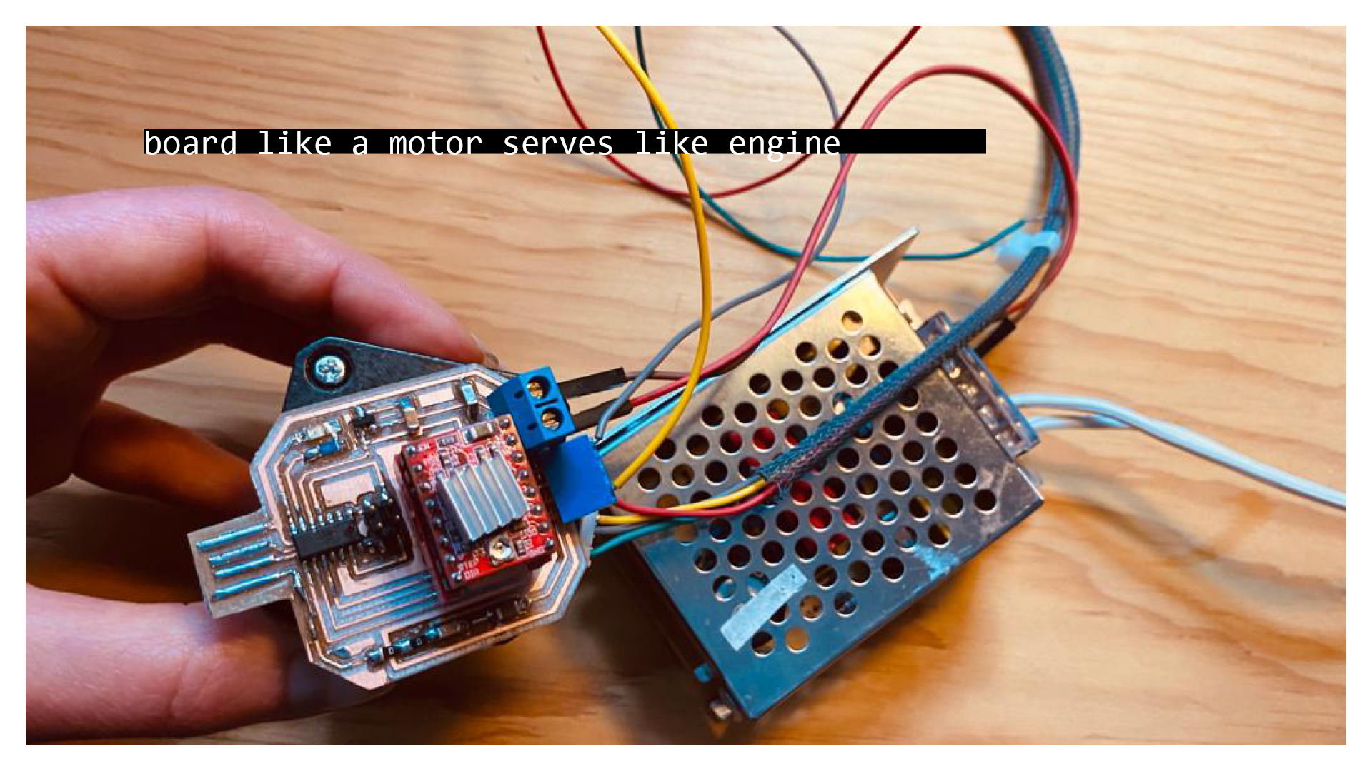
Photo of the week
My role in the group Assignment
- design, make and integrate electronics for controlling stepper motor with external power supply
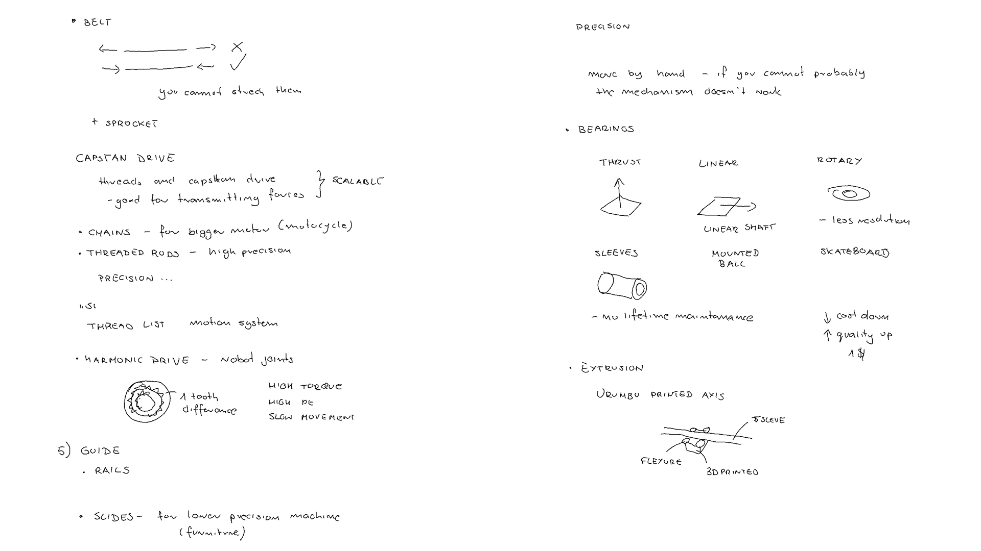
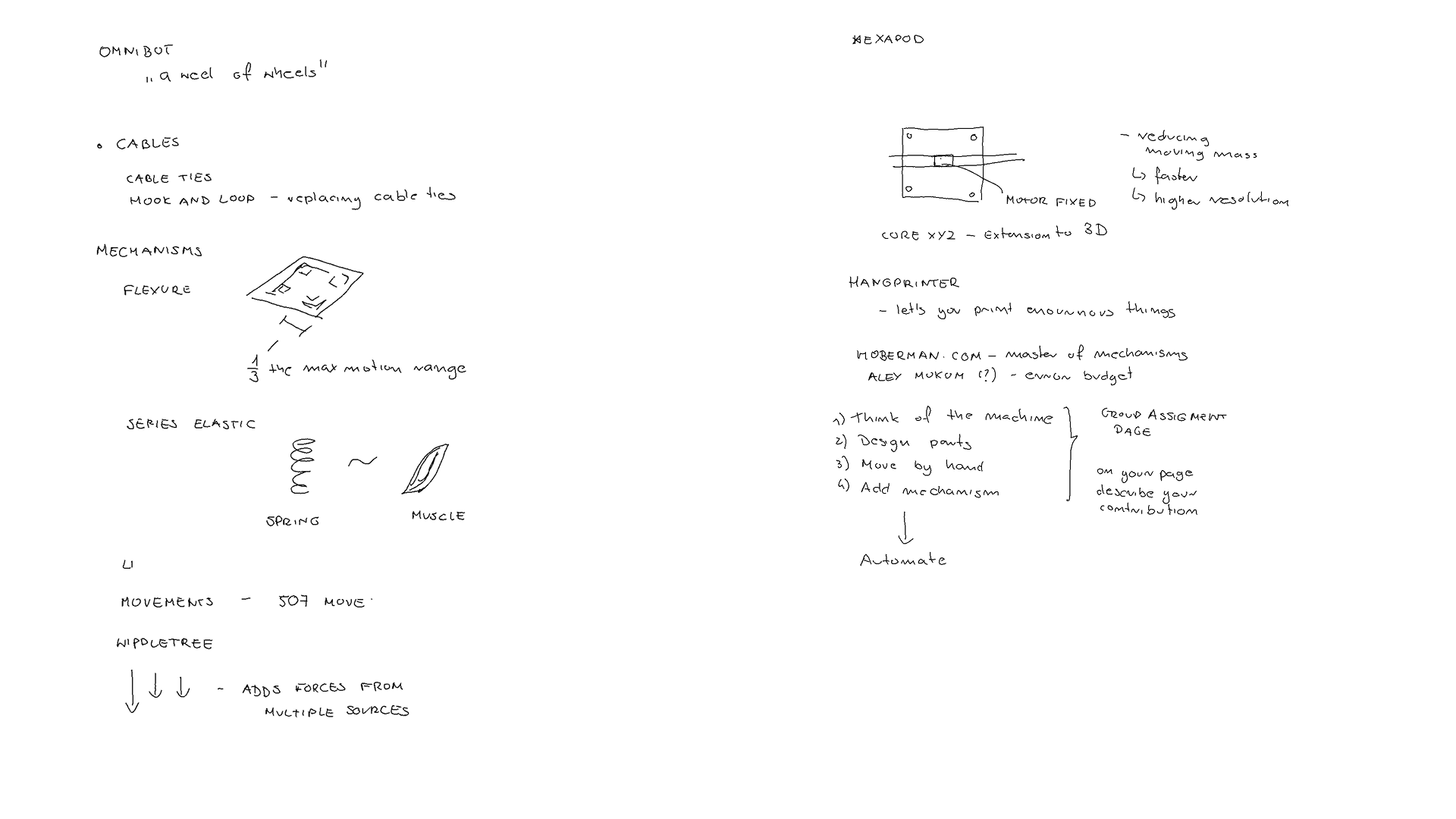
Lecture Notes
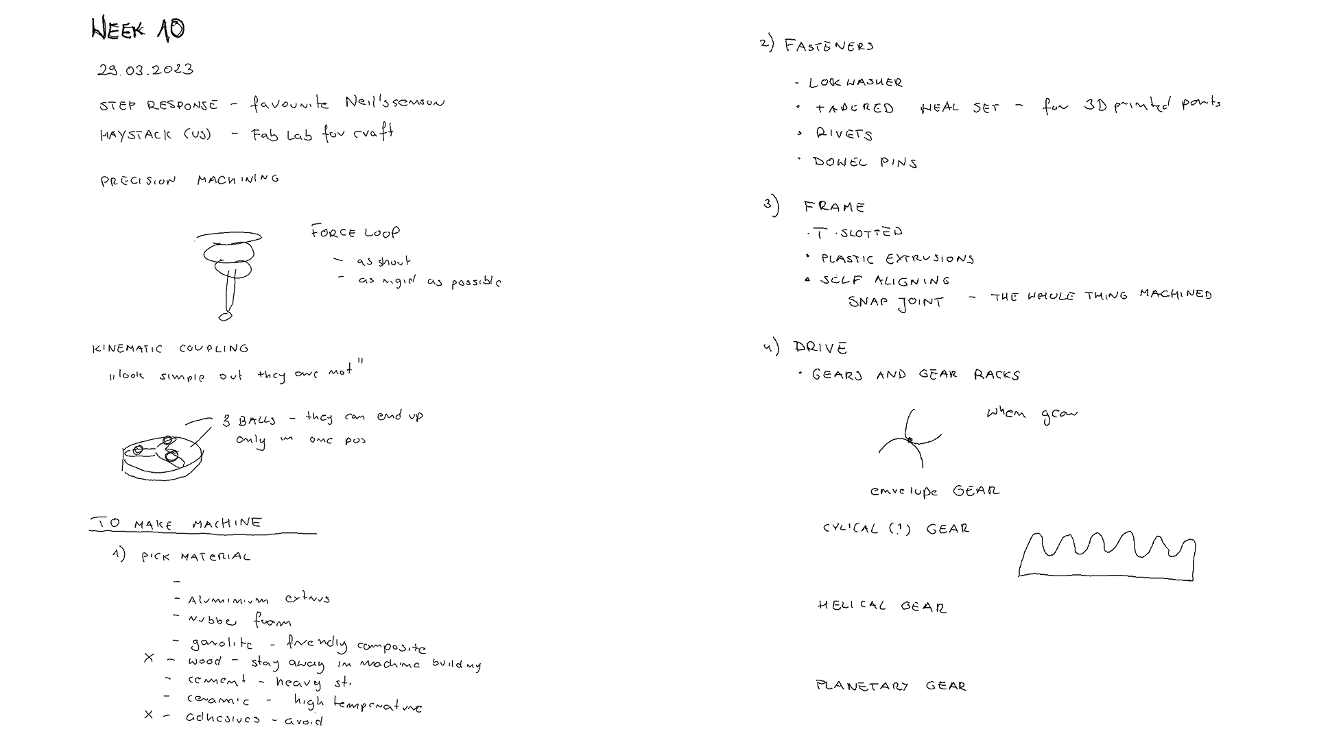
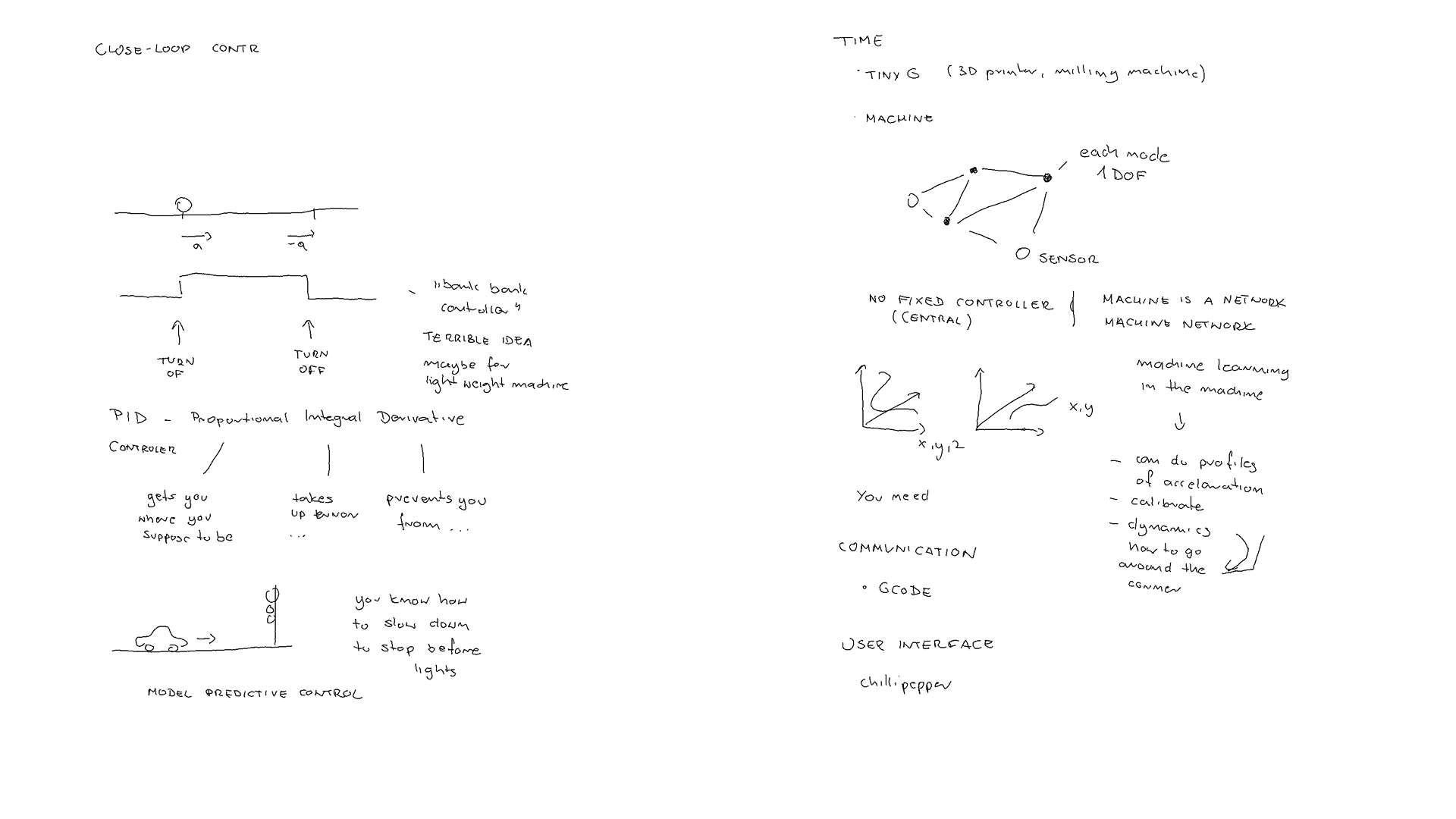
Lifting Mechanisms
The power consumption measured with method described:
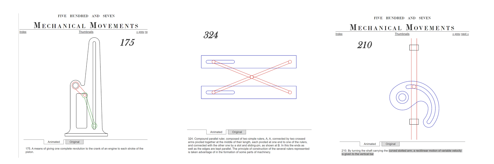 Fig. Vertical movement mechanism. Source: http://507movements.com
Board Examples for the external power supply
I have reviewed examples of the PCB boards with external power supply:
-
http://archive.fabacademy.org/archives/2016/fablabtrivandrum/students/369/w13/output_device.html
-
http://fab.cba.mit.edu/classes/863.04/people/ztaylor/5/asst5.html
-
http://fab.cba.mit.edu/classes/863.04/people/ztaylor/5/asst5.html
-
https://fab.cba.mit.edu/classes/863.22/EECS/people/Noah/Week9.html
The most useful for understanding general workflow of connecting power supply - notes in the figure below.
https://fab.cba.mit.edu/classes/863.22/EECS/people/Noah/Week9.html
Board Properties
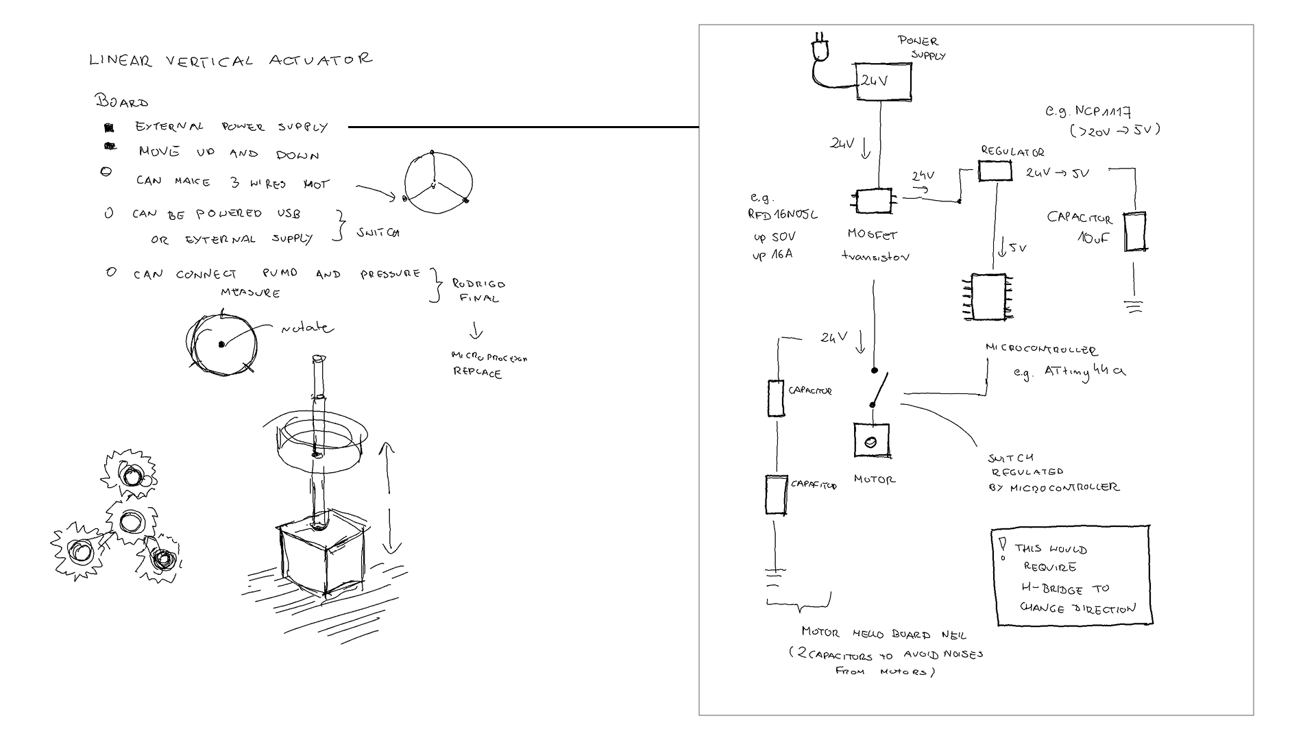 Fig. Left: Board Properties. Right - schematic for plugin external power supply.
-
can use external power supply to one step motor
-
can be powered both by USB or external supply (switch?)
-
can make 3 wires hot
-
optionally can connect air pump and pressure sensor (in case of the mechanical actuator failure, can use )
I realized that for the control of the direction the design requires the H-Bridge.
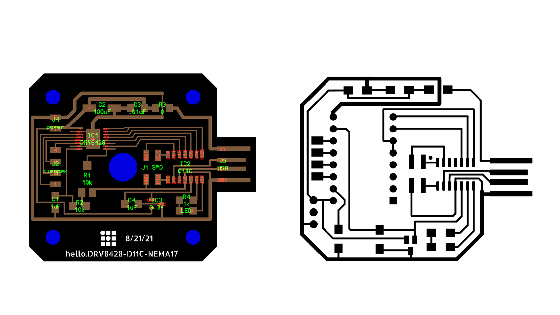
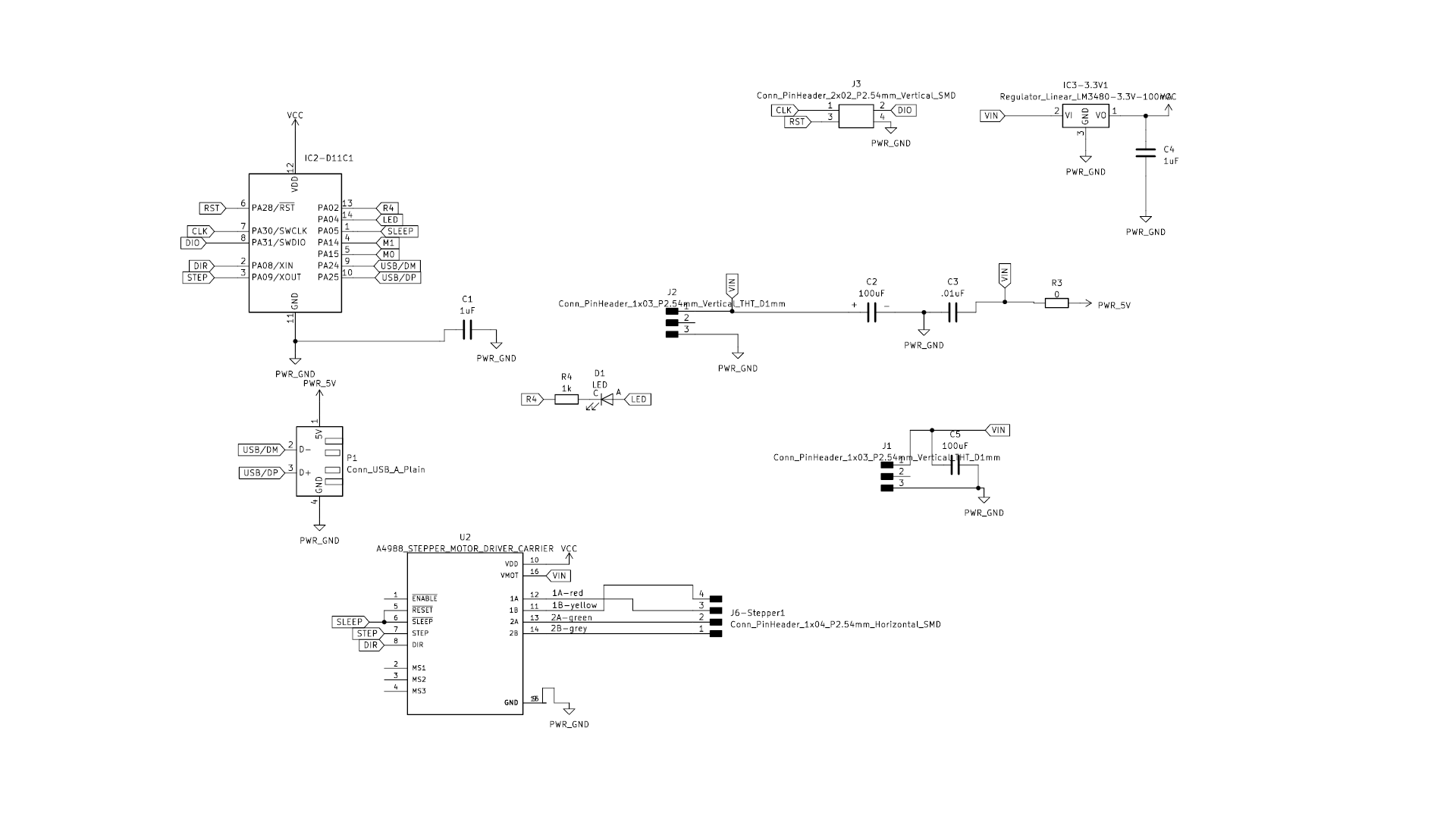
hello.DRV8428-D11C-NEMA17 &
Therefore, I came back to look for examples with control movement and a power supply. And I found this great example by Neil dedicated to the motor stepper we intended to use.
-
hello.DRV8428-D11C-NEMA17: http://academy.cba.mit.edu/classes/output_devices/DRV8428/hello.DRV8428-D11C-NEMA17.png
-
gitlab resources: https://gitlab.cba.mit.edu/neilg/urumbu/-/tree/master/serialstep
-
python design interface: https://leomcelroy.com/svg-pcb/?file=hello.DRV8428-D11C-NEMA17.js
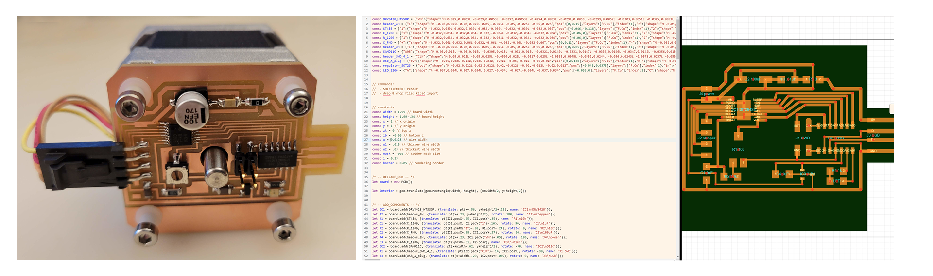 Fig. Left: Inspiring design. Right - my trials to adjust it for fabrication in https://leomcelroy.com.
This design was not possible, as the min. width of the tracks for the machines in local node - 0.4mm and the Neil’s design is 0.1mm. Moreover driver DRV8428_HTSSOP was not in the stock.
For finding alternative ways of producing PCB with such thin wires: https://www.youtube.com/watch?v=5nXNK0cr5v. Anyhow without the all components in stock, it wouldn’t be possible to make the board on time for this assignment.
Board design with A4988 STEPPER MOTOR DRIVER
To make sure we can finish assignment on time, I have to use the A4988 STEPPER MOTOR DRIVER in the design of PCD. I reviewed the Rodrigio Shiordia design of the board for the Stepper Motor NEMA 17.
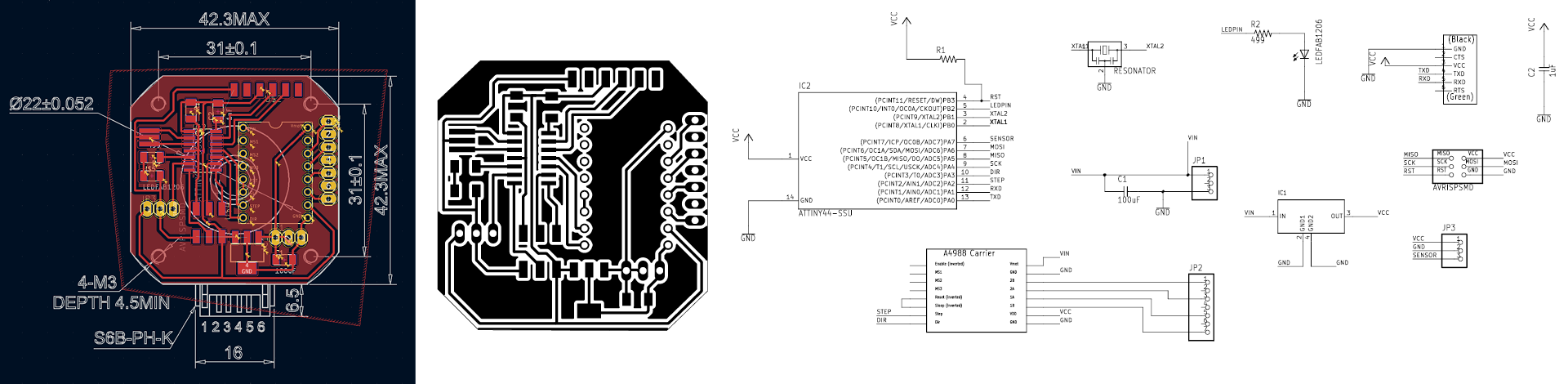 Fig. PCB with Attiny44 and A4988 STEPPER MOTOR DRIVER fitting to the step motor layout.
This design was possible, however it would be better to use SAMD11C and USB communication.
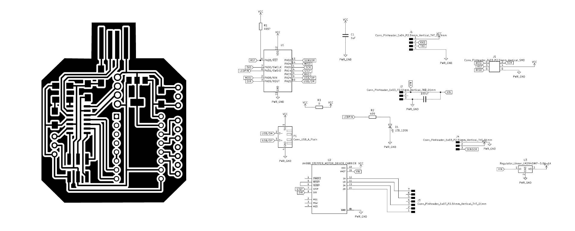
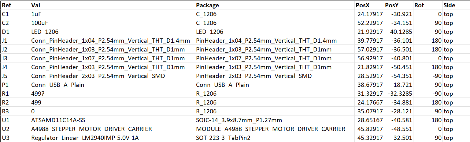
Board design with A4988 STEPPER MOTOR DRIVER & SAMD11C
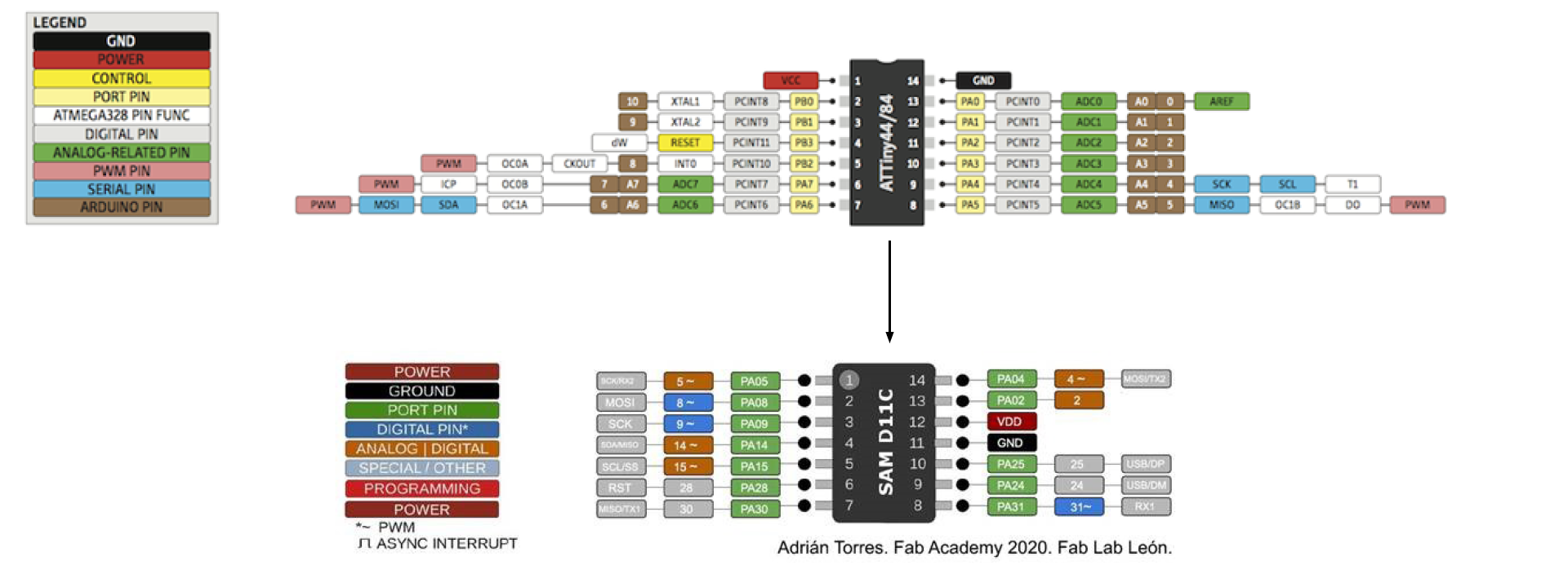
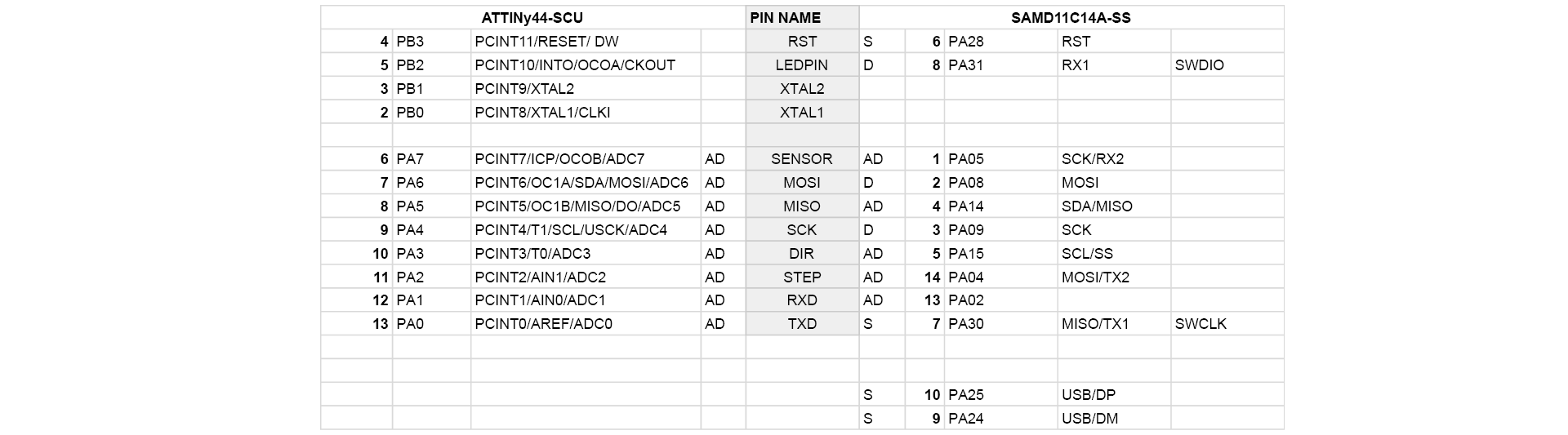
Migration from Attiny44 to ATSAMD11C14A
PCB DESIGN - FAILED
 files KiCAD download: kicad files
The CNC machining file with the 0.4 track width and 0.4 clearance (due to the Easter break I had to try to make it done on the machine outside Fab Lab at university). Moreover, meantime I detected a mistake with the USB +/- connections to the SAMD11C)
FINAL PCB DESIGN
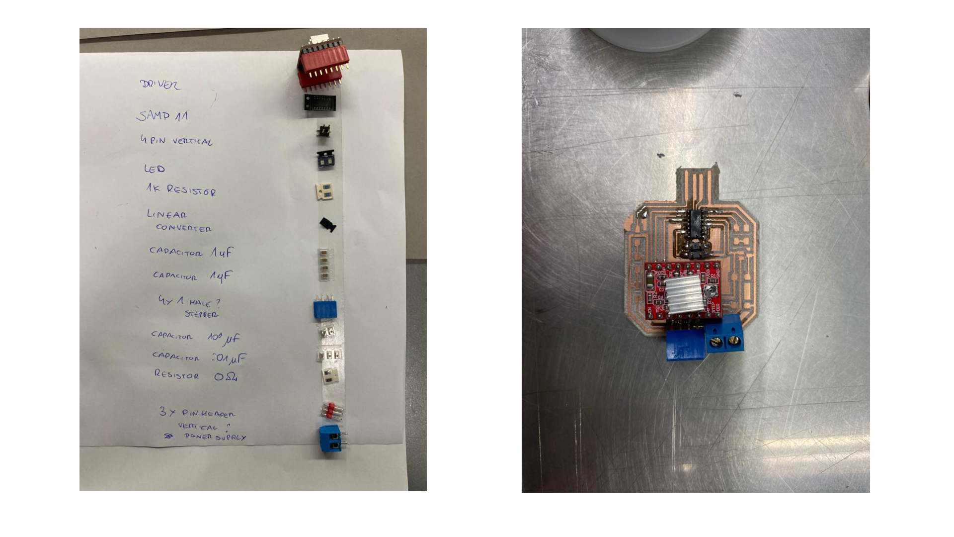
Parts
-
Step Motor: Nema 17 External 48mm Stack 0.4A Lead 2mm/0.07874” Length 300mm specification
-
Stepper Motor Driver: A4988 STEPPER MOTOR DRIVER CARRIER specification
Files
files KiCAD download: FINAL kicad files - produced board
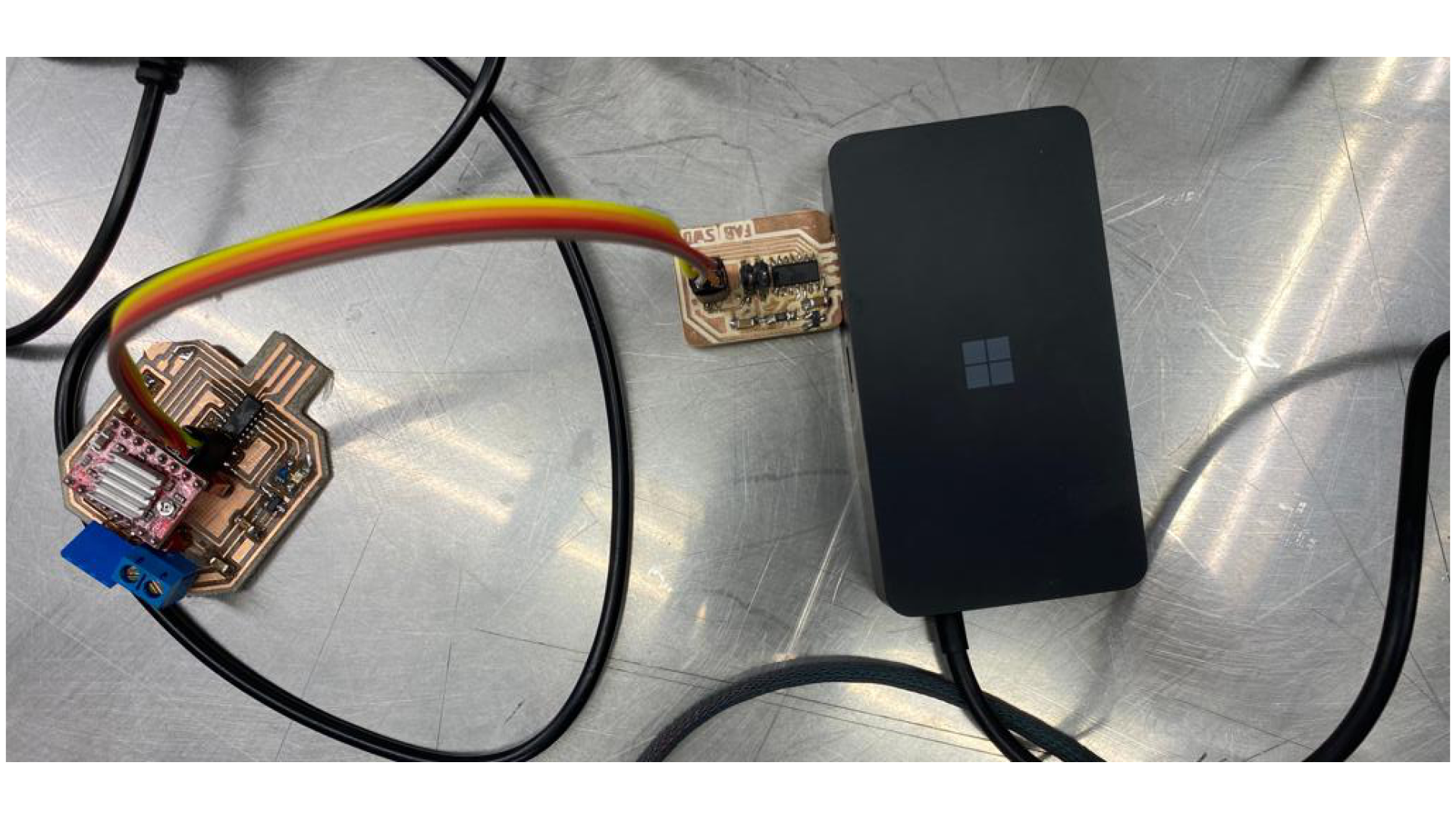
Loading Bootloader
To load bootloader I followed the instructions provided by Adrian Torres here
Arduino hello Files
As the diode was soldered in the opposite direction to the design.