Week09. Output Devices
| Assignment | |
|---|---|
| group | measure the power consumption of an output device link |
| individual | add an output device to a microcontroller board you’ve designed, and program it to do something |
Photo of the week
Lecture Notes
Take aways from the group Assignment
The power consumption measured with method described:
-
the higher rotation speed - more power consumption
-
Power (Watts) = Voltage (Volts) x Current (Amps)
-
S3003 servo: low freq: 5.0V x 0.125A = 0.625W, high freq: 5.0V x 0.3A = 1.5W max. 5.0V x 0.7A = 3.5W
-
SG90 digital servo: low freq: 5.0V x 0.1A = 0.5W, high freq: 5.0V x 0.3A = 1.5W max. 5.0V x 0.5A = 2.5W
| Output Type | Sensor |
|---|---|
| digital (discrete) | Alarms, Control relays, Fans, lights, horns, valves, Motor starters, solenoids |
| analog (contiunous) | any? |
Output devices
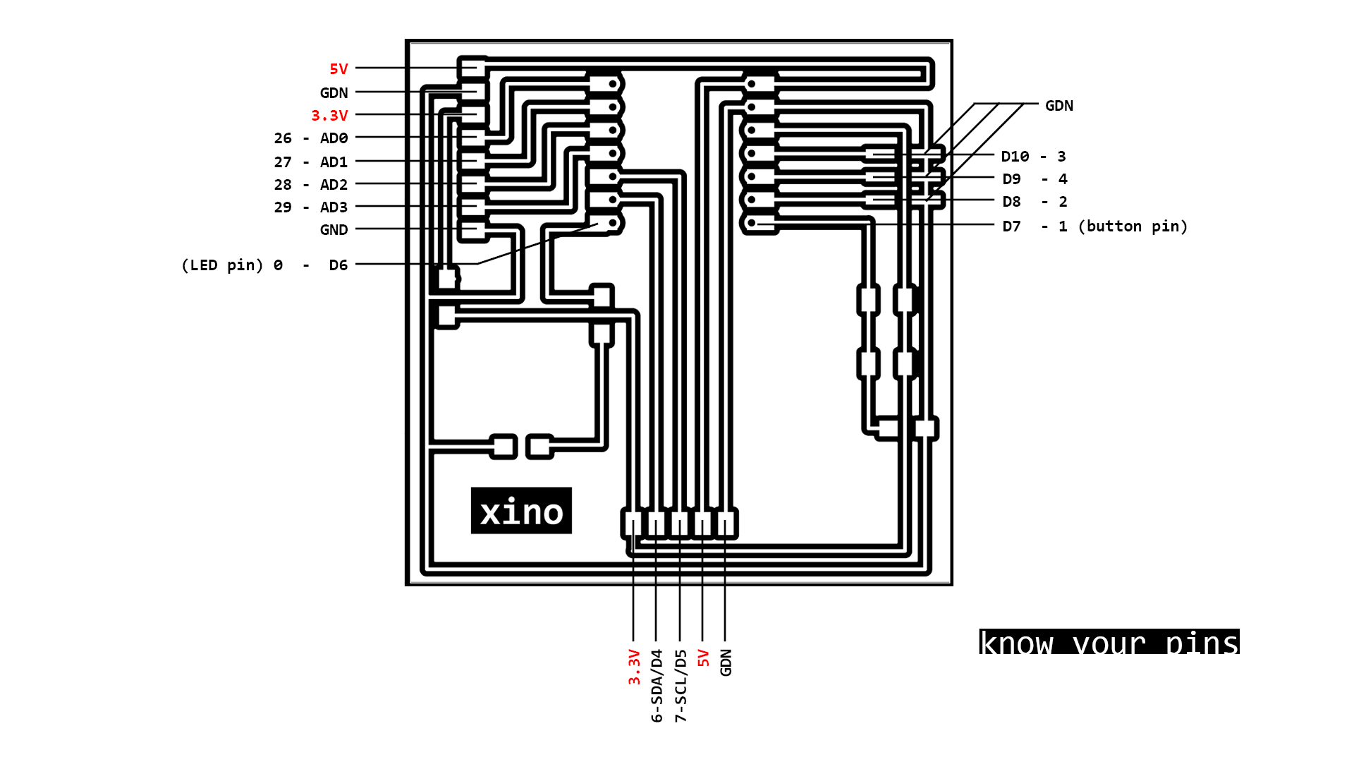
I have started with preparing the below illustration (photo of the week) to have better understaning of the pin layout.
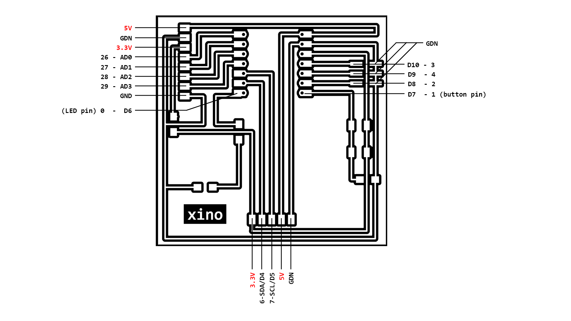 Fig. The schematic of the pin connection of the board to connect OI devices.
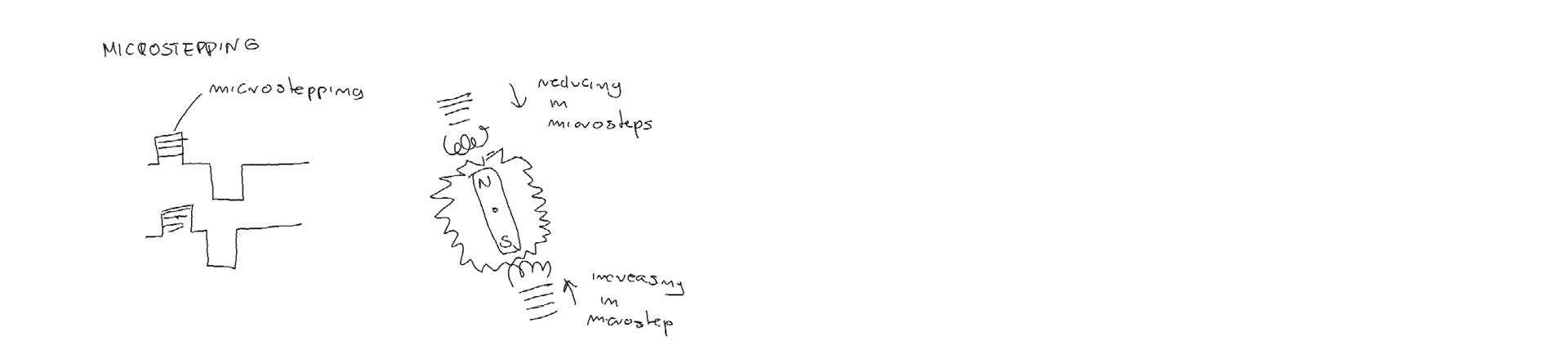
Step motor
Servo Futaba S3003 producent specification Voltage range: 4.8V - 6.0V maximum current draw: 700mA at 4.8V and 830mA at 6V.
SG90 digital servo producent specification Operating voltage: 4.8v maximum current draw: 500mA at 4.8V
Code MicroPython
MicroPython Stepper Motor - rotate with specified angle - based on the examples
from machine import Pin, PWM
class SERVO:
    def __init__(self, pin):
        self.pin = pin
        self.pwm = PWM(self.pin)
    def turn(self, val):
        self.pwm.freq(100)
        self.pwm.duty_u16(int(val/180*13000+4000))

p = Pin(6, Pin.OUT)

s = SERVO(p)
s.turn(0) # 0 - moves it to 0 position, steps 30, 60, 90
MicroPython Stepper Motor - generated by GPT chat as an answer for micropython code for continous rotation of the step motor
import machine
import time

# Define pins for stepper motor
step_pin = machine.Pin(6, machine.Pin.OUT) #default pin 5
dir_pin = machine.Pin(6, machine.Pin.OUT) #default pin 4

# Set initial direction
dir_pin.value(0)  # 0 for clockwise rotation, 1 for counterclockwise

# Set up PWM for controlling speed
pwm = machine.PWM(step_pin)
pwm.freq(200)  # Set PWM frequency to 1 kHz, set frequancies 200,500,1000,2000,5000

# Rotate motor continuously
while True:
    pwm.duty_u16(32768)  # Set duty cycle to 50%
    time.sleep(0.001)  # Wait for some time to allow motor to move
New Board designed
During testing the board produced in week08 I noticed that the swith button doesn’t work correctly.
- redesigning the button trases layout
- min. trace width: 0.6
- clearnace - 0.8 mm
- pad sizes: 3.0x1.8mm (pin headers and microcontroller) 2.2 x 1.8mm (resistors and LED), 2.6 x 1.8mm ( button), 3.15mm x 1.2mm - vertical pin header (-Right click on pad -> Properties -> change size in the window -Right click on a modified pad -> Push pad properties on other pads -> Change pads on current)
- removing not necessary Cu layer for easier soldering of the components
footprint
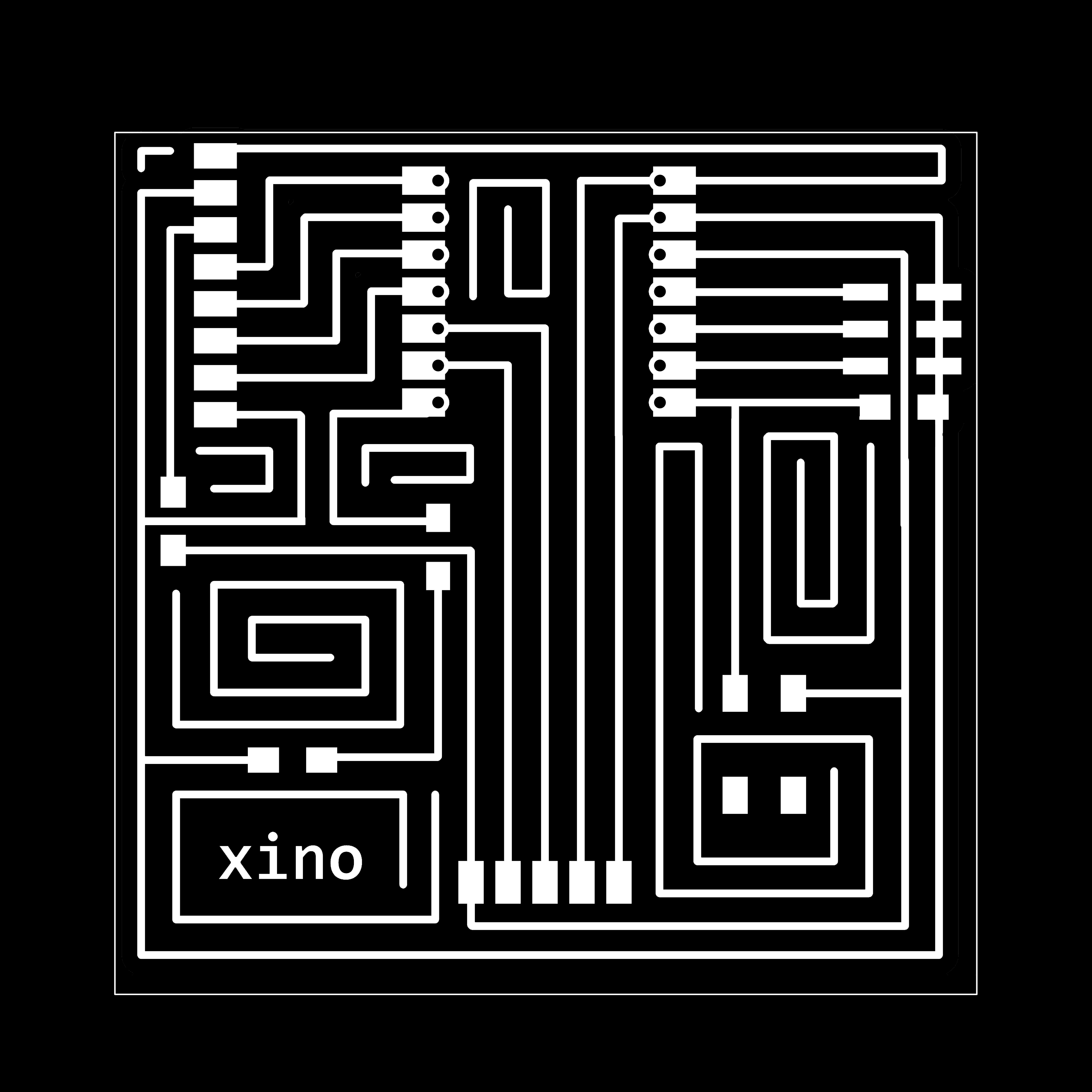 Fig. The new PCB board traces.
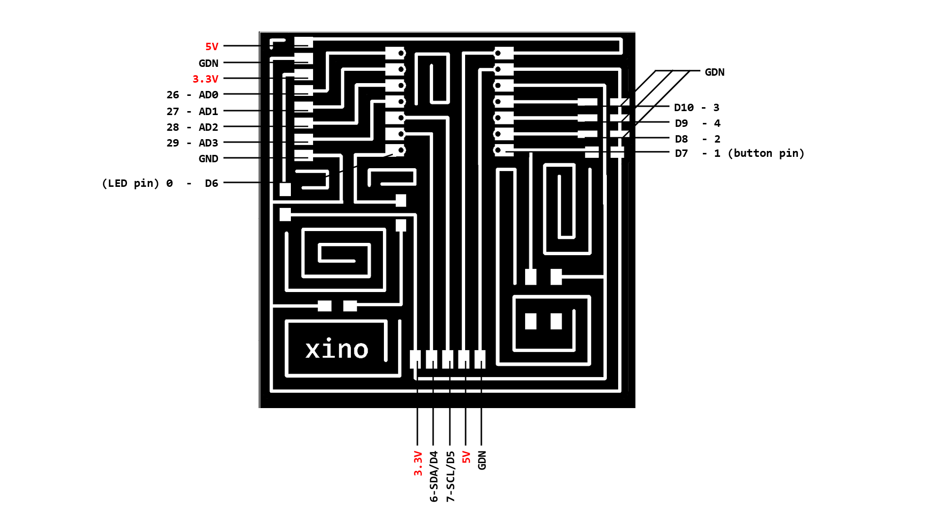 Fig. The schematic of the pin connection of the new board to connect OI devices.
 Fig. The schematic model and case for the new board.
The button works!
With help of my Instructor Rodrigo Shiordia, the button was fixed, and it works without the resistor connected before the button (?)
MicroPython Bliking LED with a Button
from machine import Pin

button = Pin(1, Pin.IN, Pin.PULL_UP) #setup pin where the button is connected
button.irq(lambda pin: InterruptsButton(),Pin.IRQ_FALLING)
led = Pin(0, Pin.OUT) #pins for RP2040 LED: 17- RED, 16- GREEN, 25- BLUE
tmp = 0

def InterruptsButton():
    global tmp
    tmp = ~tmp
    led.value(tmp)
while True:
    pass
Problems/Questions/Dilemas
- The motor vibirates and not rotates at some frequancies. Why?
- Does the swith button really need a resitor?
Files
desing files: Xxino - KiCAD