Week05. 3D Scanning and Printing
| Assignment | |
|---|---|
| group | test the design rules for your 3D printer(s) link |
| individual | design and 3D print an object (small, few cm3, limited by printer time) that could not be made subtractively, 3D scan an object (and optionally print it) |
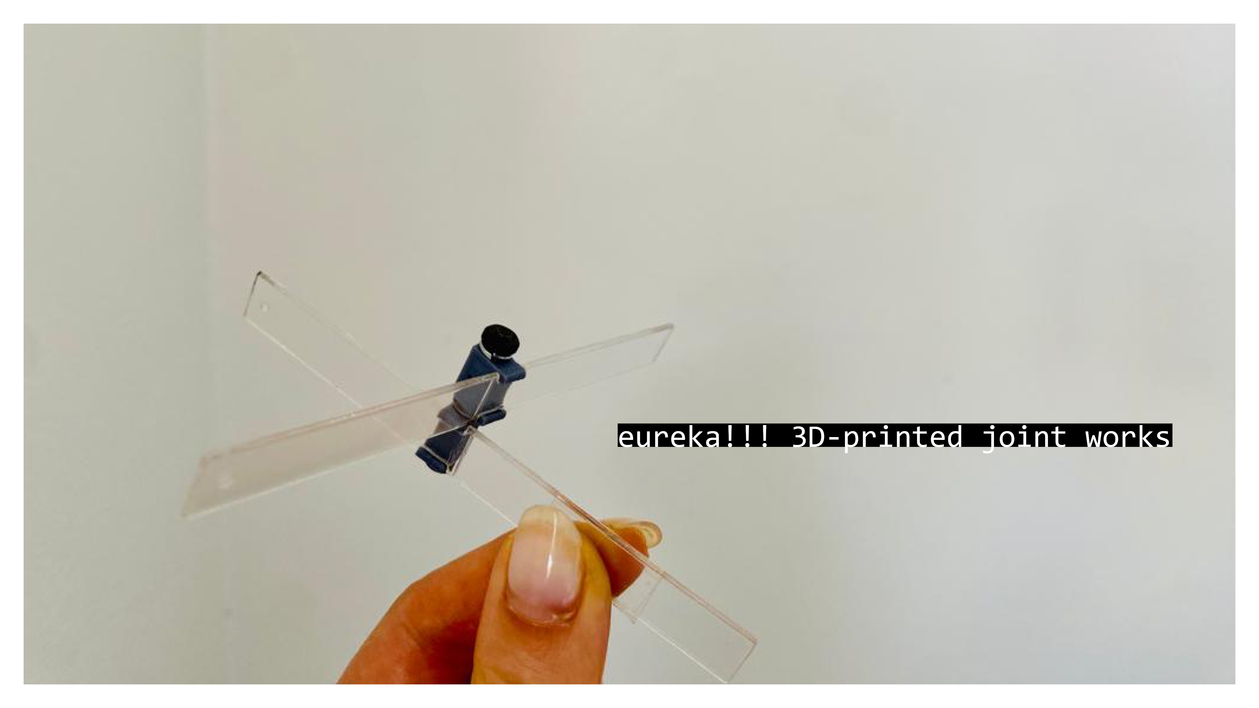
Photo of the week
Take aways from the group Assignment
- there are special test prints files for testing 3D printers like this one
- it is worth to consider the vertical vs horizontal positioning of the piece
- it’s hard to rely on smaller precision than 1mm (as small imperfections make elements not fit)
3D Kinetic Joint Design
Video. Morphology of kinetic asymptotic gridshells - research by Eike Schling.
The assymptotic gridshells can work as kinetic structures, if the joint allows it. Inspired by work done by Eike Schling (video above), which I saw at the Design Symposium Modelling in September 2022, I attempted to design my own kinetic joint for the model structure.
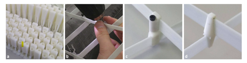
Fig. The GRP lamellas were connected by hand (b) with 3d printed sleeves and M3 bolts (c). The sleeves are batch-printed (a) with a Form 3 Stereolithography (SLA) printer. A second, rigid sleeve ( d) is used as internal restraint. (Eike & Schikore, 2022)
I started from reading more about preseted above project. The kinetic joints, which Schling named “sleeves”, where printed with SLA and connected using 3M 20mm bolts:
“The physical experimental models are designed and constructed from glass fibre reinforced plastic lamellas (1 x 10 mm) and joined laterally on two levels using 3D-printed sleeves. M3 steel bolts (20 mm) create the scissor joints, which allow rotation around the normal axis. The joints are located with a 3 mm offset to the theoretical intersection points due to the lateral connection. The positions are marked by hand and the 3D joints are threaded and glued onto the glass fibre lamella.” (Eike & Schikore, 2022)
I found one drawback about this joint design - the positions of the joins had to be marked by hand and the sleeve-joints manually glued at the right place on the lamella. I came up with the idea to design a joint, which has “click”, no glue connection (therefore can be also reused in the other models), and which is placed exactly in the cutout in the lamella - making it easy and precise to assemble. The first sketch of the solution below.
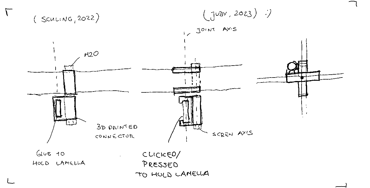 Fig. Click 3D-printed joint idea.
First I made a few static models to test the idea in 3D.
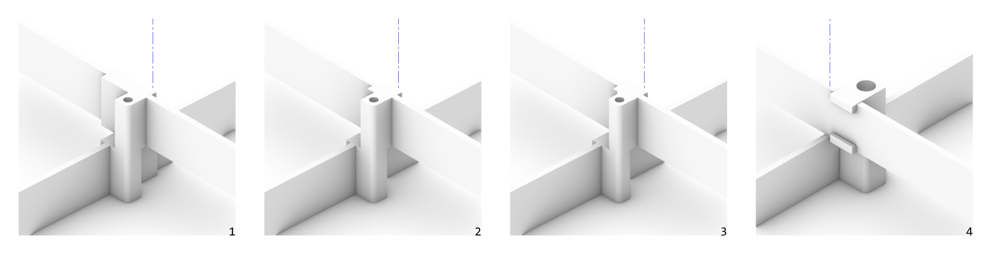 Fig. Development of the static model. 1 - the clips in the middle of the joint axis, 2 - clips made shorter, edge not touching the axis, 3- some more fillets added for smoother desing and easier fabricaiton, 4 - a model with more up to scale screw size :).
Preparation of the static 3D models let me figure out the right parameters that should control the algoritmic model.
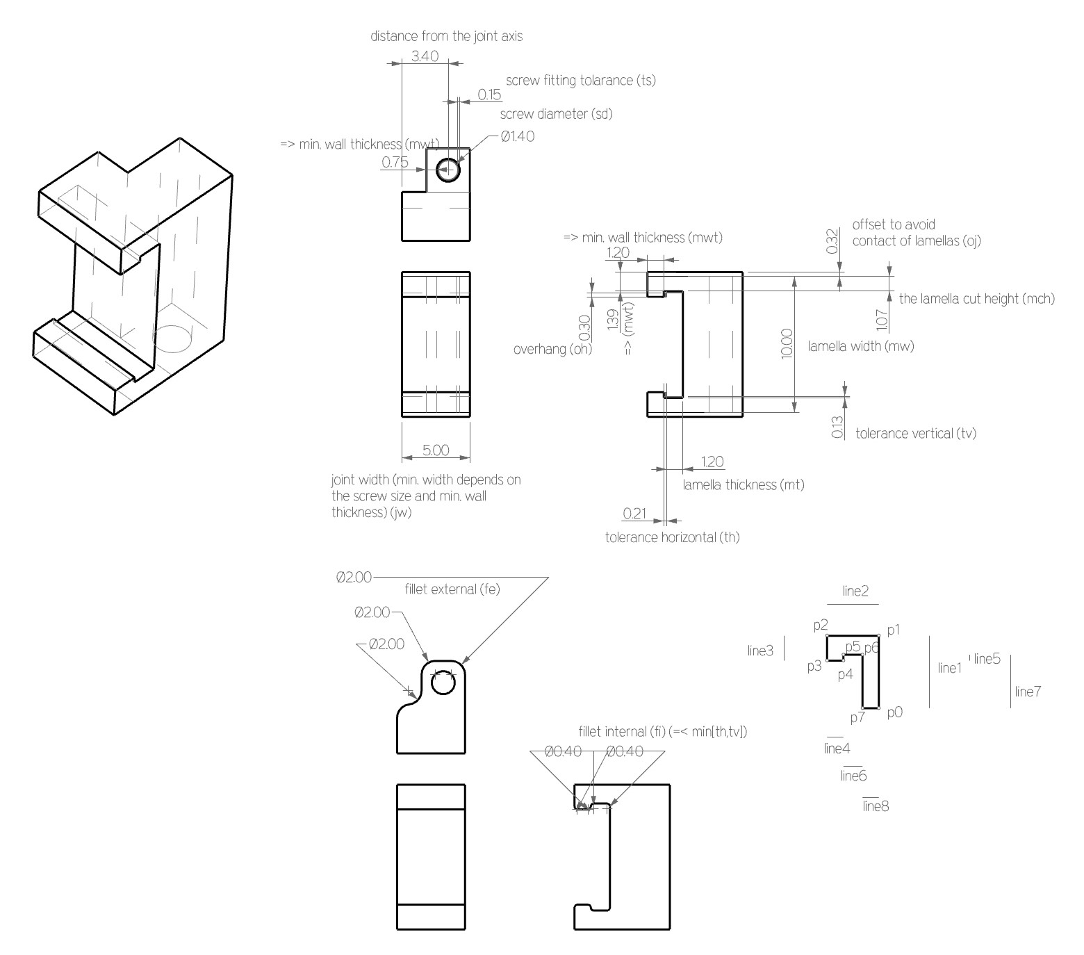 Fig. Design parameters for kinetic joint.
__author__ = "judycurie"
__version__ = "2023.02.24"

import rhinoscriptsyntax as rs
import ghpythonlib.components as gh
import math

#geometry rules
if fi> th or fi>tv:
    fi = min(tv,th)

point = gh.ConstructPoint(0,0,0)
plane = gh.XYPlane(point)
circle = gh.Circle(plane, sd*0.5 + ts)
rec = gh.Polygon(plane, (sd*0.5+ts+mwt)* math.sqrt(2), 4, 0)['polygon']
rec = gh.Rotate(rec, math.pi/4, plane)['geometry']
rparams = gh.Discontinuity(rec,1)['parameters']
rec = gh.Fillet(rec,rparams[0],fe)['curve']
rparams = gh.Discontinuity(rec,1)['parameters']
rec = gh.Fillet(rec,rparams[0],fe)['curve']
rparams = gh.Discontinuity(rec,1)['parameters']

srf1 = gh.BoundarySurfaces([rec,circle])
vec1 = gh.UnitZ(0.5*mw+oj)
ext1 = gh.Extrude(srf1, vec1)

p0 = gh.ConstructPoint(0,-(0.5*sd+ts+mwt),0)
p1 = gh.Move(p0,gh.UnitZ(0.5*mw+oj))['geometry']
p2 = gh.Move(p1,gh.UnitY(-(mwt+mt+th+mwt)))['geometry']
p3 = gh.Move(p2,gh.UnitZ(-(mwt+tv+oh)))['geometry']
p4 = gh.Move(p3,gh.UnitY(mwt))['geometry']
p5 = gh.Move(p4,gh.UnitZ(oh))['geometry']
p6 = gh.Move(p5,gh.UnitY(mt+th))['geometry']
p7 = gh.Move(p6,gh.UnitZ(-(0.5*mw+oj-mwt-tv)))['geometry']

polyline = gh.PolyLine([p0,p1,p2,p3,p4,p5,p6,p7],True)
params = gh.Discontinuity(polyline,1)['parameters']

pts = [p0,p1,p2,p3,p4,p5,p6,p7]
filletpts = [p2,p3,p4,p5,p6]
filletcrv = gh.Fillet(polyline,params[2],fi)['curve']
for i in range(len(filletpts)-1):
    newparams = gh.Discontinuity(filletcrv,1)['parameters']
    filletcrv = gh.Fillet(filletcrv,newparams[0],fi)['curve']

if jw == None:
    jw = sd+2*mwt+2*ts
srf2 = gh.BoundarySurfaces(filletcrv)
srf2 = gh.Move(srf2, gh.UnitX(0.5*sd+mwt+ts))['geometry']

vec2 = gh.UnitX(jw)
ext2 = gh.Extrude(srf2, -vec2)

geo = gh.SolidUnion([ext1,ext2])
geom = gh.Mirror(geo, gh.XYPlane(point))['geometry']
geo = gh.SolidUnion([geo,geom])

fabparams = ["sd "+str(sd), "ts "+ str(ts), "mwt "+ str(mwt), "mw "+ str(mw), "oj "+str(oj) , "th "+str(th), "mt "+ str(mt), "oh "+str(oh), "tv "+ str(tv), "fi " +str(fi), "fe "+str(fe), "jw "+ str(jw)]
Why the joint cannot be made substractively? The model of the kinetic joint cannot be made substarctively with a 3-axis machine. There is a little chance it could be made by the 5 or 6-axis robot arm, if the tool size would allow it.
3D printing
I prepered a custom Python script for the generation of the 3D joint model. I generated 3 models to test with different design parameters.
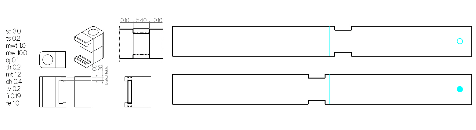
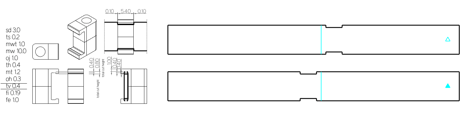
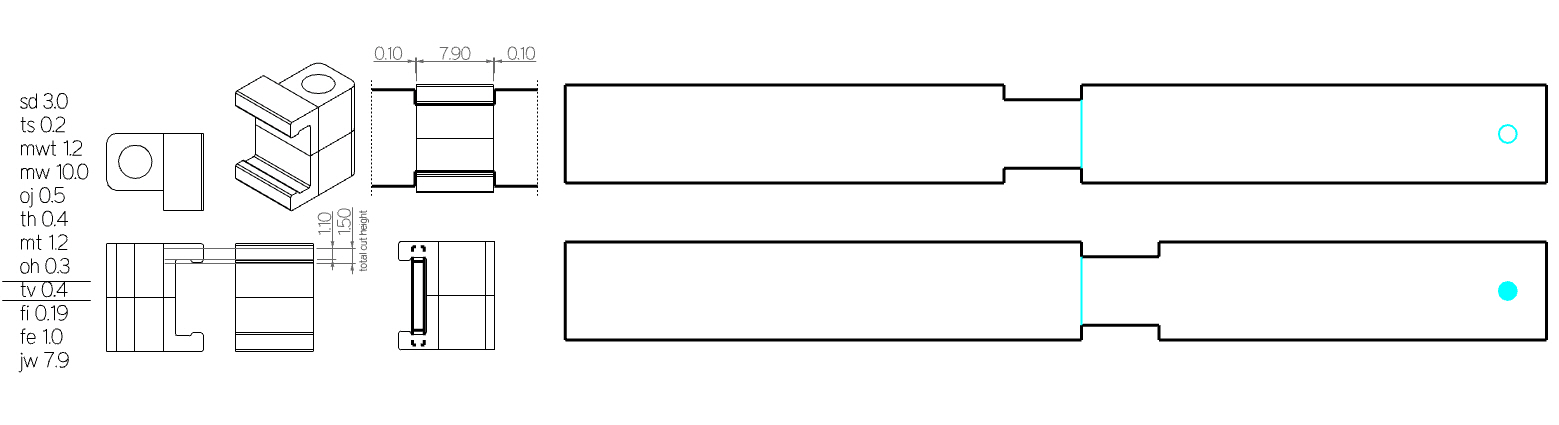
I prepared the file for printing exporting the .stl files directly from Rhino. The pairs of connectors and the matchinh laths were marked for recognistion. The final fabrication model contains the 3 versions of the kinetic joints printed in vertical and horizontal positions - to test what works better for the joint geometry.
Printer and Settings
Printer Model: 3DWOX 3DWOX1 | Sidoh 3D Printer
Material: PLA grey
Printer Settings: (Default): exact settings
Printing file: as in the below picture.
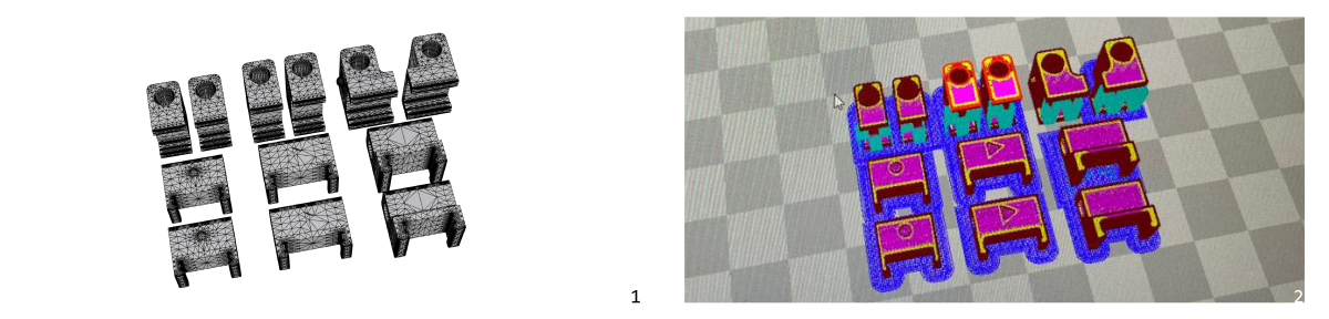 Fig. 1- the .stl file, 2 - the gcode.
Printing results.
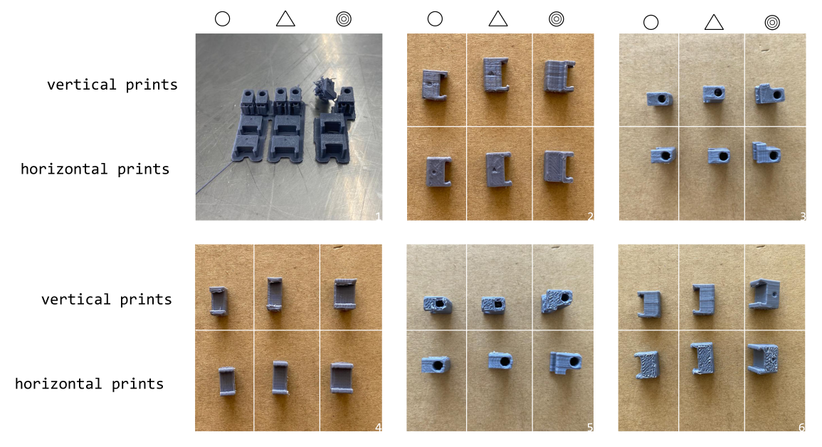 Fig. The printed joints in the vertical and horizontal orientation. 1 - the perspective of the prints out from the printer, 2 - left view, 3- top view, 4- front view, 5 - bottom view, 6 - right view.
| Feature | Vertical Print | Horizontal Print |
|---|---|---|
| ease to remove from bottom material | + | - |
| support material easy to remove | + | na |
| screw fit | + (a bit tighter compared to horizontal print & in same samples the bottom-bed material was making it hard to push through) | ++ just right for the rotation |
| fit to the lath (click part) | + (sometimes support material not removed correctly causes misfit) | ++ fitting is smooth as designed |
| visual drawbacks | bottom not visible part (however it can cause friction while rotating) | side part - without effect on mechanism |
In general despite visual drawback as the right side of the joint is visible after mounting and difficulty from detaching horizontally printed parts from the bottom-bed material, the horizontal orientation is more accurate for the purpose of the design. The difficulty of disattaching the part from unnecessary bottom-bed material can be easely overcome by moving the mesh a little bit above the horizontal plane (causing adding some easily removable support material) or adding some thin legs (also resulting with easy to remove support material added).
3D scanning
As I arrived to the Mexico City, my luggage lost one of the small plastic legs (Fig. below). I intended to make a scan of one of the remaining elements and produce a digitally-fabricated replica.
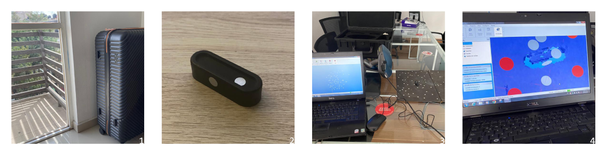 Fig. 1 - the object for scanning idea, 2 - the object to be scanned with markers, 3- scannig setup, 4 - the scanning result.
Video. Scanning process.
The result of the 3D scan was not enough to make a print out of it. I was trying to increase the scan quality by increasing the resolution to 1mm and power of the laser to 100%. Despite the efforts still the resulting mesh was too rought to be used as input for printing.
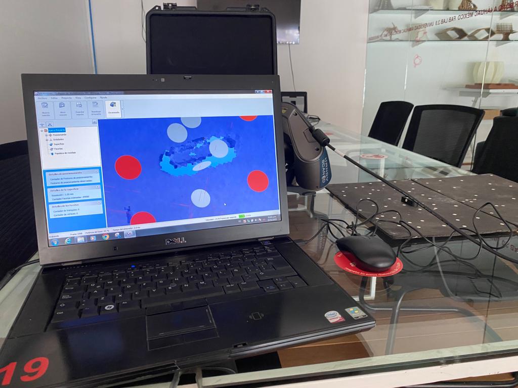 Fig. Scanning failure model.
Further work
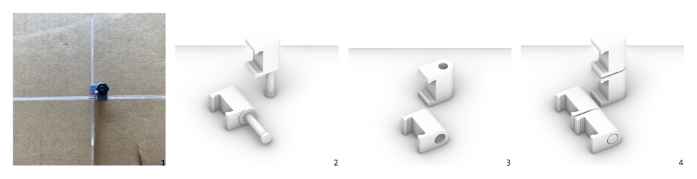 Fig. 1 - introducing the blocking possibility, 2 - joint without a screw- top part, 3 - joint without a screw- bottom part, 4 - joint without a screw.
-
It would be great if the joint would allow to block it at 90 deg (to stop the kinetic behaviour and keep the final shape in place).
-
Maybe it would be possible to create a model where the joint is composed of 2 parts which are already connected together (without a screw).
-
Definitely SLA printing would help for print precision and maybe it would show better friction property to keep lamellas in place.
-
Testing of the clip joint should be conducted on scaled- model, as with the stress caused by bending the stripes around 2 axis can casue that the lamella simply jumps out of the joint.
-
Writing the script directly with rhinosyntax.
Conclusions
Summary of the model parameters after 3D printing tests
| Model Parameter | FDM PLY |
|---|---|
screw diametersd |
3mm - working fine (for screw with the thread 2.8mm) with the below tolerance |
tolerance screwts |
0.2mm - just fine |
| min. wall thickness | 1mm working fine in all parts of the model, maybe it can go even lower for smaller size of the joint (0.8mm) |
member width mw |
10mm its enough of width to cut put parts, anyhow can vary just avoiding stipes getting too narrow |
overhang joint oh |
0.1mm - works fine, could be to small for longer elements (they will touch during roatation, 1mm was too much |
tolerance horizontal th |
0.4mm was working fine with the internal fillets 0.2mm, th > 2fi |
tolerance vertical tv |
0.2mm -just fine, 0.4mm seemed to big, tolerance vertial has to be smaller than overhang parameter, tv< oh |
fillet internal (radius) fi |
0.2mm -just fine, fi< 0.5th |
fillet external (radius) fe |
1mm - just fine, fe < 0.5sd |
tolerance horizontal lamella thl |
0.1mm from each side worked perfectly |
Problems/Questions/Dilemas
-
The scanner was scanning also the background, therefore aquiring the mesh of the scanned object some “manual” post-processing is required.
-
Printing such small elements as a kinetic joint on FDM-PLA printer is a bit tricky.
Files
design files for 3D print: Connector Models - Rhino/stl/gcode