11. Input devices
input devices are something I have utilized in the past. In our group project where we created a coffee vending machine, my contribution besides from the code and logo was incroperating the lcd screen gui and three buttons connected to pulldown resistors to control it. This week, we would take that a step forward. The project I chose for this week was to integrate my past board with an infared sensor so that I could activate it with a remote.
Group Project
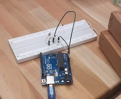
For the group project, we experimented with many of the sensors and other input devices found in the lab Using Arduino Unos and breadboards.
Before going to work, professor Goodman informed us of the different categories of input devices we would be using and how to utilize them. I had already used a button for a past assignment incorperating a pull down resistor to prevent the buildup of electrons affecting the output, but this time, I was introduced to a pull up resistor, the effective inverse which can easier to impliment due to arduino’s built in pinmode.
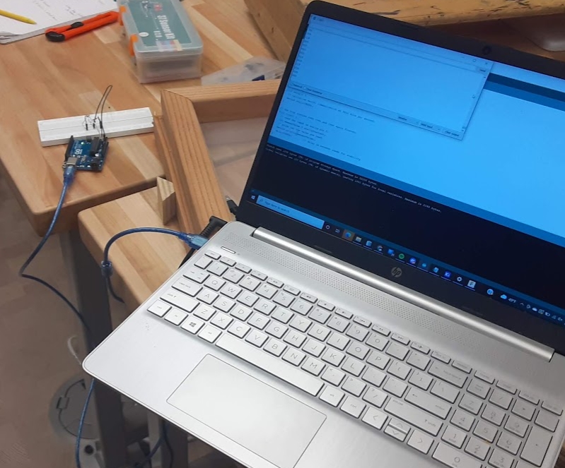
We wrote code on the arduino that could write the output of the sensor to either serial or an LED that we had connected to Arduno.
There are more than digital inputs, whose outputs are only one of two possible values. We were also given instruction on how to read analog inputs, which could output a range of values. For our in class example, we used a light resistor and temperature resistor, and monitored the resistance of the sensors after changes to light and temperature respectively.
Code used for reading sensors
const int analogInPin = A0;  // Analog input pin that the potentiometer is attached to
const int analogOutPin = 9; // Analog output pin that the LED is attached to

int sensorValue = 0;        // value read from the pot
int outputValue = 0;        // value output to the PWM (analog out)

void setup() {
  // initialize serial communications at 9600 bps:
  Serial.begin(9600);
}

void loop() {
  // read the analog in value:
  sensorValue = analogRead(analogInPin);
  // map it to the range of the analog out:
  outputValue = map(sensorValue, 0, 1023, 0, 255);
  // change the analog out value:
  analogWrite(analogOutPin, outputValue);

  // print the results to the Serial Monitor:
  Serial.print("sensor = ");
  Serial.print(sensorValue);
  Serial.print("\t output = ");
  Serial.println(outputValue);

  // wait 2 milliseconds before the next loop for the analog-to-digital
  // converter to settle after the last reading:
  delay(2);
}
Indivisual Project
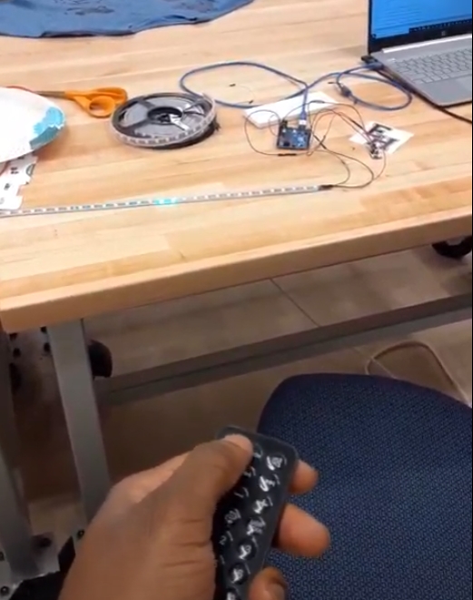
The project I chose for this week was to integrate my past board with an infared sensor so that I could activate it with a remote.
modifying previous project
Previously, I had made a board that operated a neopixel strip with the effect of a random color travelling throught the strip one pixel at a time at a random speed and direction. Luckily for me, I had coded this effect into one function that could be called any time. My plan was to call this function whenever the infrared reciever recieved a particular innput from a remote.
learning the infrared reciever
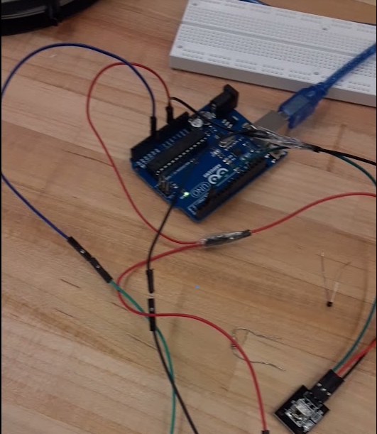 the first step I took for this project was to connect the IR receiver to an arduino and observe what was output as I pressed different buttons on different remotes. To do this, I printed an analog read of the pin of the reciever to serial. It was then I noticed that the output was the same every time regardless of which button I pressed. It turned out I had a fundamental misunderstanding of how the Infrared reciever was working. the reciever was not analog at all, but a digitial one that read data by the pattern of binary values flashed at the reciever in a very short time.
IRRemote library
The thing that helped me come to this conclusion was the realization that there was already arduino library support for infrared recievers. I then attempted the simple reciever example to send the data sent from the remote to serial, this ended in my desired result, a code that varied depending on the button that was pressed. I modified the example, setting up a neopixel strip and adding the spanStrip function to run whenever the power button on the remote was pressed. After that was successful on the arduino, I transferred the code to my mother board.