6. Electronics design
This week I worked on defining my final project idea and started to getting used to the documentation process.
Indivisual Project
Kicad
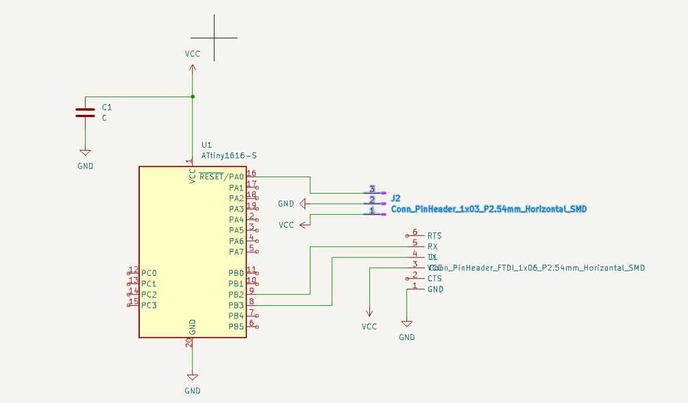
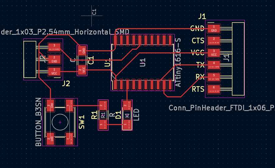
The first step to making the board is to design it in kicad. The components used to create this were an attiny 1616 microprocesor, an LED, a button, a resistor, capacitor, and 1 3 pin and 1 6 pin header.
mods
Useful links
Code Example
Use the three backticks to separate code.
// the setup function runs once when you press reset or power the board
void setup() {
  // initialize digital pin LED_BUILTIN as an output.
  pinMode(LED_BUILTIN, OUTPUT);
}

// the loop function runs over and over again forever
void loop() {
  digitalWrite(LED_BUILTIN, HIGH);   // turn the LED on (HIGH is the voltage level)
  delay(1000);                       // wait for a second
  digitalWrite(LED_BUILTIN, LOW);    // turn the LED off by making the voltage LOW
  delay(1000);                       // wait for a second
}
Gallery

Video
From Vimeo
Sound Waves from George Gally (Radarboy) on Vimeo.
From Youtube
3D Models
Last update:
June 30, 2022