Final Project
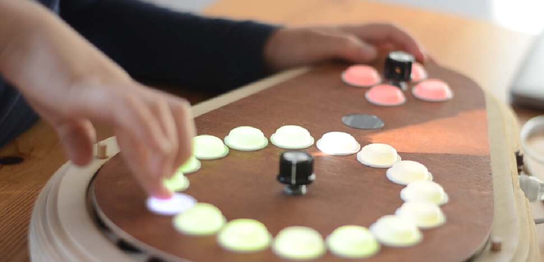
Final project Initial conception (Febuary 2022) Learning to play any musical instrument takes a very long time and a lot of effort. To enjoy music …
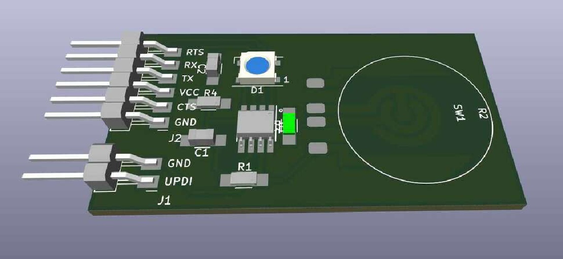
For Electronics Design I finally have the chance to start working on my final project. For this week we need to design a “Hello World” PCB with a micro-controller, one button and one LED. As my final project is going to need a lot of buttons, this is a good chance to start the design of a single button and have the chance to test it.
My final project is going to consist of a keyboard with 24 buttons for the right hand, four buttons for the left hand and a rotary encoder. The buttons should be:
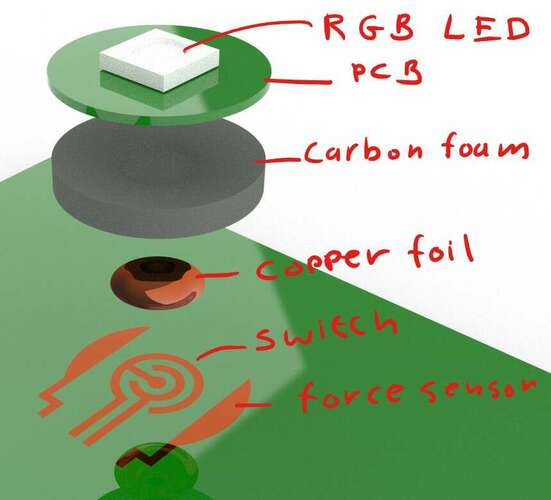
The requirement to be able to emit light makes it impossible to use capacitive sensors. To achieve both a switch and a pressure sensor, the switch circuit should not be an existing button but rather be part of the PCB design.
 |
|---|
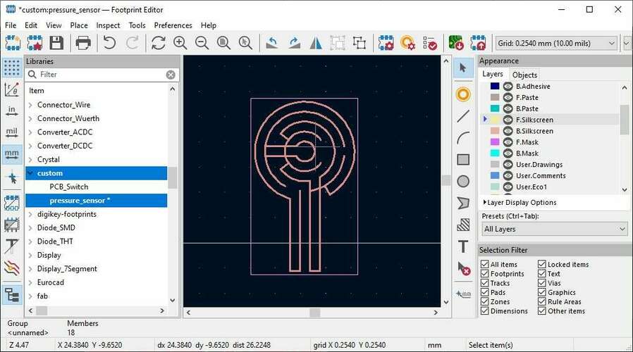
| Eventually the switch will be part of the pressure sensor. |
To have a switch like this I would need to make my own PCB footprint in KiCAD.
My HelloSwitch board will need the following components:
| Part | Purpose |
|---|---|
| ATTiny412 Micro-controller | Read the switch, control the LED |
| WS2812b RGB LED | RGB Light |
| Resistor 10kOhm | Voltage divider for the pressure sensor |
| Capacitor 100nF | Decoupling capacitor for both the ATTiny412 and the WS2812b |
| 2-pin SMD header | For UPDI Programming |
| 6-pin FTDI header | For serial communication |
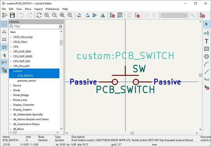
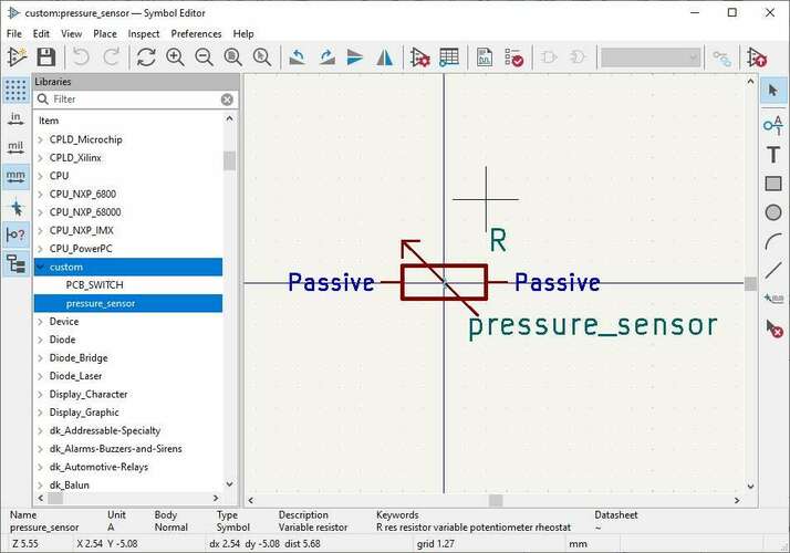
To have the switch and the pressure sensor on the board I have to make custom parts in KiCAD. A part consists of a symbol and a footprint. Symbols can be drawn in any shape but must have pins defined that match with the pins on the footprint.
 |
 |
|---|---|
| The switch is going to be a classic “normally open” switch, so I decided to “borrow” and edit the symbol from the “fab” parts library. | The sensor is essentially a variable resistor, so this symbol is also “borrowed” from the kiCAD libraries itself |
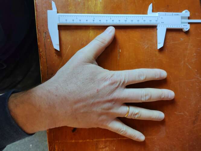
For the footprints I needed to estimate the eventual size these buttons are going to have. To determine the size of the footprints I photographed and measured my own hand to see what size of keyboard would be comfortable to play.
 |
 |
|---|---|
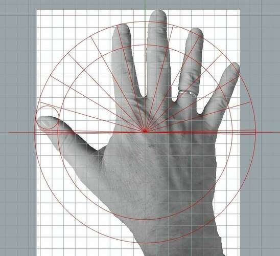
| Original image of my own hand being measured. | In Rhino I Estimated the keyboard pattern based on the measurements. |
From the analysis of my own hand I determined that a key, if round, would have a diameter of 20mm. I decided to draw the PCB layouts of the sensors in Rhino, so I would have slightly more sophisticated drawing methods at my disposal.
 |
 |
|---|---|
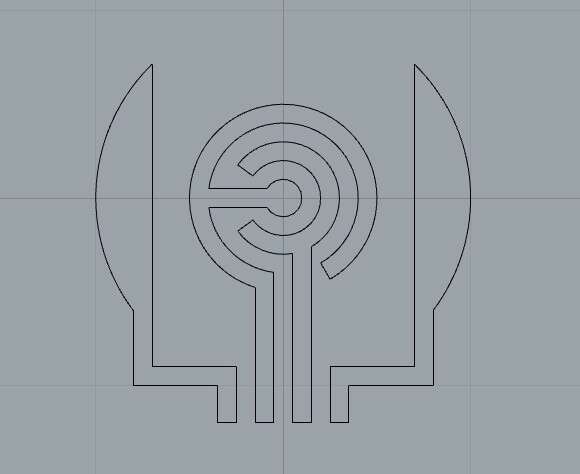
| Both the switch and the sensor drawn in Rhino | The resulting exported vector files couldn’t directly be imported in KiCAD because Rhino doesn’t export filled polygons. |
I had to use InkScape to import the polygons, join them with by selecting the nodes and pressing shift-j and then filling them.
Eventually I could use my footprints in my schematic.
 |
 |
|---|---|
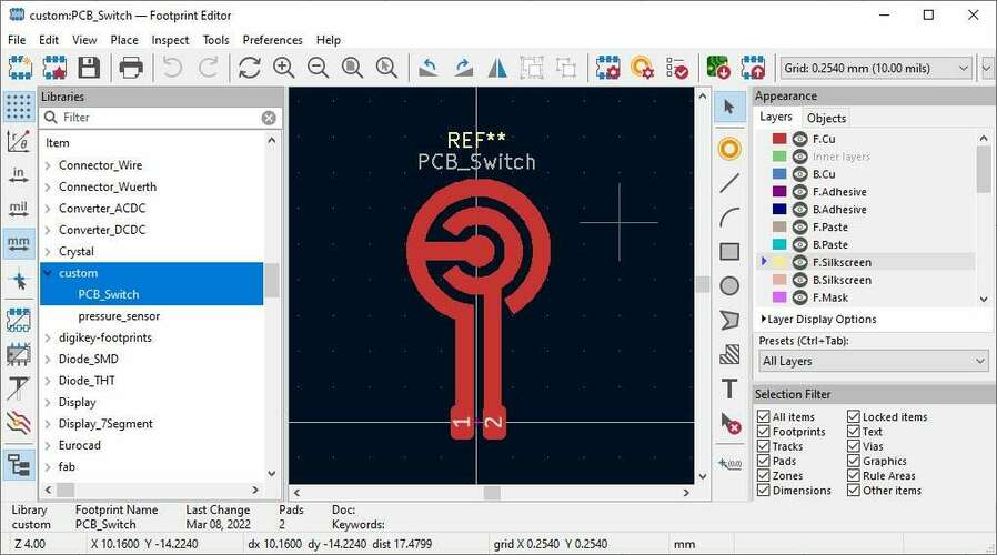
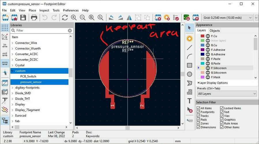
| The siwtch… | …and the sensor as to separate footprints. |
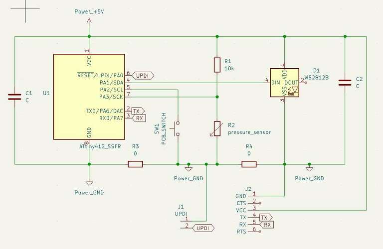
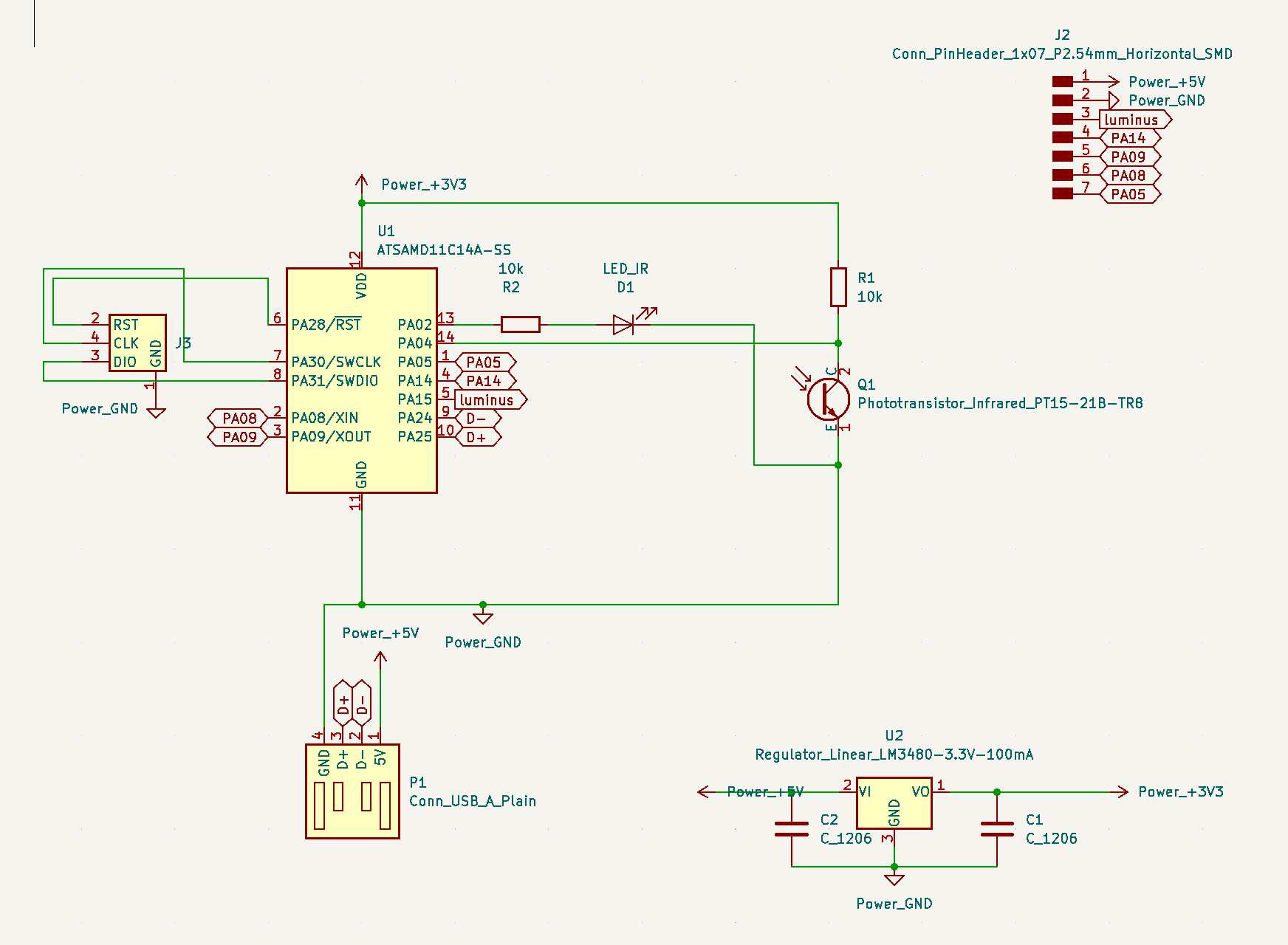
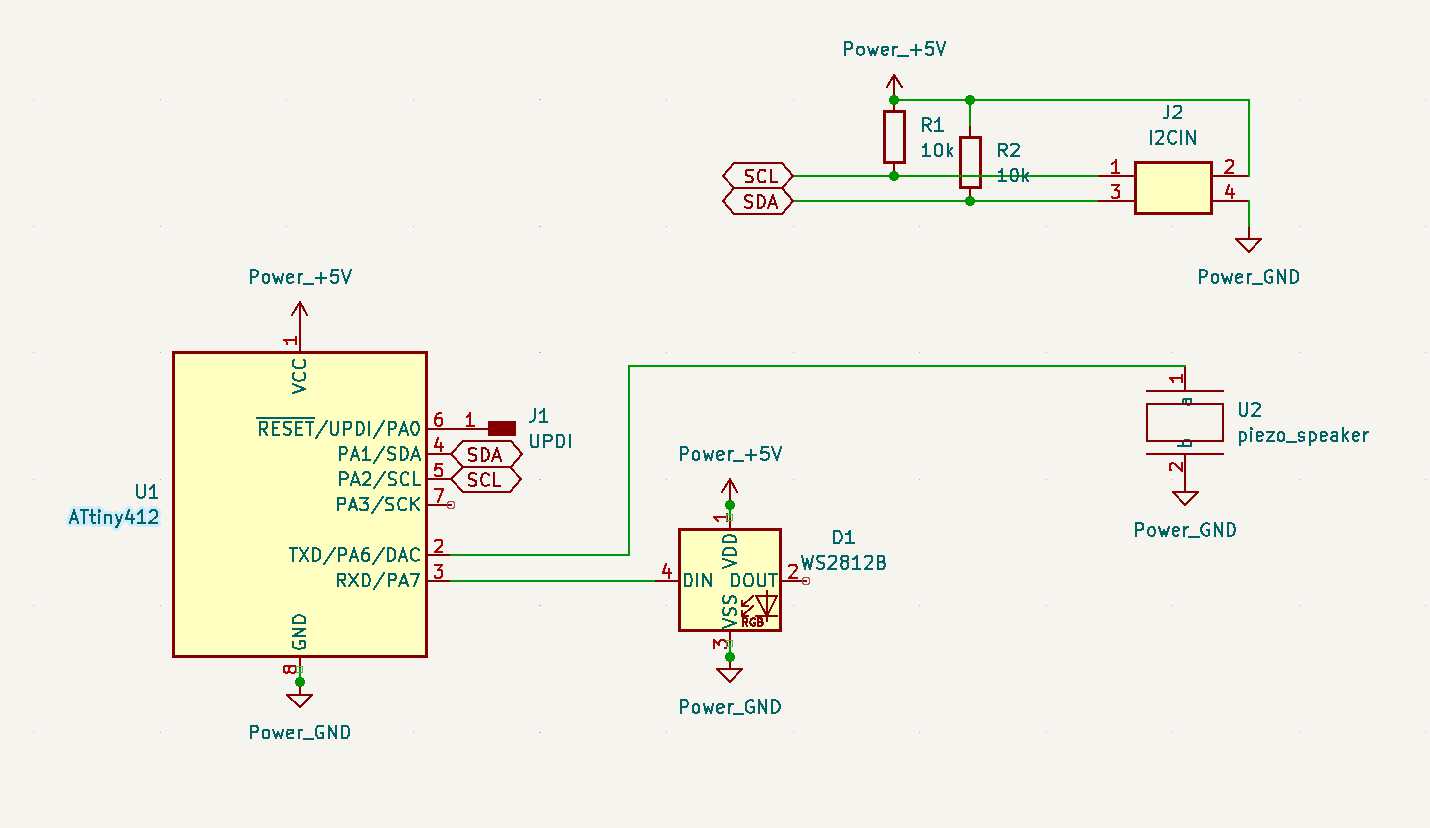
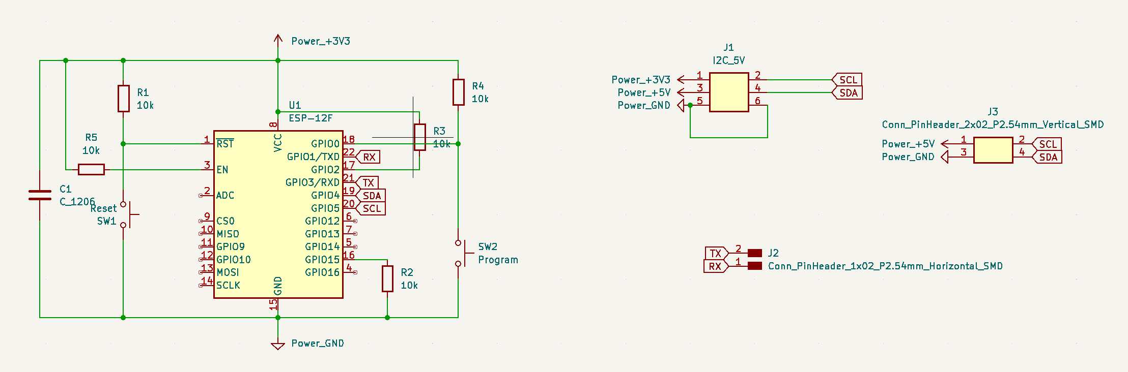
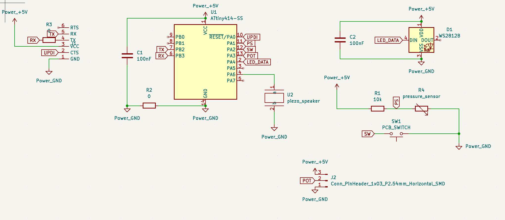
I chose to make the schematic as a whole instead of using a lot of labels.
 |
|---|
| The schematic. Labels are used for the connectors to reduce clutter. |
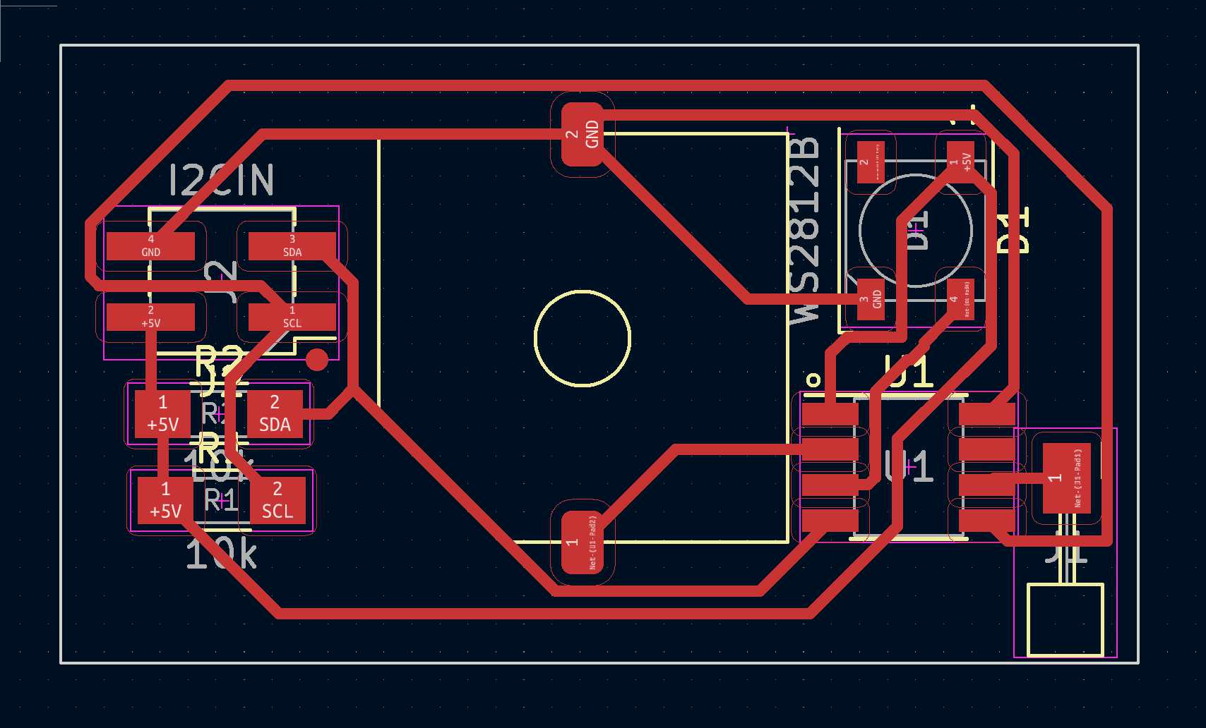
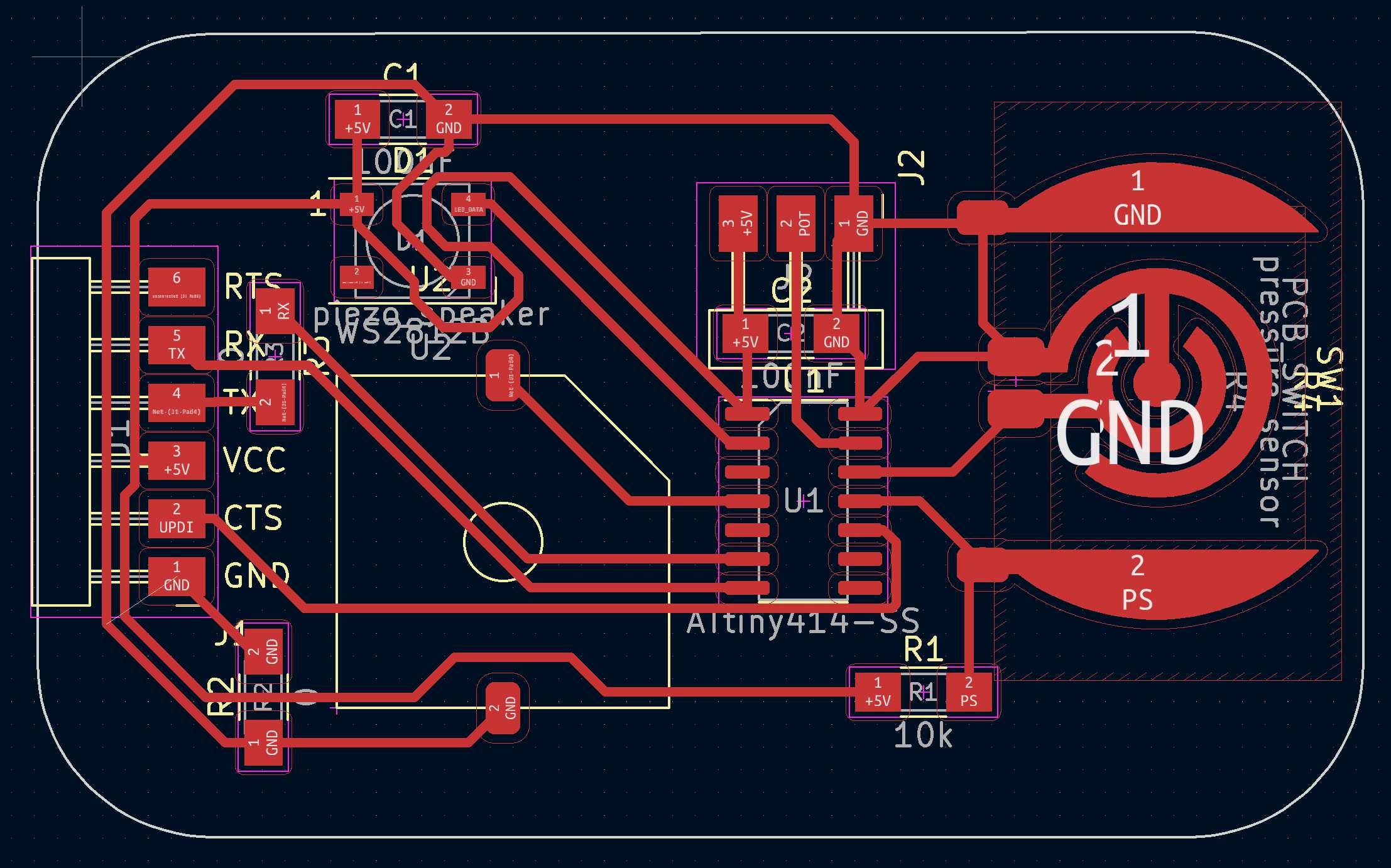
The PCB could then be created. A ground-plane fills all the empty spaces.
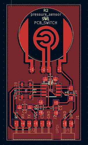 |
|---|
| While drawing the PCB I found I needed some 0Ohm resistors to be able to have all the GND pins connected. |
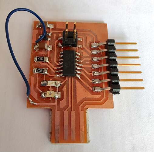
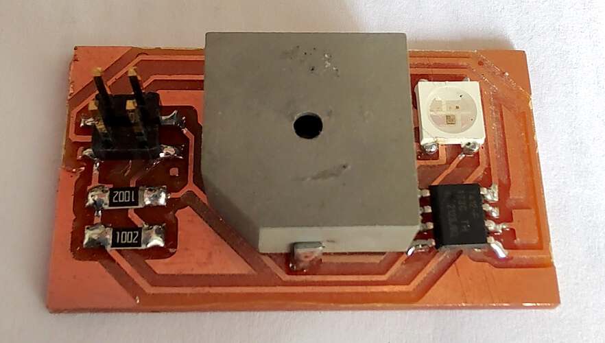
The PCB was eventually milled and it worked, as can be seen in the documentation for Embedded Programming and Input.
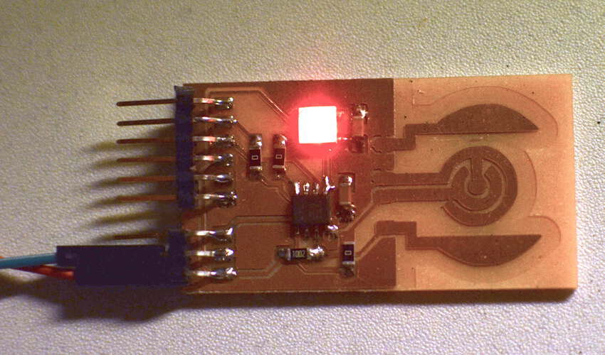 |
|---|
| The PCB worked. I could control the RGB LED and the analog input returned significantly different values when a piece of carbon foam was pressed to it. |
Here’s an overview of all the PCBs I designed and made during the entire cycle. The design files can be found here.
This board got made for the machine week. Eventually we chose to go for another solution.
 |
 |
 |
|---|---|---|
| Schematic | PCB | Result |
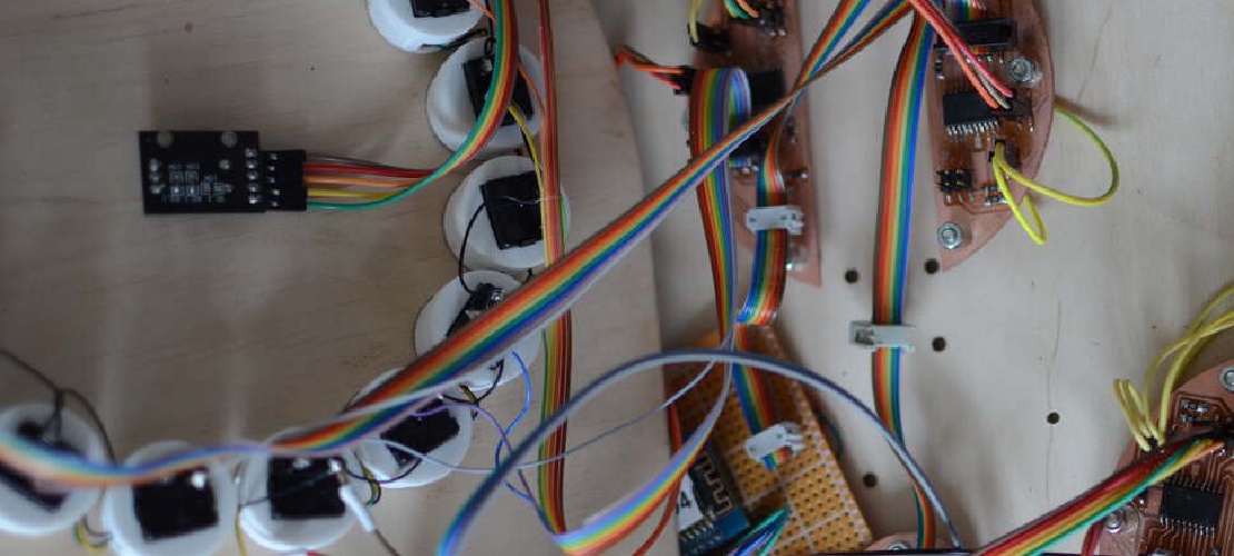
This board got made for the Networking and Communications assignment. It tought me the method of connecting devices on a bus using ribbon cables.
 |
 |
 |
|---|---|---|
| Schematic | PCB | Result |
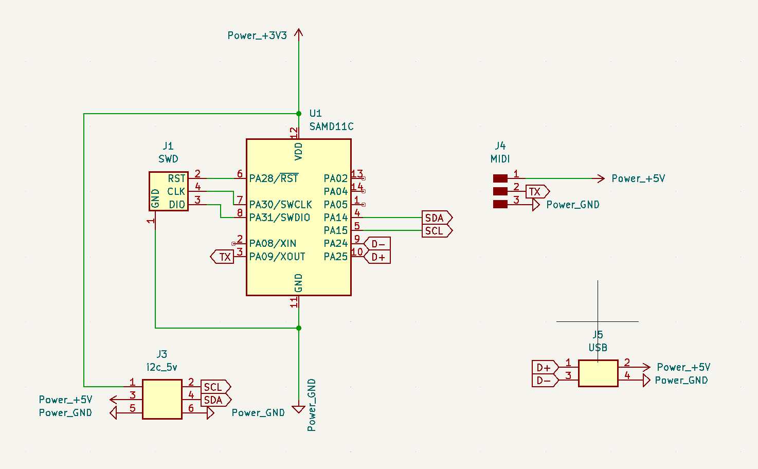
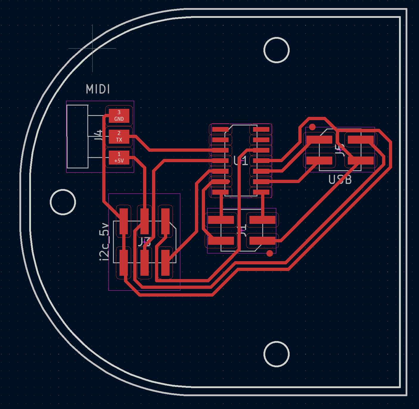
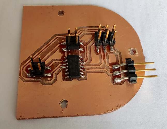
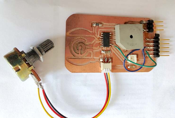
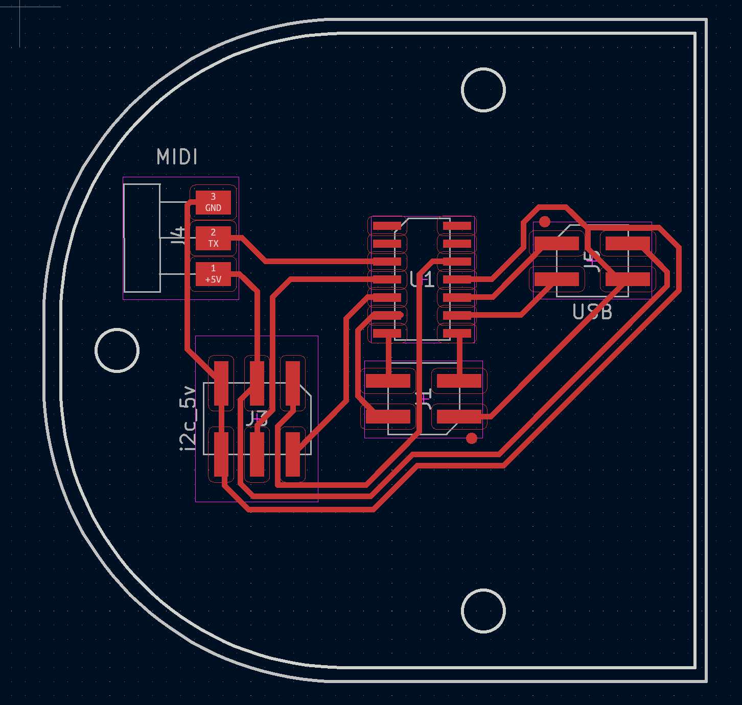
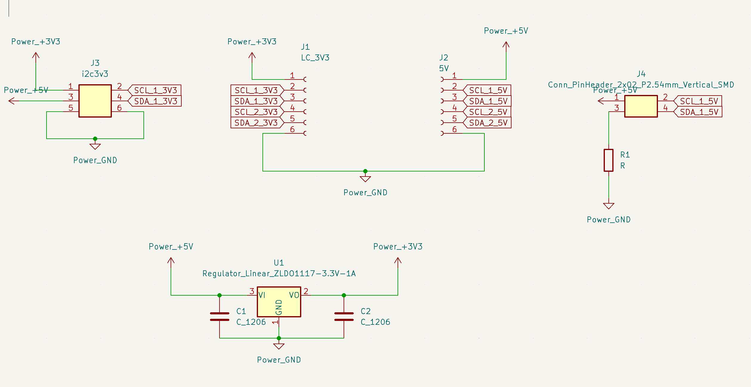
This board converts USB-Midi to serial Midi. It actually works very well but it didn’t make it into the final project as I had difficulties mixing 3.3v and 5v devices on the same i2c bus.
 |
 |
 |
|---|---|---|
| Schematic | PCB | Result |
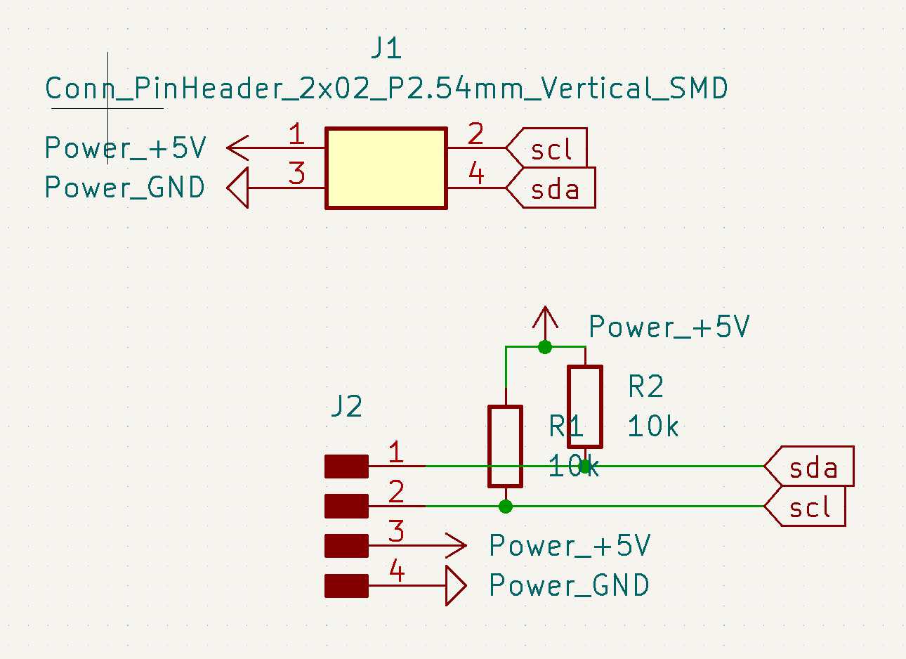
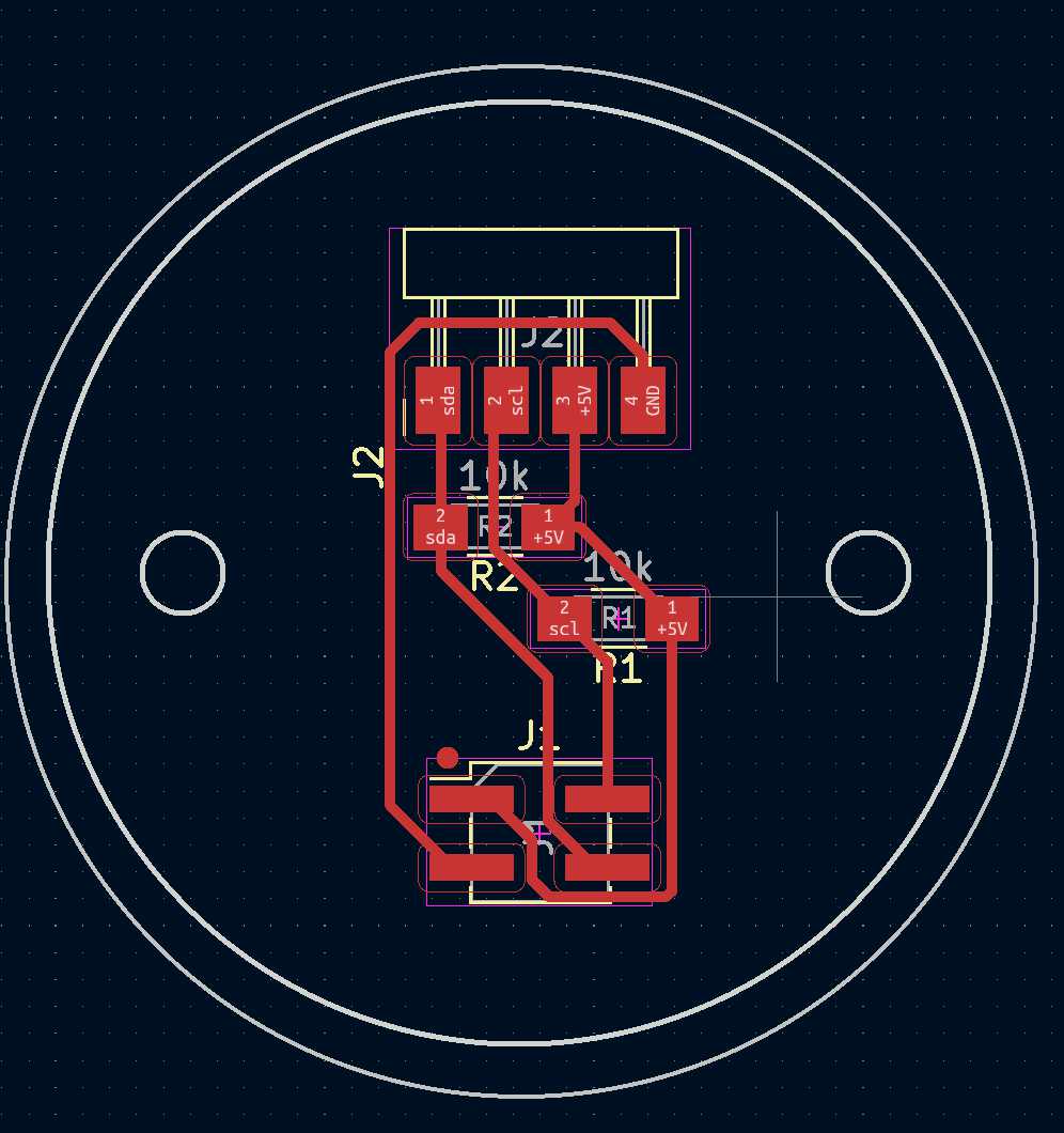
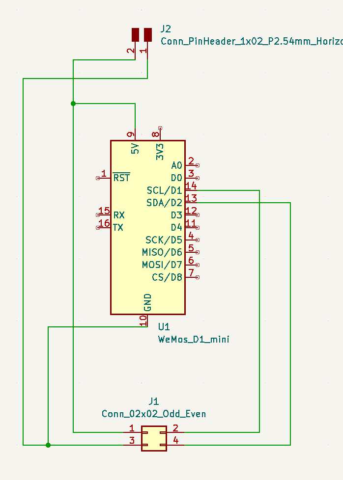
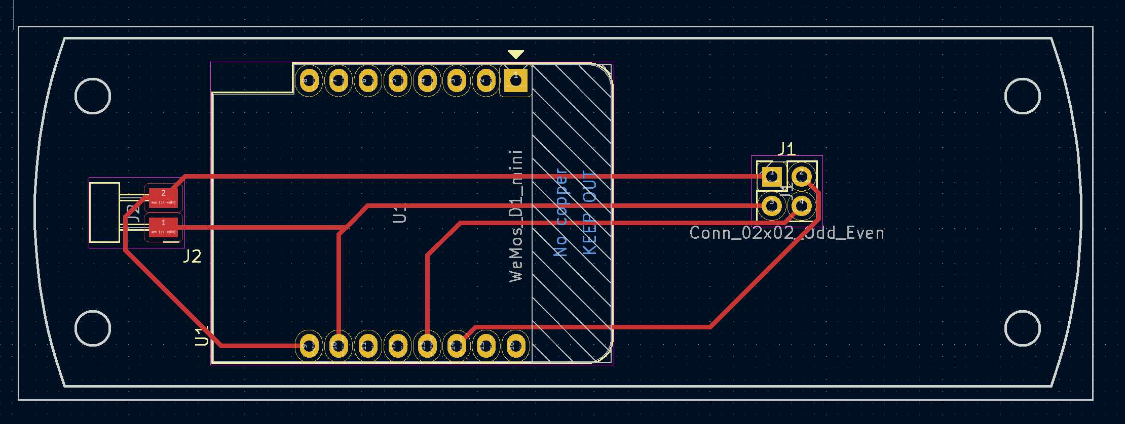
This board served as a connector converter to make the OLED display compatible with the I2C ribbon cable.
 |
 |
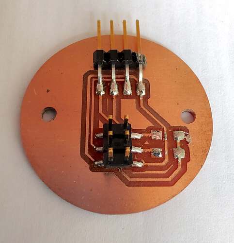 |
|---|---|---|
| Schematic | PCB | Result |
These were variations of boards that would act as the main board for my final project. Unfortunately neither of them made it into the project as I was running out of time. A perfboard solution would have to do.
WEMOS D1 Mini version
 |
 |
|---|---|
| Schematic | PCB |
ESP12f version
 |
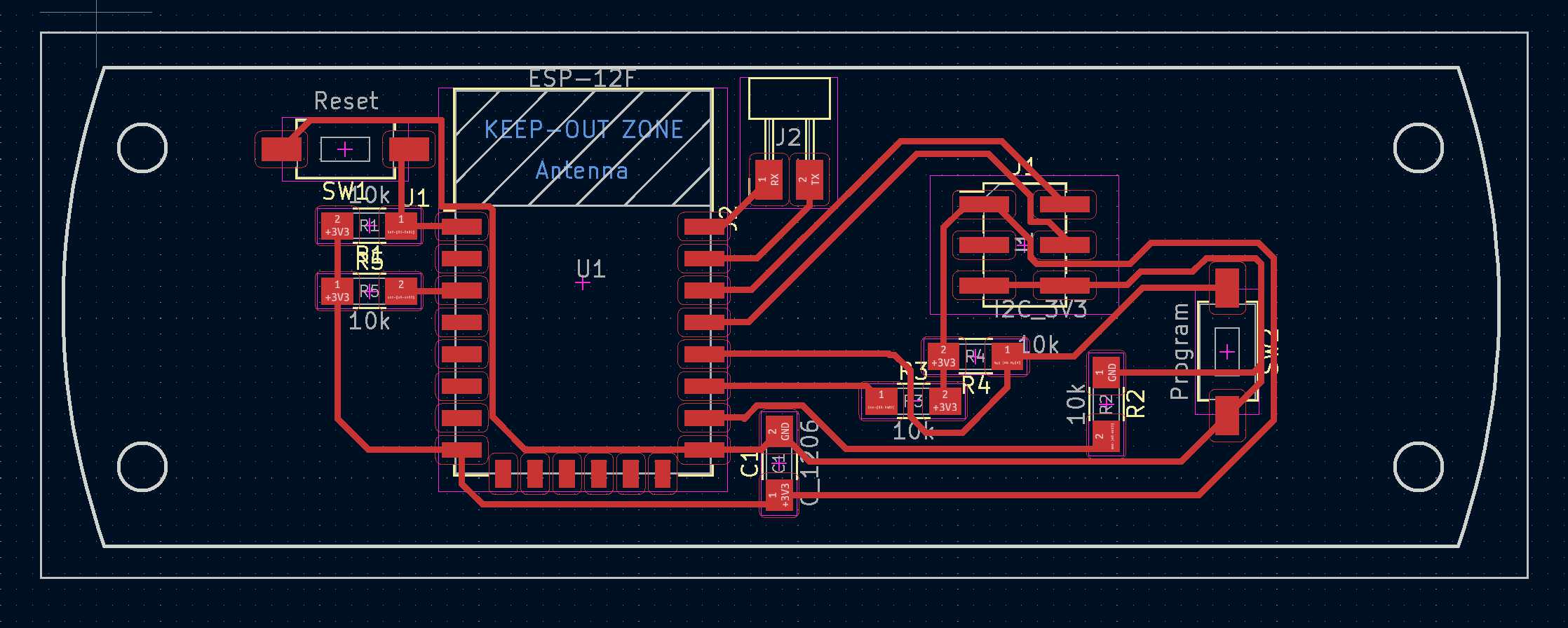 |
|---|---|
| Schematic | PCB |
This board got made during the output devices week. It contaiuns an SMD piezo speaker connected to the DAC of an Attiny416
 |
 |
 |
|---|---|---|
| Schematic | PCB | Result |
I planned to make a small PCB for each button on the Feib instrument. Eventually I saved some time by cutting up an LED strip.
 |
||
|---|---|---|
| Schematic | PCB | Result |
I thought I could mix logic levels on the I2C bus of my final project by using an AdaFruit level converter board. I made this board to convert logic levels and essentially end up with 2 busses. It didn’t work.
 |
 |
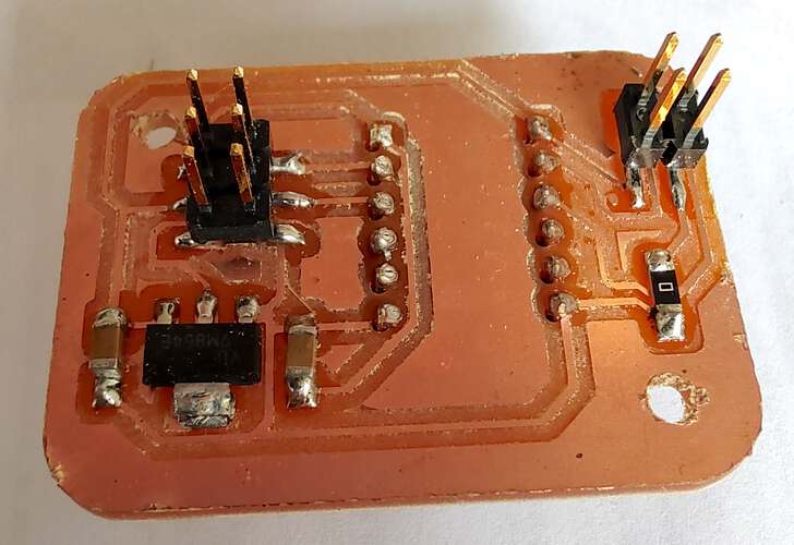 |
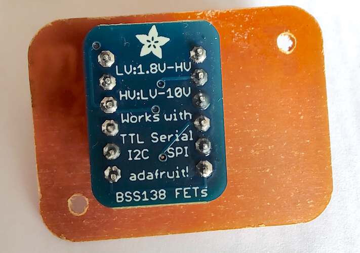 |
|---|---|---|---|
| Schematic | PCB | Top | Bottom |
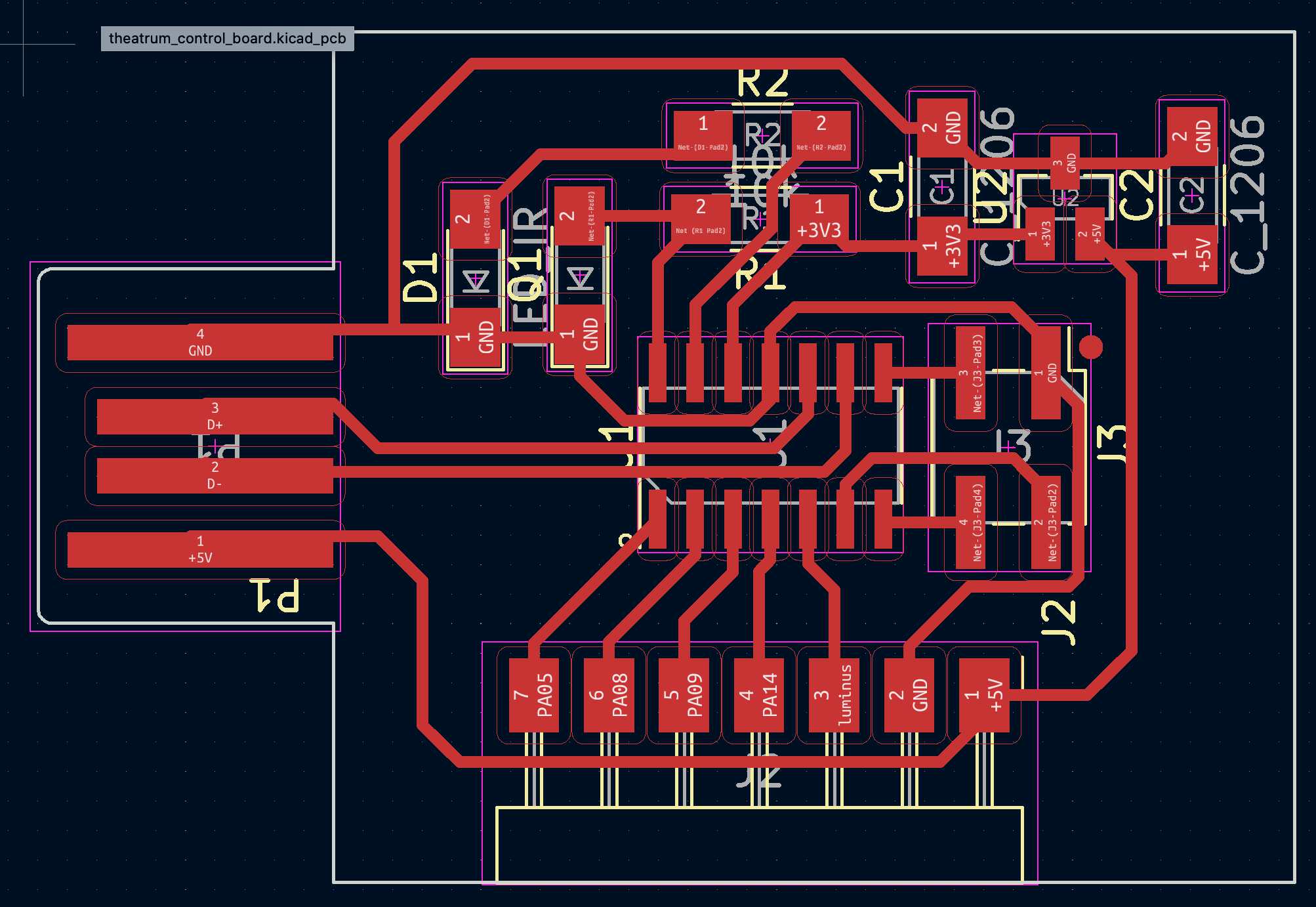
The Theatrum machine needed a very bright LED. Four Luminus LEDs would certainly do. They were controlled using a MOSFET on a nother board.
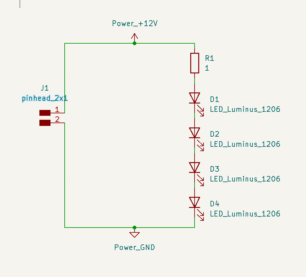 |
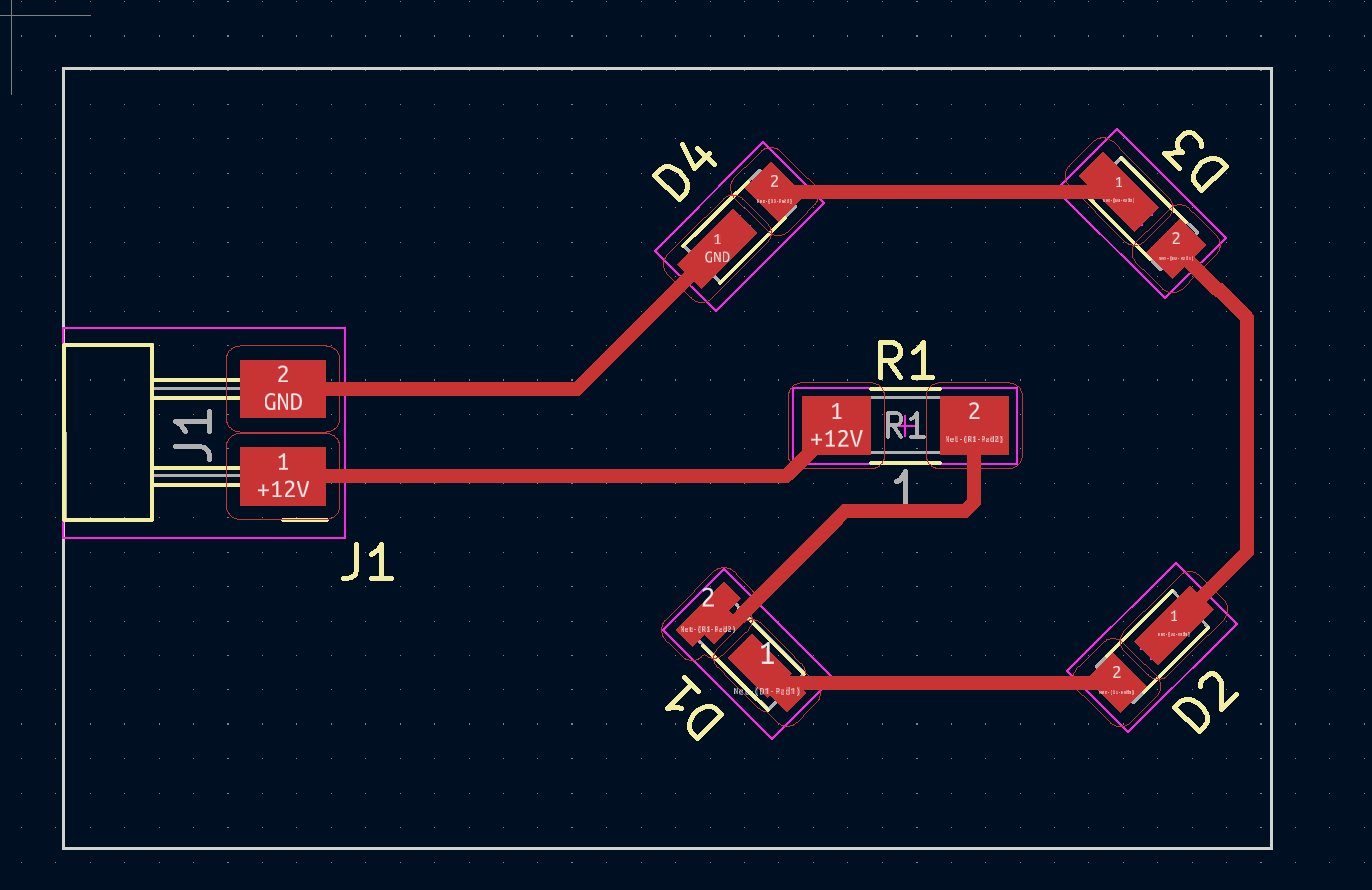 |
|---|---|
| Schematic | PCB |
 |
 |
|---|---|
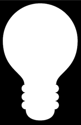
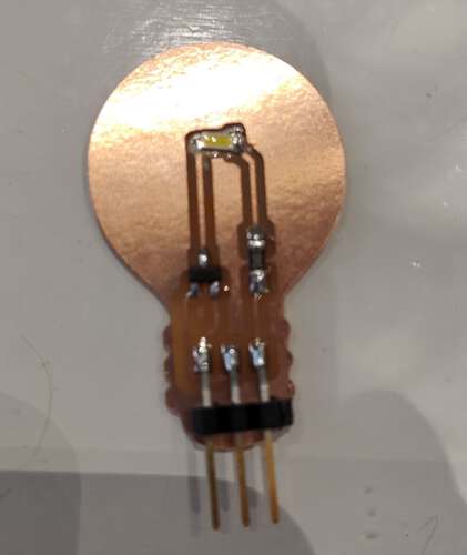
| A silhouette of a lightbulb, found using google image search, served as the outline of the board. | The picture of the resulting PCB is of an earlier version |
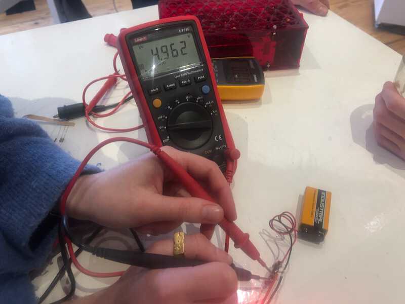
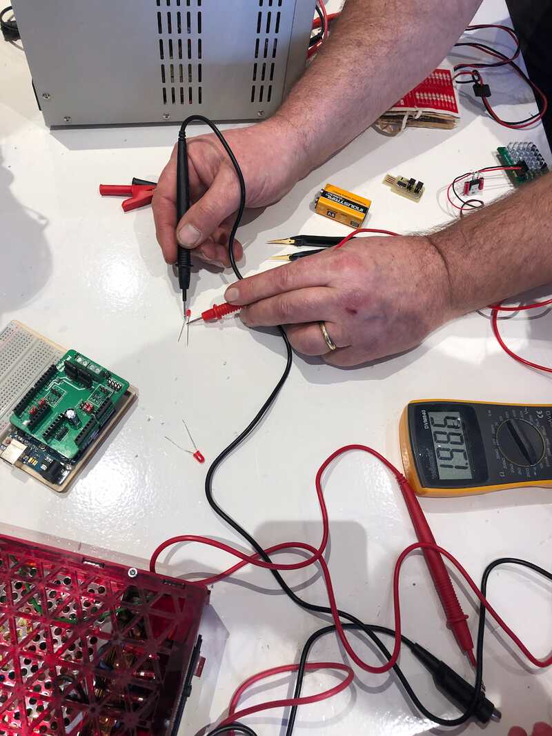
The group tested some electronic components using the measurement equipment available.
 |
|---|
| The multimeter was used to measure voltage. In this case the voltage of a 9v battery. |
 |
 |
|---|---|
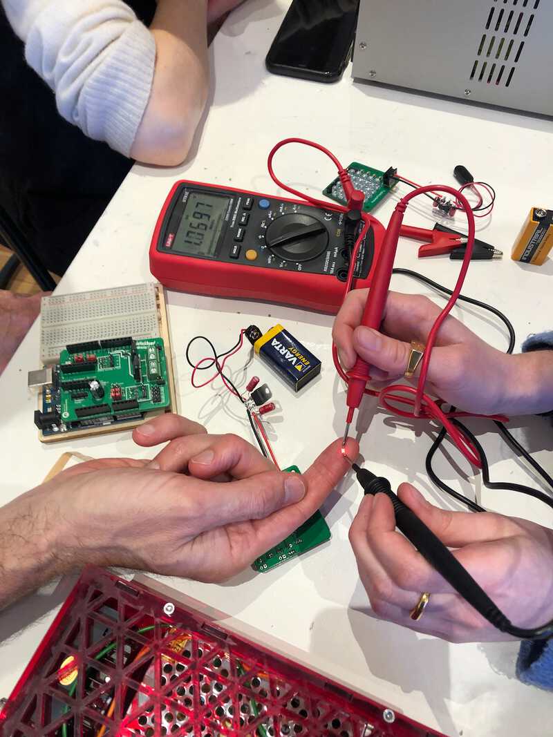
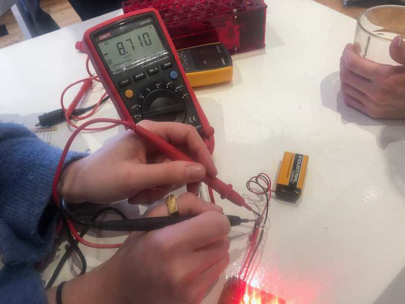
| The most used function of the multimeter is to measure wether current can flow through a conductor. | The diode test can be used as a connectivity test |
 |
|---|
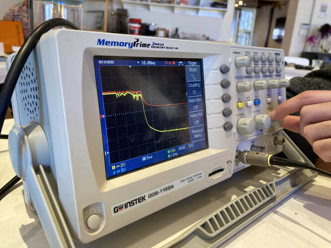
| Alternating voltages over time other than very slowly changing voltages can’t be measured using a multimeter. Here we try to measure the voltage drop over time of a capacitor. There’s certainly a change but we can’t see how the capacitor discharges over time. |
 |
|---|
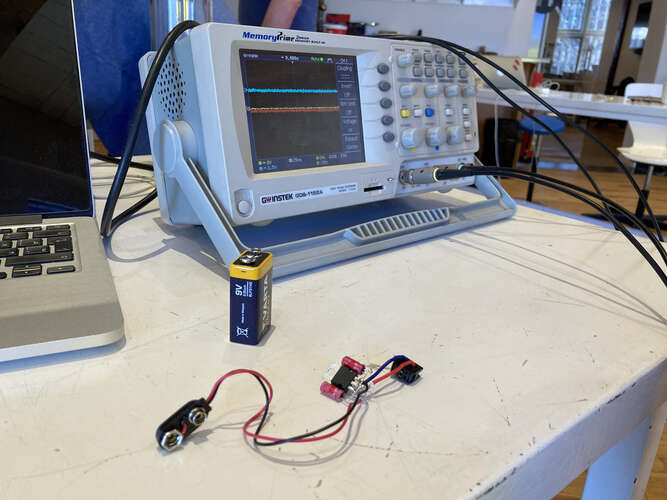
| To measure changing voltages over time we used the oscilloscope. |
 |
 |
|---|---|
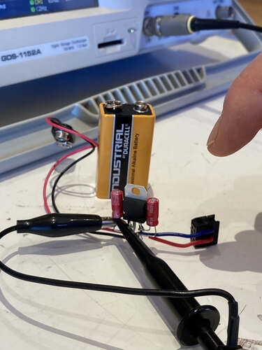
| By measuring the voltage between the positive and the negative side of an electrolytic 100nF capacitor… | …the oscilloscope shows us the change of voltage over time when the capacitor is discharging. |
 |
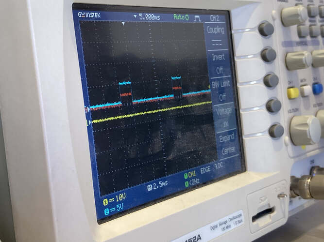 |
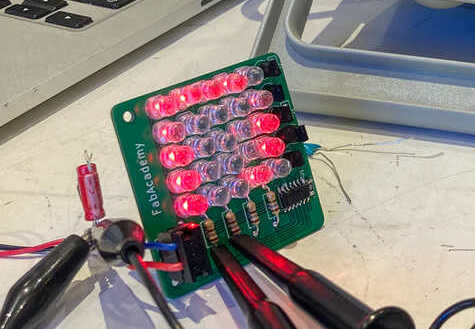
|---|---|
| A microcontroller generates changing voltages over time, in this case to switch LEDs on and off very fast. | These signals can be nicely visualized as block-waves on an oscilloscope. |
Final project Initial conception (Febuary 2022) Learning to play any musical instrument takes a very long time and a lot of effort. To enjoy music …
What I did. I created the enclosure and designed and milled all the PCBs. TODO Hardware Priority 1 20 x Button LED caps 8x Octave1 8x Octave2 4x chord …