Final Project
Final project Initial conception (Febuary 2022) Learning to play any musical instrument takes a very long time and a lot of effort. To enjoy music …
My final project will have three types of input:
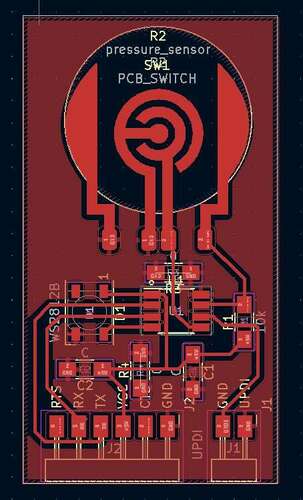
Some of the following input devices were first tested using a special “test board” based on an Attiny412.
 |
 |
|---|---|
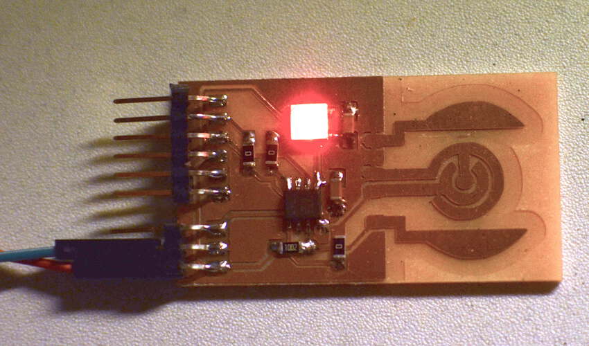
| The PCB design of the test board. | It worked. |
 |
|---|
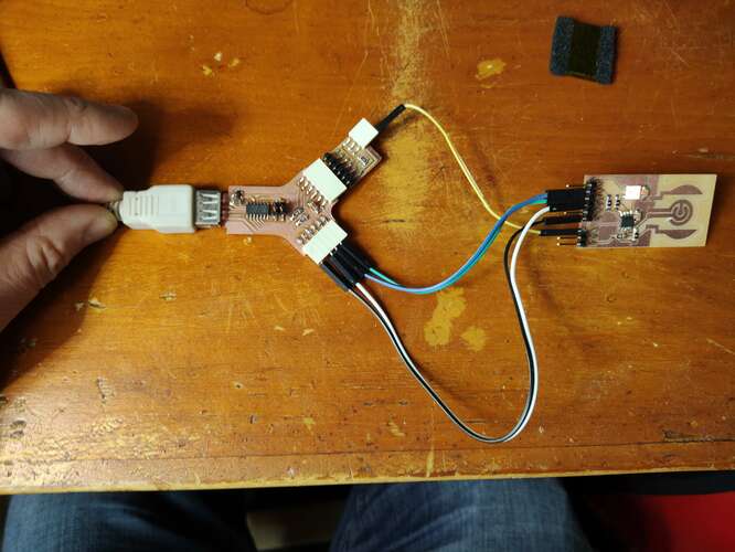
| I could quite easily program and test the device using the dual serial board adapter |
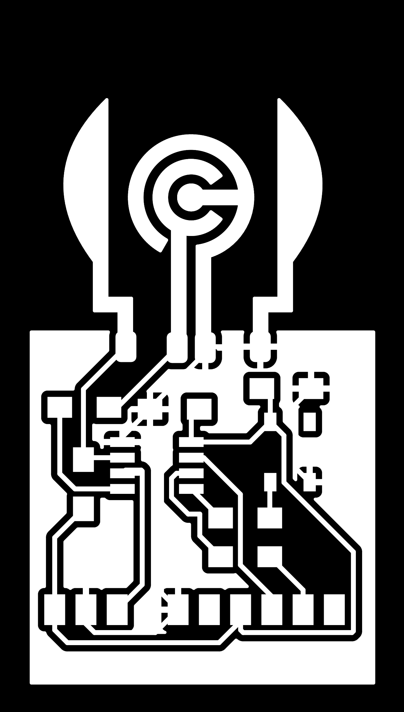
For the first iteration of the “feib” instrument I thought of making my own switches entirely from scratch by making a piece of metal touch two separated copper traces on my PCB.
 |
|---|
| Part of the switch is made up of two copper traces on the PCB that are made to be touched by another piece of copper foil |
| By touching two copper traces with a piece of aluminum foil, a button press can be registered. |
To make my own buttons would also involve designing and creating my own springs. That proved too much work so I opted for another solution.
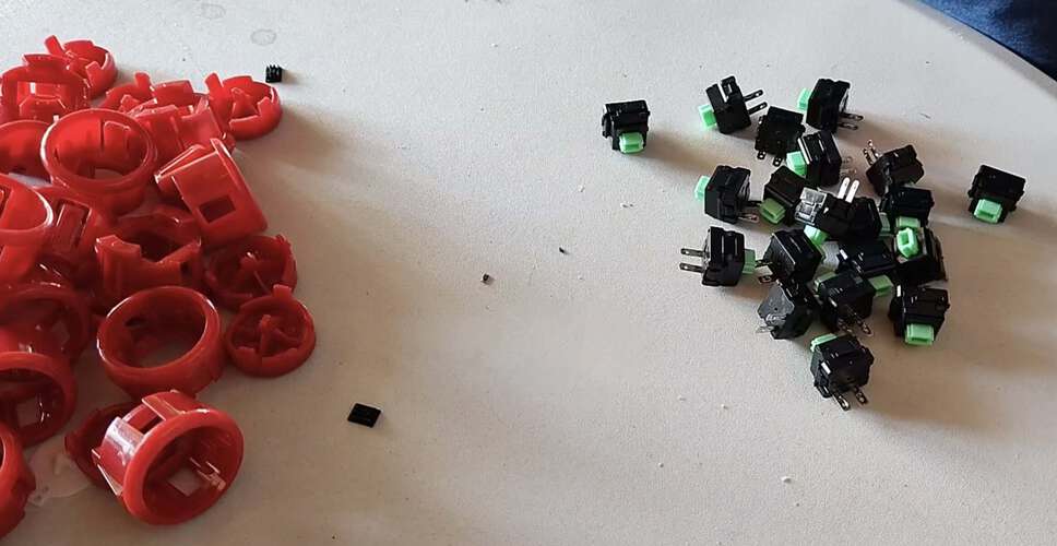
Eventually, the buttons I used were nothing special in terms of input. I used the switch-part of commercially available arcade buttons. T
 |
|---|
| The switches from arcade buttons were repurposed |
o prevent me from having to use resistors I used the internal pull-up resistor of the Attiny3216 microcontroller I used.All buttons were initialized using the following code:
for (uint8_t iButtonPin=0; iButtonPin<NBUTTONS; iButtonPin++)
    pinMode(iButtonPin, INPUT_PULLUP);
As the state of the buttons was only sampled for 100 times per second, I didn’t need debouncing, as button bounce occurs of much shorter time frames.
All eight button states could be stored as separate bits in one byte making it quite easy to perform edge detection for all eight buttons at once using binary operations:
void update(){
    lastPollButtonStates = inputState.buttons;

    // get current button state here
    // ....

    buttonsFallingEdge = ~inputState.buttons & lastPollButtonStates;
    buttonsRisingEdge = ~lastPollButtonStates & inputState.buttons;
}

// Functions below are there to get state of individual
// bits in the bytes representing the state of all 8 buttons
bool getButtonDown(uint8_t buttonIndex)
{
    return (inputState.buttons & (1 << buttonOrder[buttonIndex]));
}

bool getButtonPressed(uint8_t buttonIndex)
{
    return buttonsRisingEdge & (1 << buttonOrder[buttonIndex]);
}

bool getButtonReleased(uint8_t buttonIndex)
{
    return buttonsFallingEdge & (1 << buttonOrder[buttonIndex]);
}
A rotary encoder is just a bunch of switched, turning on and off when a spindle is turned. The order in which the switches are activated determine the direction into which the spindle is turned.
 |
|---|
| The rotary encoder to select the chord progression |
I used a rotary encoder library by Matthias Hertel. I had to adapt the example files a bit because these included defines specifically for the Arduino Uno while I was using an Attiny3216. For each “click” of the encoder, the encoder library code returned an increment of two, so this could be divided by two to get the actual position.
To use the encoder to select from a limited number of menu items I simply used the modulo operator:
chordIndex = (keyboard->chordKeys->inputState.knobPosition % 10);
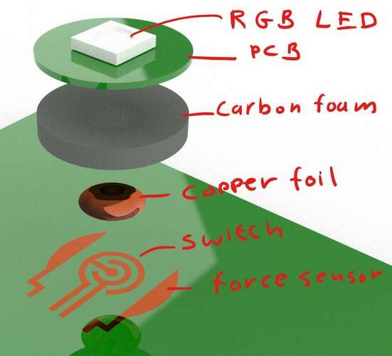
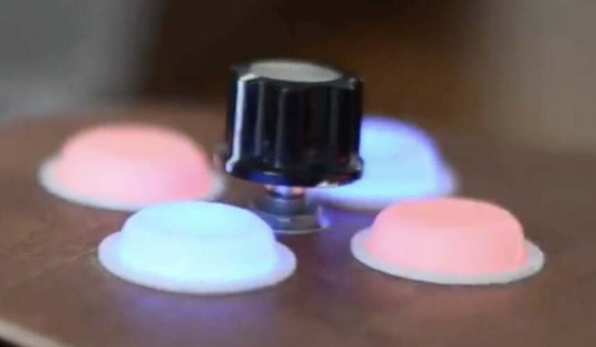
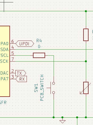
To enable aftertouch I used the conductive properties of carbon foam, inspired by an instructable the I’ve seen years ago. The carbon foam that is used to ship integrated circuits is slightly conductive. It gets more conductive when the material is more compressed. Putting a piece of carbon foam in a voltage divider circuit will and connecting the output to an analog input pin, a very simple and cheap pressure sensor is made.
 |
|---|
| The carbon foam was placed as a resistor in a voltage divider |
| Compressing the foam will yield changes in the signal that are large enough to use as a force sensor |
I was not interested in exact Newtons, Pascals or any other measure. Even non-linearity an hysteresis wouldn’t bother me, as the force readings would eventually be converted into a number used in the midi protocol, ranging from 0 to 128. Accuracy was not an issue.
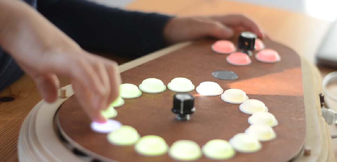
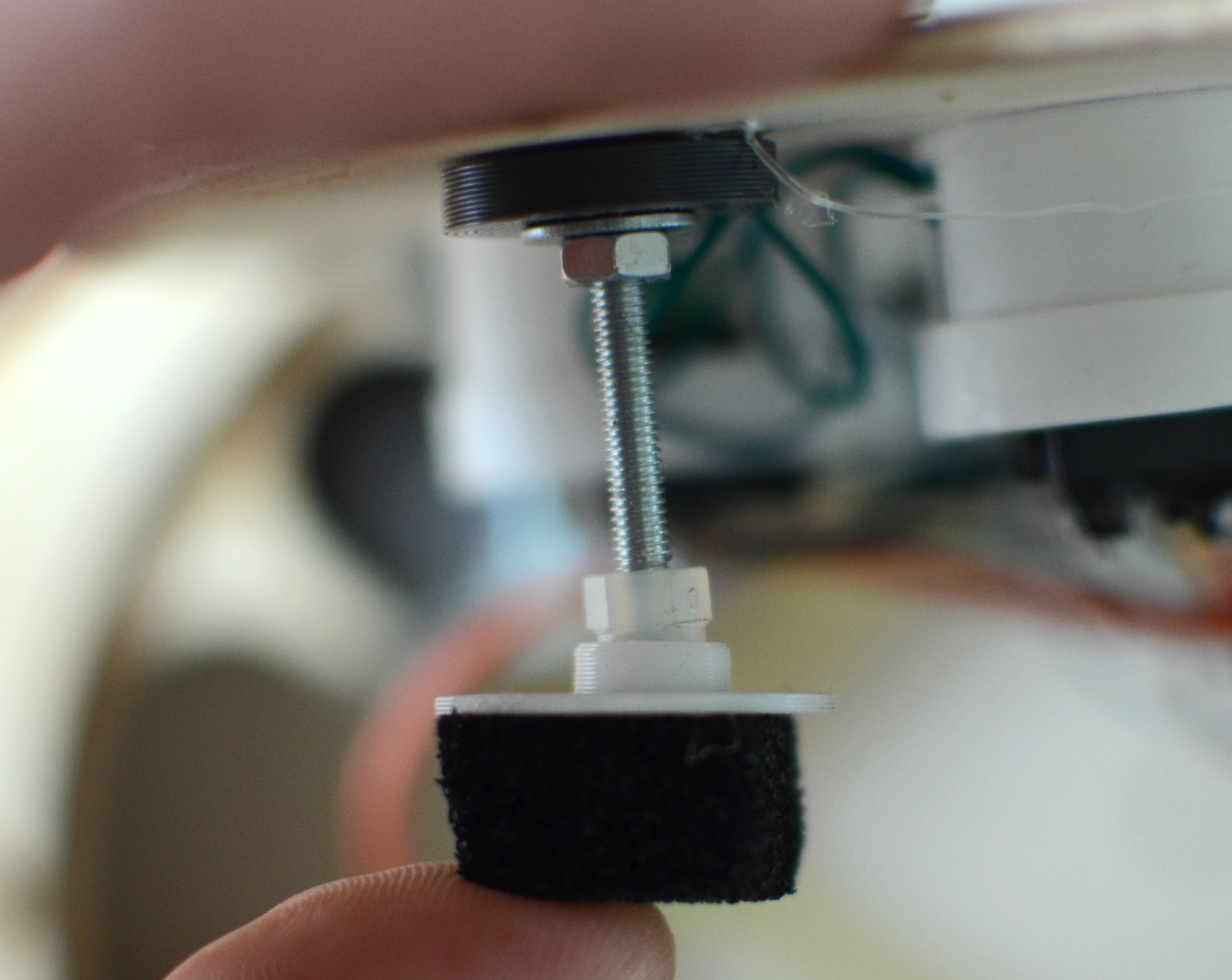
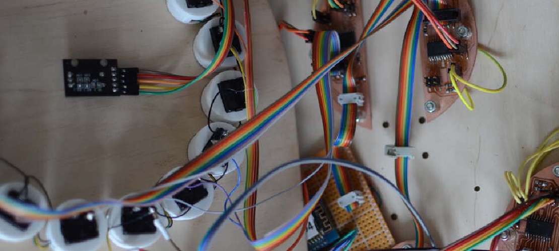
When making the instrument I opted out from making every key force sensitive. By making the lid of the device rest on four pieces of foam I was able to read the pressure in four corners of the device.
 |
 |
|---|---|
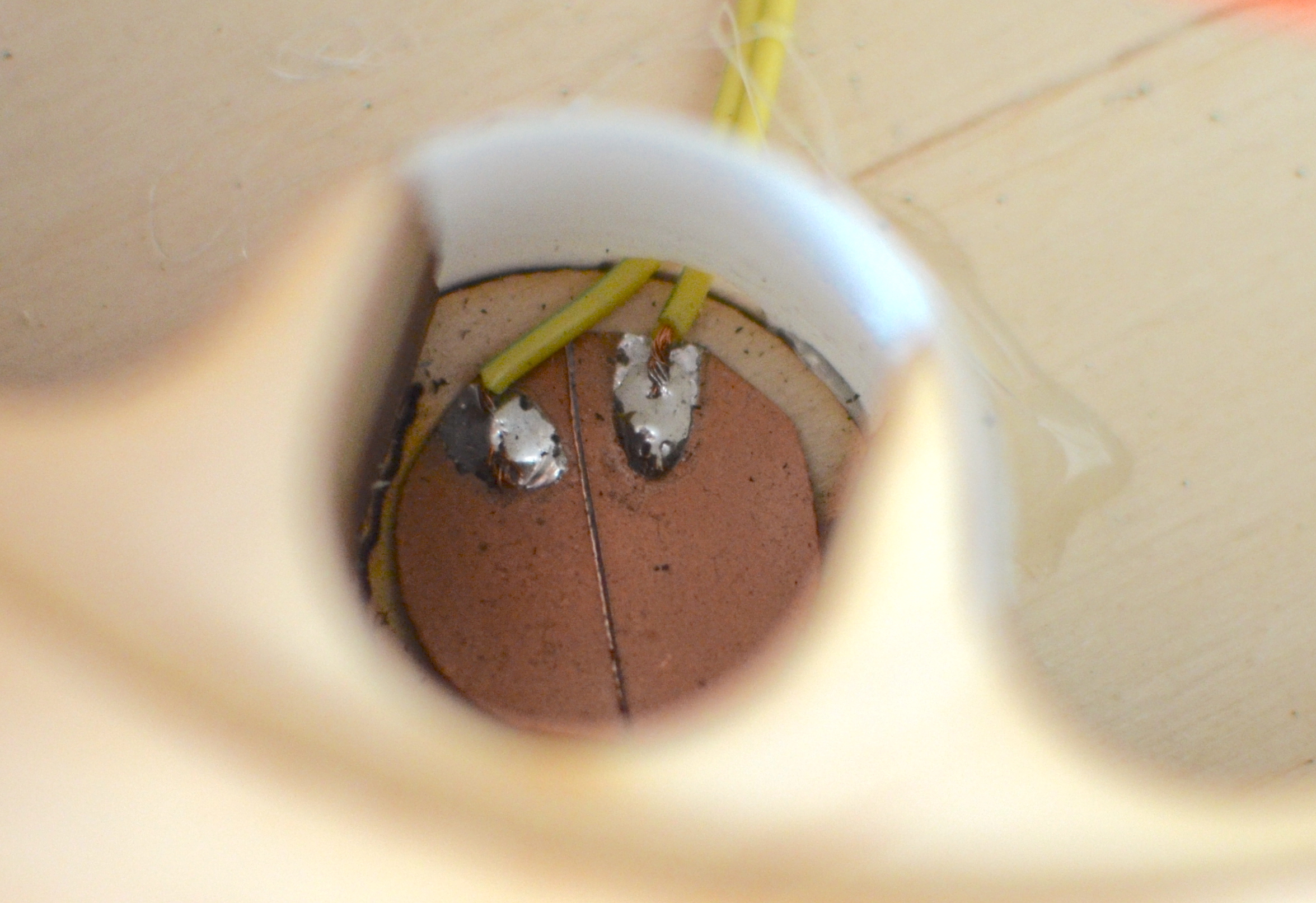
| An M3 bolt with an acorn nut at the end rests on a piece of carbon foam. The acorn nut acted as a ball-in-socket so bolt was able to rotate freely as to make the sensor only register downward pressure. | The carbon foam rests on a piece of copper-clad epoxy (PCB) with two separate pads. |
| Pressing the device at different locations on it’s lid will change the analog signals. |
Unfortunately I wasn’t able to make this work properly as an after touch function due to the limitations of the midi receiver.
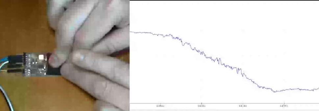
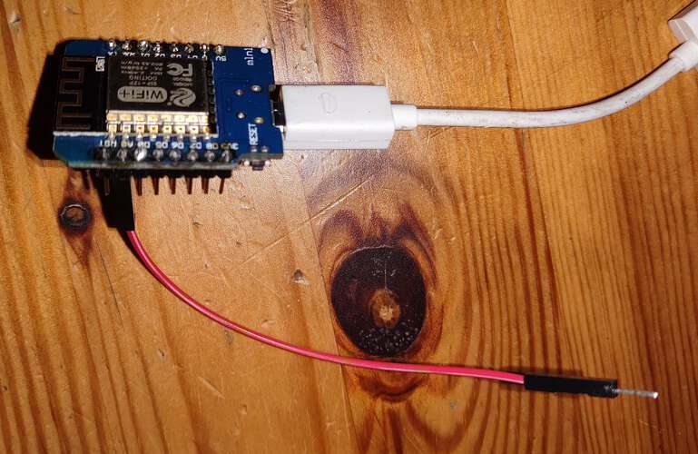
For the group assignment I explored the most basic configuration imaginable for reading analog sensor values. I connected nothing but a single wire to the analog input of my microcontroller. Although this doesn’t sound too eventful, an interesting signal can be measured this way. I chose an ESP8266 based board for this experiment.
 |
|---|
| Only a single wire was attached to the analog input |
The code running on the device was at first:
void setup() {
  Serial.begin(115200);
}

void loop() {
  Serial.println(analogRead(A0));
  delay(1);
}
Using the Serial Plotter function in the Arduino IDE, every ASCII formatted number that is output on the serial port is plotted in a graph. The code above is’t timed very accurately. To be sure the time between samples is roughly the same, the ESP8266 has a nice polled timeout function available
#include <PolledTimeout.h>

void loop() {
  using periodic = esp8266::polledTimeout::periodicMs;
  static periodic nextUpdate(1);

 if (nextUpdate){
  Serial.println(analogRead(A0));
 }
}
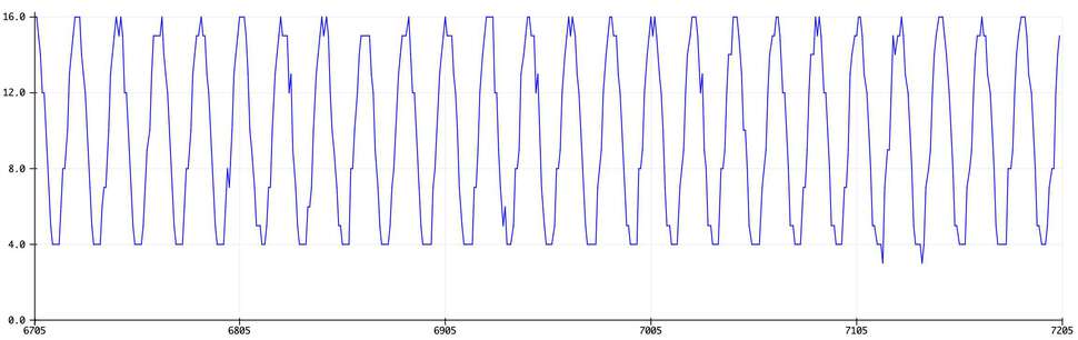
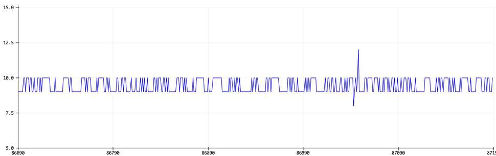
The results could be seen in the serial plotter:
 |
 |
|---|---|
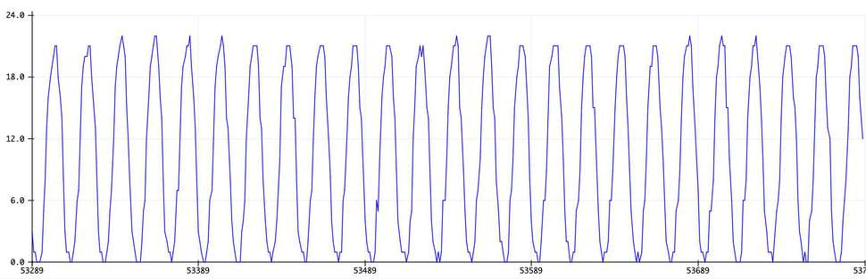
| Measuring with a 5cm long wire attached to the analog input at 1000hz resulted in a sinusoidal pattern | A 15cm long wire resulted in a similar pattern, but with a higher amplitude |
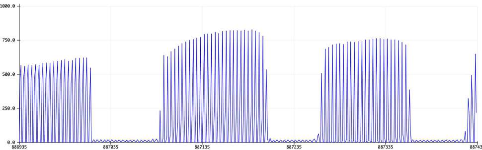 |
 |
|---|---|
| Touching the wire made the amplitude momentarily increase | Disconnecting the laptop from the mains power supply, only letting it run on the battery, almost entirely got rid of the sinusoidal pattern. |
An explanation for the pattern to exist is that the 50Hz alternating current of the mains power supply provides great interference for any analog sensor. A wire will act as an antenna for this noise. The larger the antenna, the larger the amplitude of the noise. Looking at the period, the amount of samples between each repetition of the signal, five peaks can be seen for every 100 samples. Sampled at a 1000hz, 100 samples stands fot one tenth of a second. If five repetitions can be measured in 1/10th of a second, the 50 repetiions can be found in one second = 50hz.
Final project Initial conception (Febuary 2022) Learning to play any musical instrument takes a very long time and a lot of effort. To enjoy music …
What I did. I created the enclosure and designed and milled all the PCBs. TODO Hardware Priority 1 20 x Button LED caps 8x Octave1 8x Octave2 4x chord …