Final Project
Final project Initial conception (Febuary 2022) Learning to play any musical instrument takes a very long time and a lot of effort. To enjoy music …
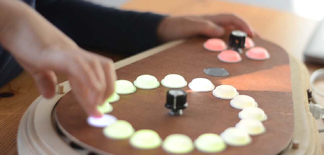
My end project is going to be a keyboard with built-in profiles to easily play music while the keyboard takes care of the music theory. The keyboard will contain:
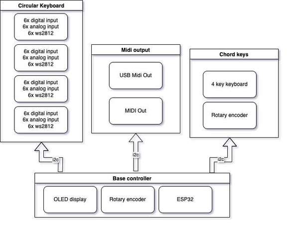
To accomplish all this I need quite a lot of micro controllers.
 |
|---|
| Each of the components above will be controlled by a single microcontroller |
The goal for this week is to determine the microcontrollers I need for each component and test the workflow for each type of microcontroller I want to use.
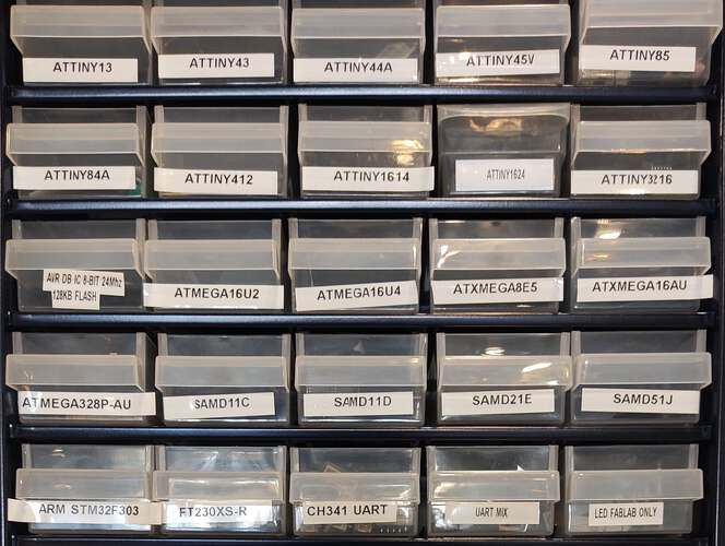
The fablab has multiple microcontrollers at their disposal.
 |
|---|
| These are the microcontrollers I can choose from |
For each component I will choose which microcontroller is best suitable.
The entire keyboard will consist of 24 force sensitive keys. I decided to make the design modular so it will be less complex and I can lower the risk of having broken parts that will break the entire device. Modules can be swapped more easily than en entire main-board.
The keyboard will be divided into four quarters of six notes each. Each quarter of the keyboard mus contain:
| Part | Amount |
|---|---|
| Force sensitive resistor | 6 |
| Digital switch | 6 |
| ws2812 LED | 6 |
| (ad converter) | 1 |
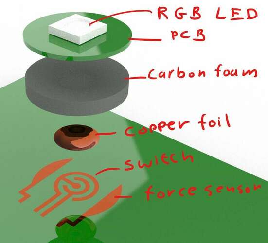
A piece of conductive carbon foam is used as a force sensitive resistor. Carbon foam will be less resistive when compressed, therefore acting as a force sensitive resistor. Two pads on the PCB are used to detect the amount of resistance between them.
 |
|---|
| The switch will be designed as a sandwich of carbon foam and copper |
The resistive foam will start to act as a conductor once it is compressed. This will make the keys act less responsive if the force sensitivity is also used to detect a key-press. The keys should act very responsively, therefore I will have to detect wether a key is pressed as soon as possible. This key-press is detected by a switch that is embedded in the PCB.
The requirements of the microcontroller should be:
| Requirements |
|---|
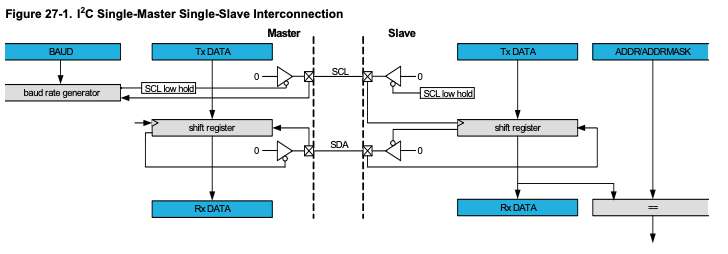
| I2C interface |
| 6 analog inputs |
| 6 digital inputs |
| WS2812 support |
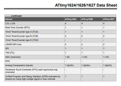
Because a keyboard like this doesn’t require USB or WiFi, my choice would fall onto the attiny family of microcontrollers. These have easily programmable IC2 support and can be easily programmed using UPDI.
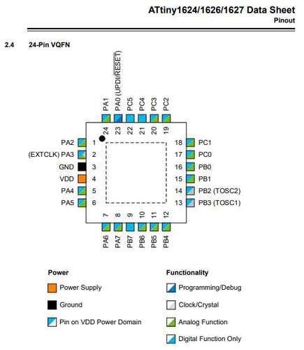
The attiny1624 look well equipped to do the job.
 |
 |
|---|---|
| The attiny1624 supports i2c | 6 analog and 6ndigital pins are readiliy available. Some pins left for i2c, UART debugging, etc. |
To test the attiny1624 I will need a way to program microcontrollers from the attiny series.
MIDI is just a very specific serial protocol. Using buffered outputs and an optocoupler any UART signal can be converted to a MIDI signal. At first I just want to support old-fashioned MIDI. But having USB capable microcontrollers at our disposal opens up the possibility to create a UART to MIDI-USB converter and also support USB midi. This would be very nice, as it would be possible to make my instrument available for all midi applications that run on major platforms, such as VCV rack and raspberry-pi based software synthesizers.
A mictrocontroller for this job would need:
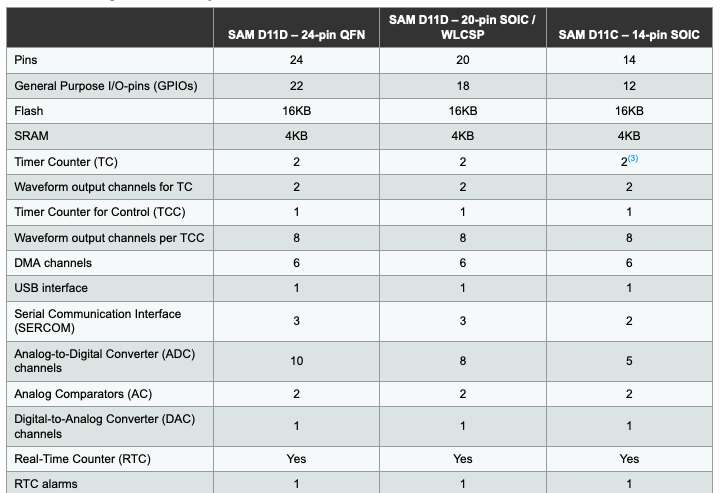
I2C and UART are supported by almost all microcontrollers but USB needs a powerful device. The SAMD11 seems like the device I need to create a I2C-2-UART-2-MIDIUSB converter.
 |
 |
|---|---|
| The SAMD11 supprts USB… | …and I2C |
As a source of inspiration I can refer to a project that was built during the instructors bootcamp by Quinten Bolsee.
The instrument must behave as simple as possible but I would like to make it more configurable using a web-interface. To do this I would need a microcontroller that has a WiFi interface. This microcontroller would also serve as the base board, the controller that is the I2C master and organizes all the data flows through the system.
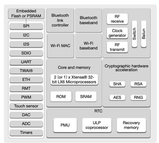
As an extra possibility I would love to have a DAC on this chip so, if time allows it, it could also play its own sounds instead of relying on MIDI instruments.
The ESP8266 had WiFi but the ESP32 is more current, has a separate core for WiFi and some pins support digital audio conversion. ESP32 microcontrolelrs are programmable using a UART interface.
 |
|---|
| The ESP32 has DAC and WiFi |
To test the pipeline of the attiny family and at the same time test the concept behind pressure sensitive buttons, I created a test board in week 6.
I used the Arduino environment to test the programming workflow. To enable the Arduino IDE to upload to attiny family microcontrollers you have to:
To test the force esnistive button I flashed the program FSButtonTester, which is an altered version of a NeoPixel example. I wrote a color interpolation function to interpolate between two colors and I used the analog value I read from the force sensitive carbon foam to interpolate between two colors.
| The color interpolates between red and white, based on the pressure I put oin the carbon foam |
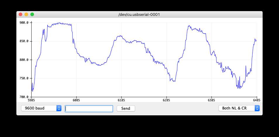
When I serially transmitted the values of the analog port the forcer sensitive pad was attached to I received a satisfactory alternating signal.
 |
|---|
| The pressure on the pad was detected, albeit a bit too sensitive |
To test the button I wrote an Arduino script to change the LED color every time the two pieces of copper on the PCB where shorted.
| The color changes every time a piece of metal shorts the two coper tracks |
Both the button and the pressure-pad work so I’m ready to expand this idea to six buttons on one PCB.
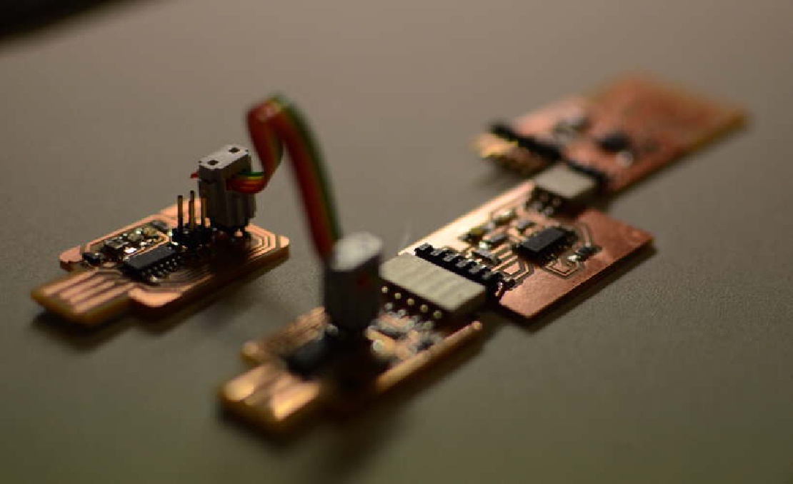
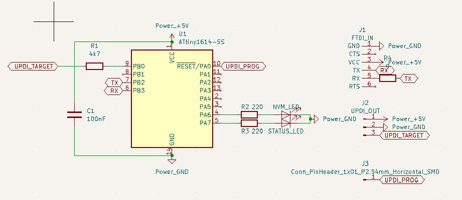
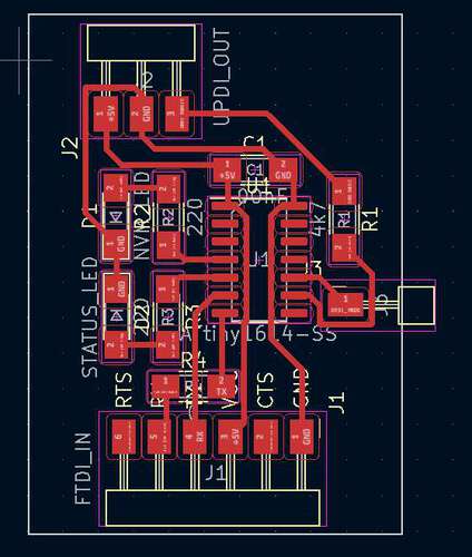
At one point my Serial-to-UPDI programmer setup decided not to work anymore. I resorted to plan B: to use an Arduino to create a jtag2updi programmer. As Arduino’s aren’t allowed as a programmer I decided to make my own jtag2updi board using an attiny1614.
 |
|---|
| The JTAG2UPDI board schematic |
 |
|---|
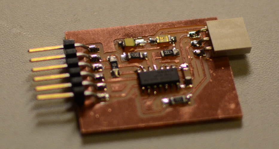
| The JTAG2UPDI board board |
 |
|---|
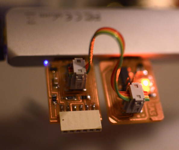
| The JTAG2UPDI board programmer |
The programmer worked, but seemed not to be the source of my problems. The culprit was the SAMD11 based USB to serial converter, which seemed to forget how to operate as such. Probably because the firmware was overwritten. SAtill I’m glad I have a backup method of programming the attiny microcontrollers.
The SAMD11 can be programmed in multiple ways. Using EDBG a SAMD11 microcontroller can be loaded with a bootloader. The bootloader makes it possible to upload new programs without the need for an external programmer.
The process of installing the SAMD11 support in the Arduino environment is rather similar to the attiny412:
I tested the MidiUSB capabilities by uploading a USBMidi demo sketch. I used the SAMD11 USB-to-Serial converter I had made earlier. This board already contained a bootloader. Uploading this program resulted in my SAMD11 completely dissapearing from my known USB devices. I tried reuploading the bootloader using my SWD board. Although edbg stated uploading was successful, the SAMD11 board did not return.
 |
|---|
| Programming the SAMD11 with a SAMD11 using EDBG |
Using EDBG on a mac required a small adjustment and a recompile to the code of EDBG. Fellow student Matti Niinimäki came up with a solution. By adjusting the report_size in the file dbg_mac.c from 512 to 64, edbg could be made to work with a mac.
> ./edbg -b -t samd11 -pv -f sam_ba_Generic_D11C14A_SAMD11C14A.bin
Debugger: Alex Taradov Generic CMSIS-DAP Adapter 0173A589 v0.1 (S)
Clock frequency: 16.0 MHz
Target: SAM D11C14A (Rev B)
Programming.... done.
Verification.... done.
I was successful in making the attiny board work. Unfortunately I didn’t have much success with the SAMD11 so I will keep trying. I ran out of time to test the workflow for the ESP32.
The group assignment and the individual assignment overlapped. I compared three workflows.
All embedded firmware source files I made during this cycle can be found in the folder Embedded Experiments. Eventually I moved some of the more complex projects to PlatformIO. Those projects can be found here.
Final project Initial conception (Febuary 2022) Learning to play any musical instrument takes a very long time and a lot of effort. To enjoy music …
What I did. I created the enclosure and designed and milled all the PCBs. TODO Hardware Priority 1 20 x Button LED caps 8x Octave1 8x Octave2 4x chord …