Project Development.
PROJECT DEVELOPMENT.
Here you can follow my tasks and time management while developing my final project during the month of may. It´s being a challenging task. it´s not the same, when you haven´t got experience, to do weekly assignments following other´s work that to do your own project, starting from 0. I feel like that i´m doing a second fabacademy for my final project, as i´ve got to put on practice nearly everything again, and I love it!
For this assignment, we have to answer the following questions:
- What has been completed, and what tasks remain?
- What has worked, and what hasn´t?
- What questions need to be resolved?
- What will happen when?
- What have you learned?
In order to give the best answers to the questions above, I´ll explain how i´ve planned and developed my final project process, with it´s fails and succesess, questions answered and errors made by task and in cronological order, explaining all testing that i´ve gone through, and indicating which of them were worked during the Fab academy week´s assignments, with their respective links.
As a reminder, all the final files are in the FINAL PROJECT section. You can check them there.
So, here we go:
MATERIAL TESTING:
3D PRINTING FLEXIBLE FILAMENT FOLLOWING METAMATERIAL PRINCIPLES AND TESTS
AIM: To test 3D printing filaments to obtain the adecuate flexibility/pressure resistance, capable of supporting a maximum hand grip pressure in order to combine it with the step response capacitance variation to measure force. To achieve it, I did a lot, but a lot! of testing based on literature´s reviews; Integrating Sensing Capabilities into Mechanical Metamaterial, and Integrating Sensing Capabilities into Mechanical Metamaterial as the main examples.
I tested different types of flexible filament, with different patterns, based on Poisson´s ratio, to obtain the best properties described above. A material capable of being deformed by pressure (but strong enough to resist a maximum grip strenght pressure, about 60kg/cm2), but with flexible capabilties to recover to it´s original shape when no force is applied. I want to explore if I can achieve this goal, as I want it to be, on one side, as reliable and precise as possible, and, on the other side, cheap and sustainable, with the aim of being easily developed in any hospital, or health care center needed.
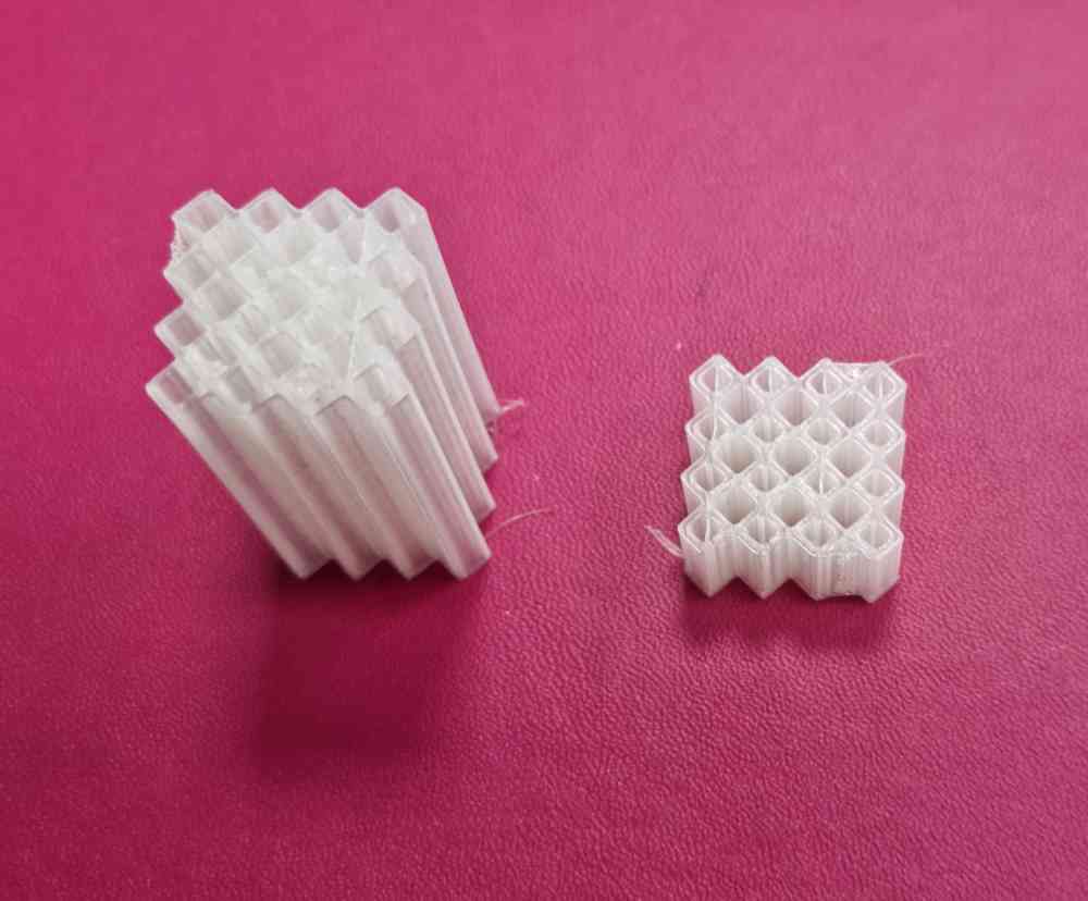
I Made test comparing different types of TPU stiffness (85, 92, 95), and TPE with different patterns (Hexacomb, negative Poisson´s ratio and diamond shape):
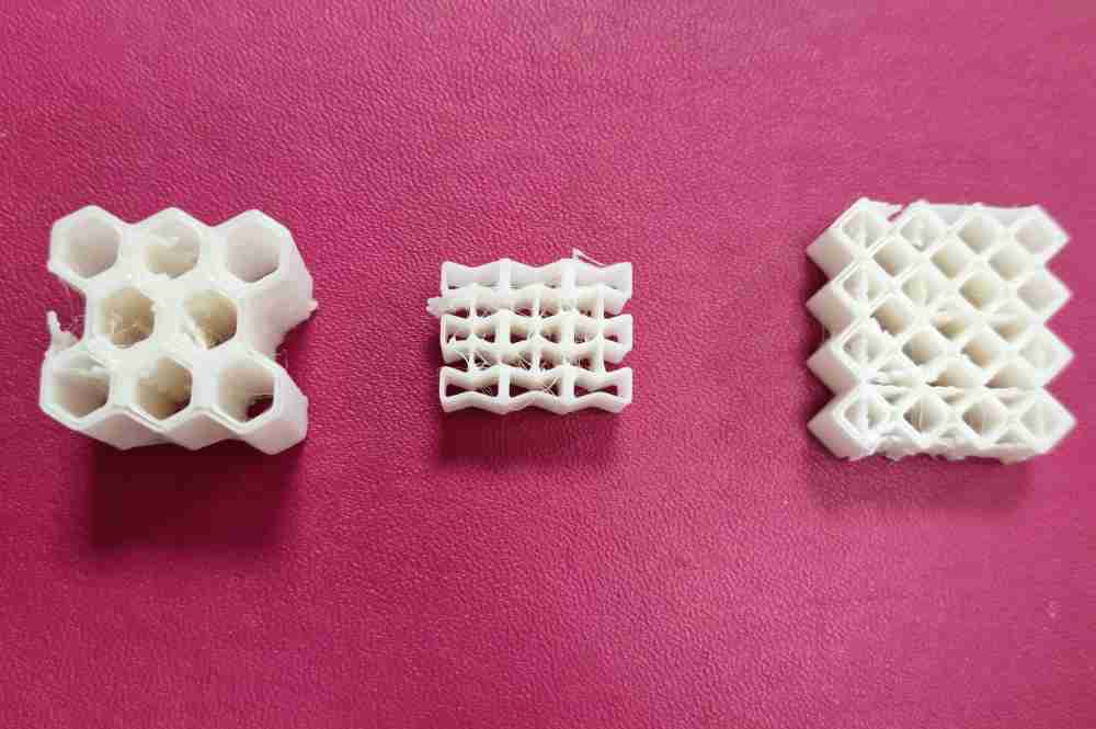 TPU testing.
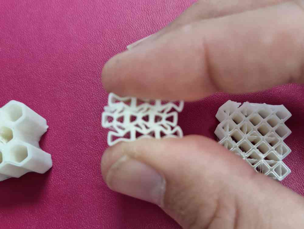
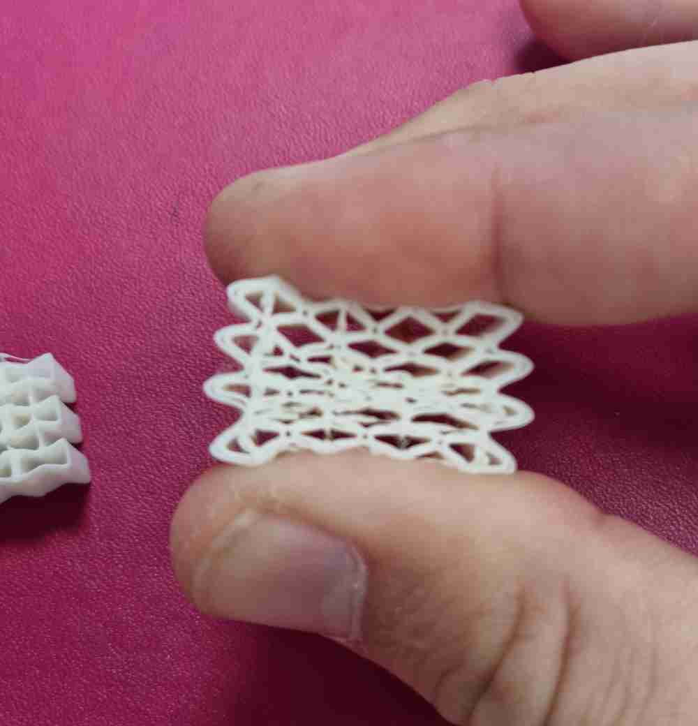
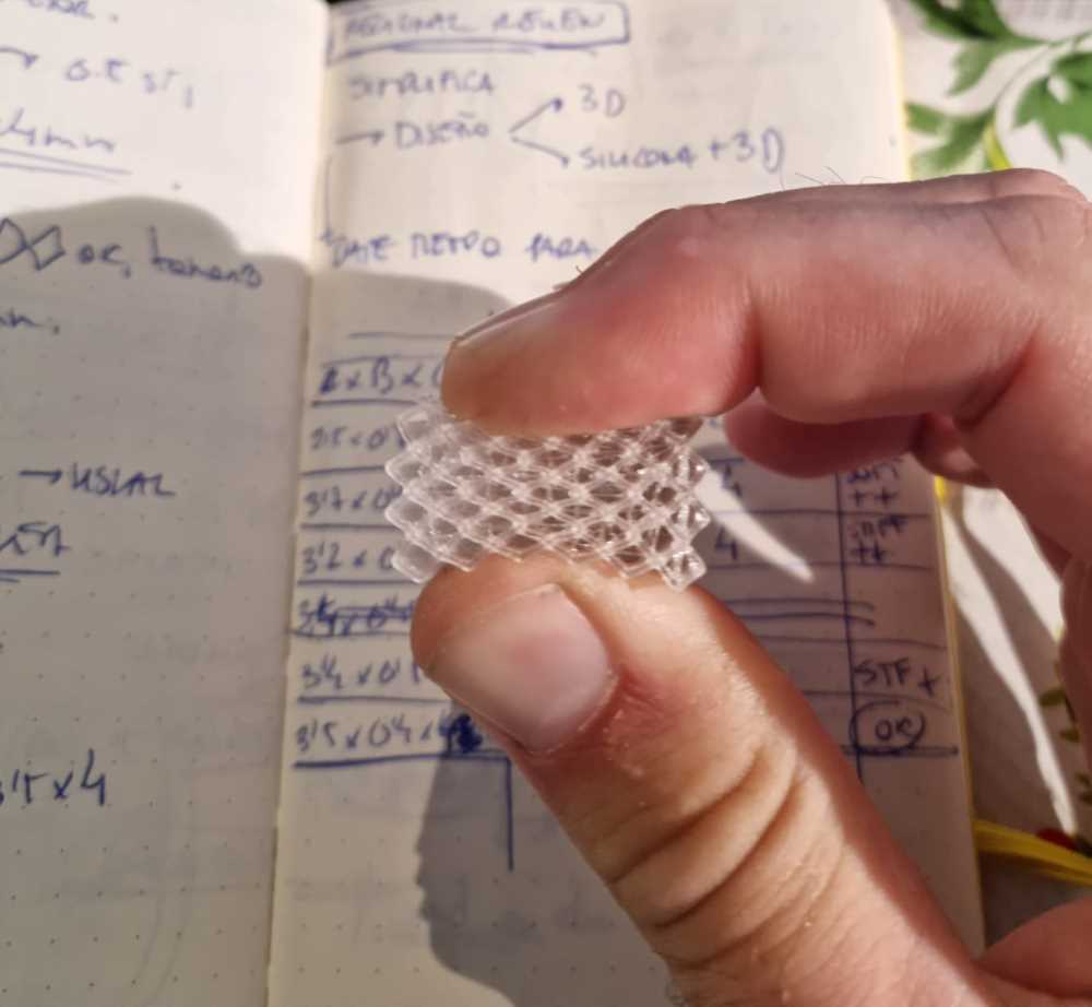
Now, testing the best pressure pattern design (diamond shape), changing sizes and widths and even testing as the infill pattern:
 Infill testing
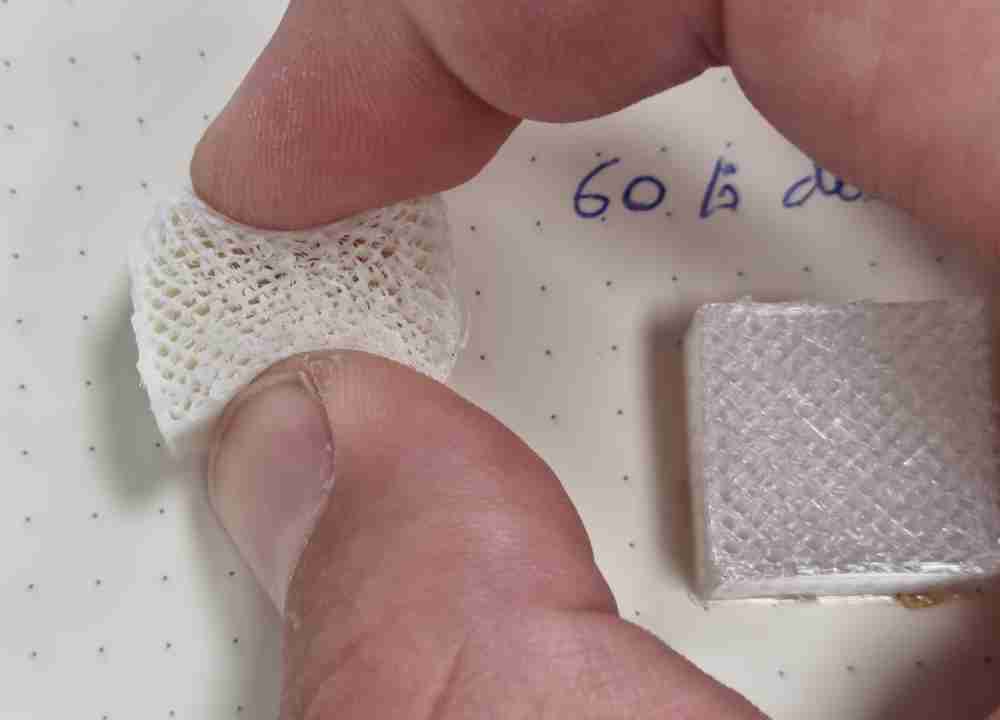
Here´s a pressure test video:
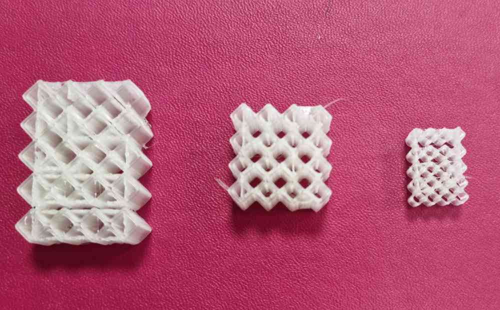
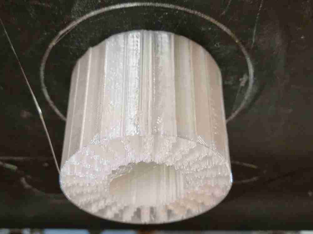
Finally, you can see some 3D printed tests for iteration purposes:
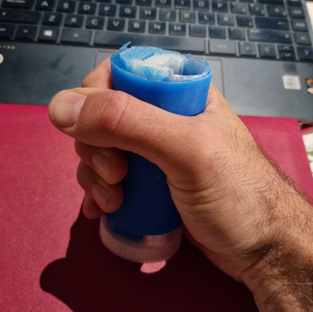
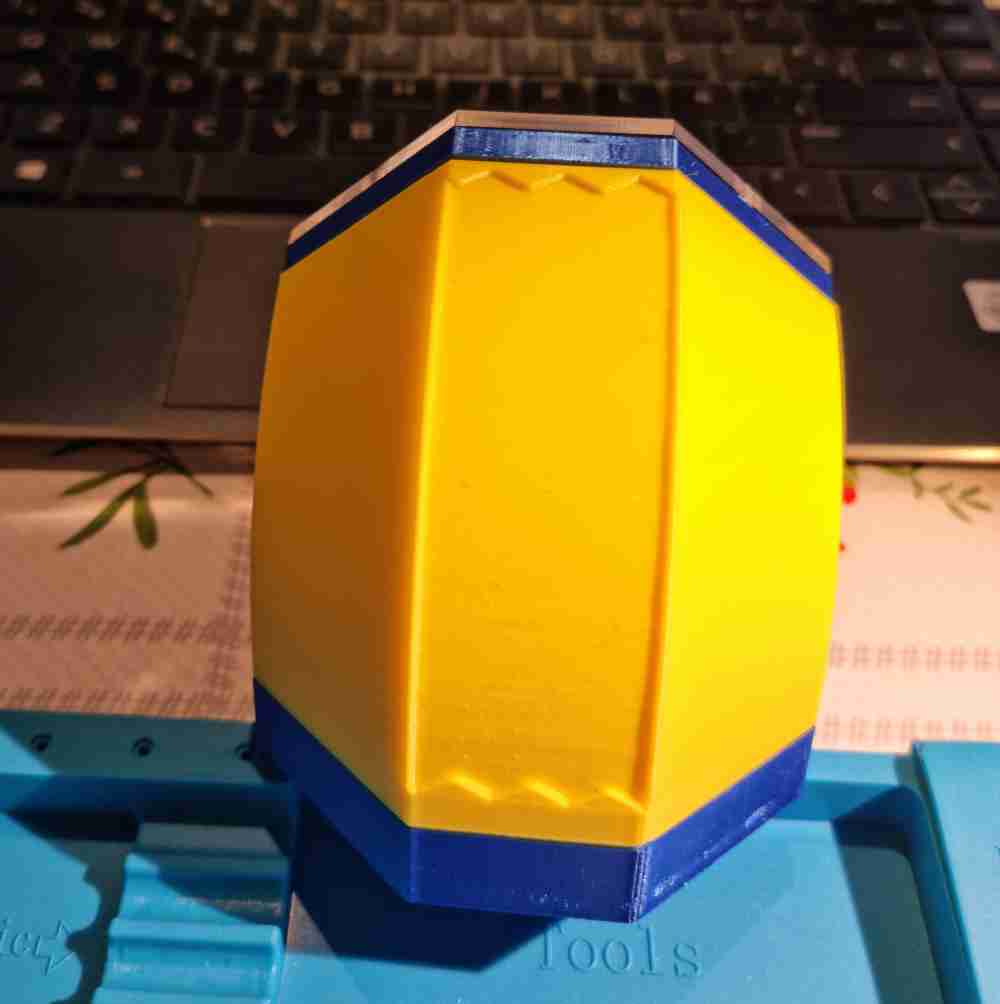
Finally, I opted for the rectangular shaped flexible TPU (92A), as it fitted best my interests regarding my final design, being more stable and easier to build as it will have a rigid 3D printed inner structure that will give stability and will permit better measurement outcomes, facilitating the use of two copper electrodes as you will see later on.
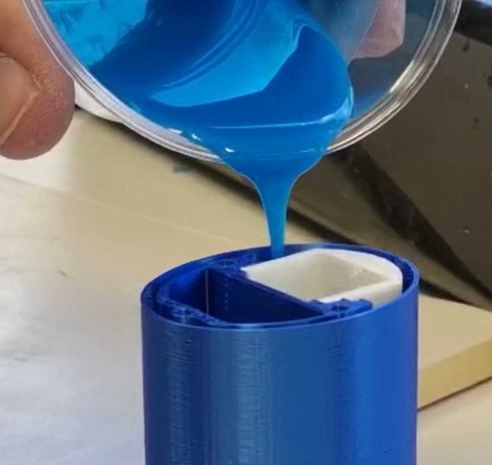
SILICONE INSERT MOLDING
AIM: As mentioned above, I got selected in the random review in the input device week, and Neil gave me some very useful indications, such as to use only one material and "chip" parts of it away. He also recommended to test with insert molded silicone, so that´s what I did.
In order to achieve it, I put on practice all that I learned at WEEK 09, molding and casting.
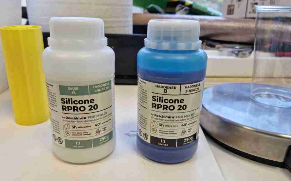
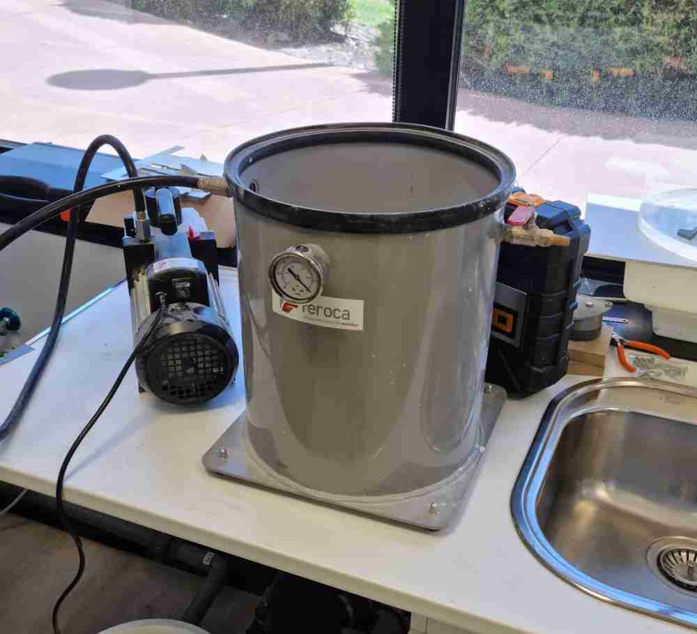
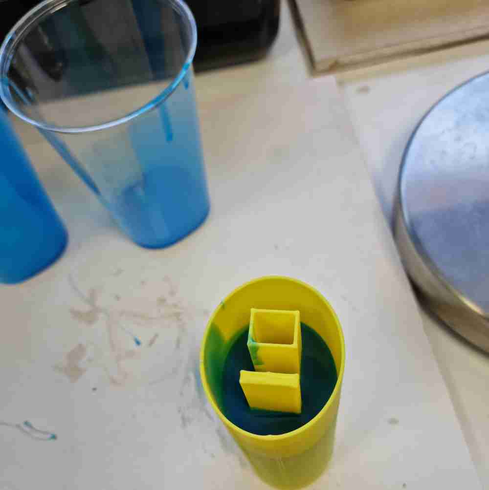
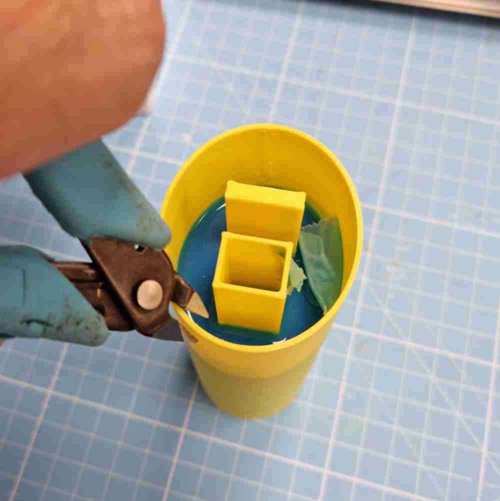
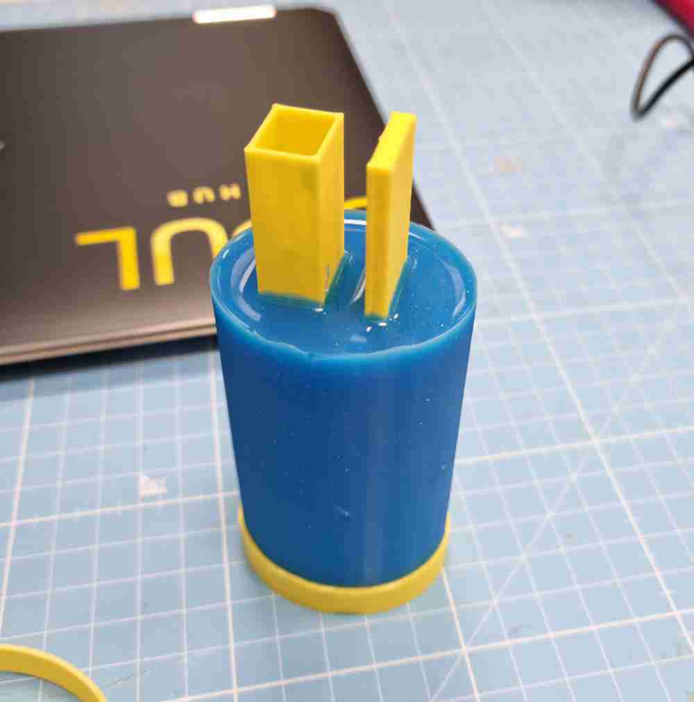
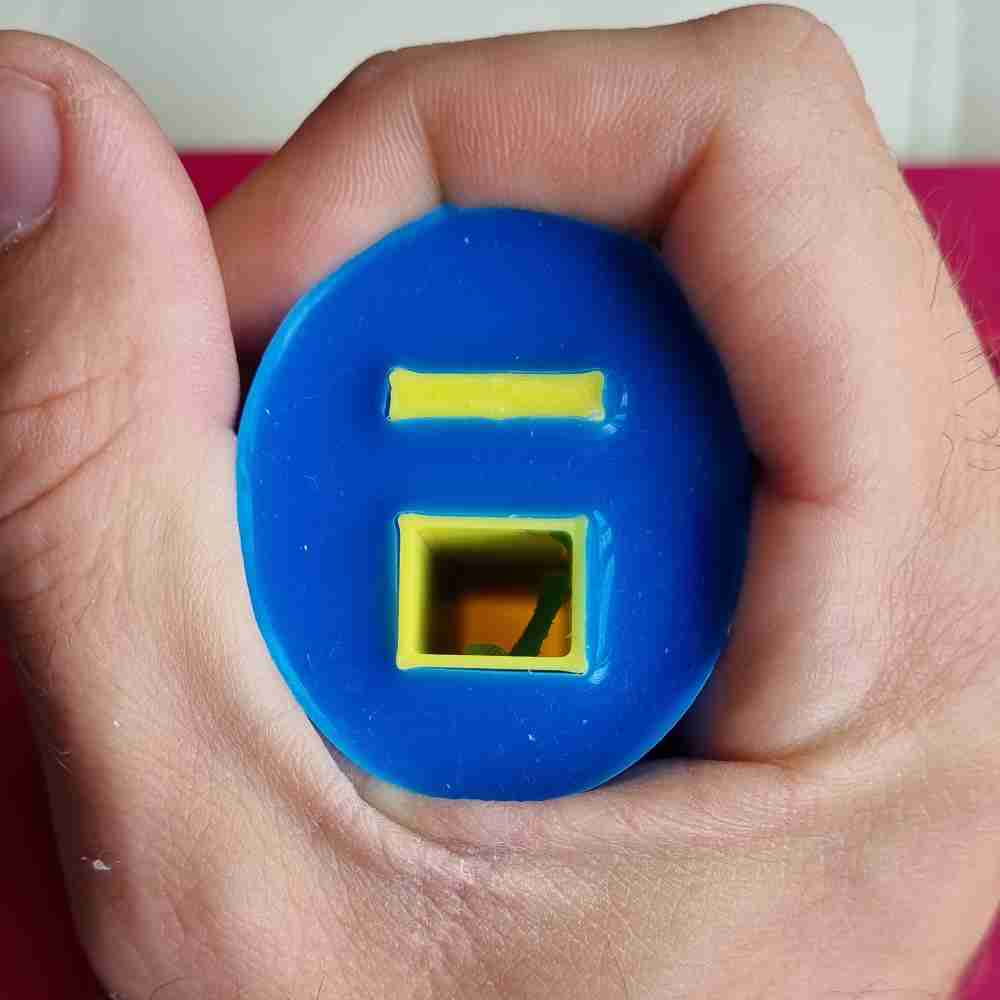
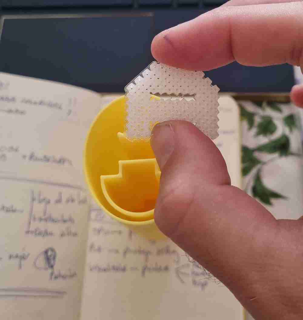
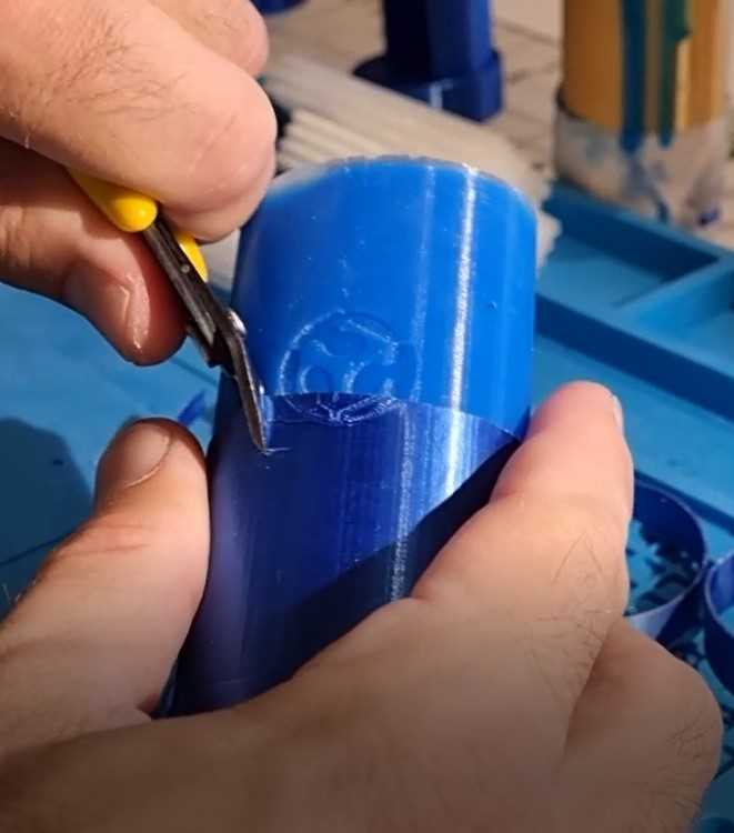
After a first test with silicone, it doesn´t fit my needs as the material to make the inner structure due to the fact that it´s too soft. So, for a next step, I tested the silicone as an external coating, working purely as insert molding for a better grip and aesthetic look. Here you can see the final process with silicone and the grip design:
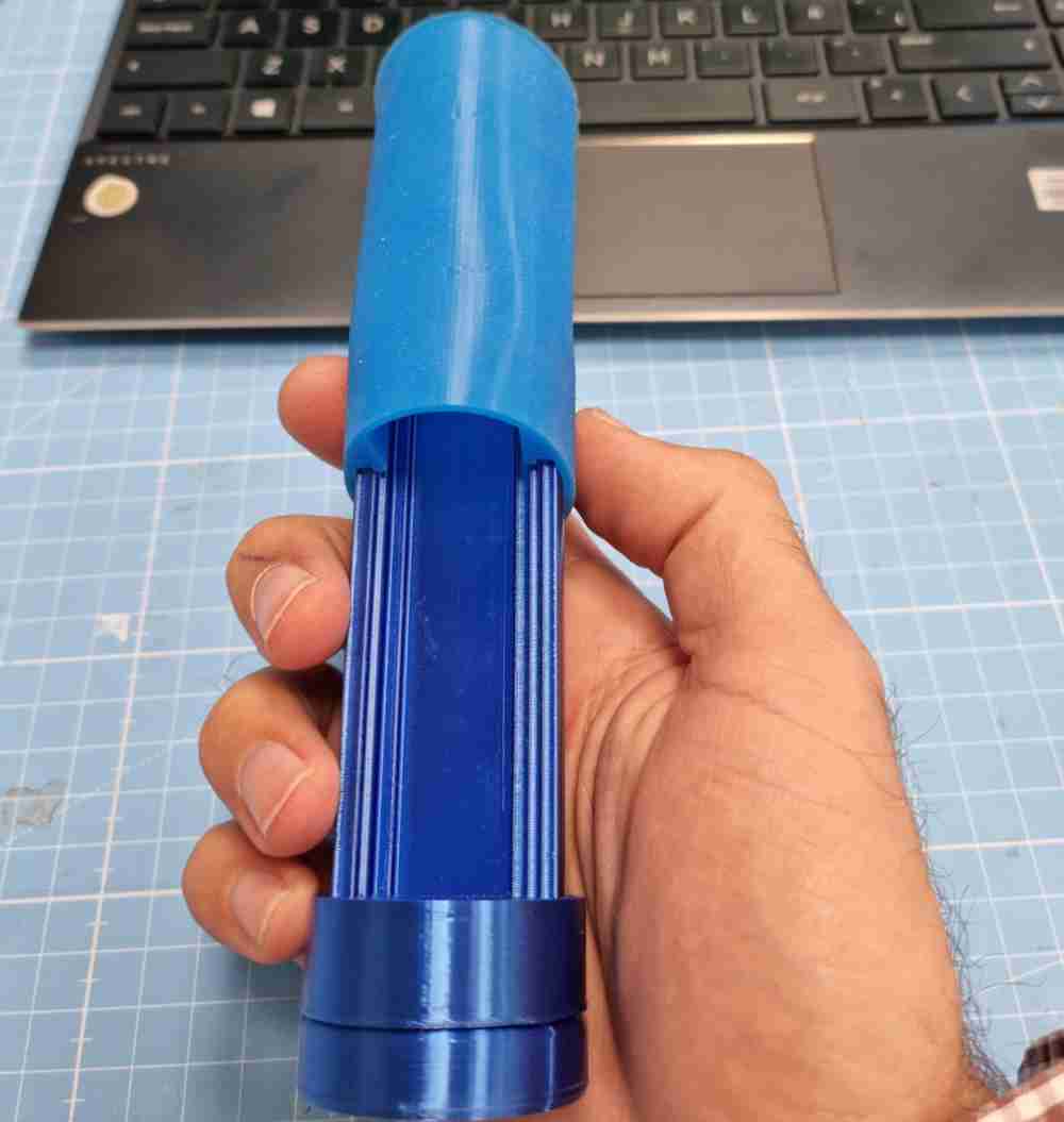
Here´s the final silicone external moulding used in my grip device, I designed a very thin external layer that covered all the grip device. I poured the silicone between this layer and the inner structure, and once the silicone was ready I just "cutted" away the external layer giving a very solid and stable external silicone coating.
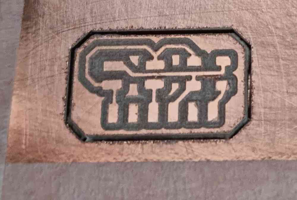
As I wanted to customize a little my final project, I used the Fusion 360 emboss function to add the logo to the external, curved, surface with very good results.
 Fablogo with emboss function
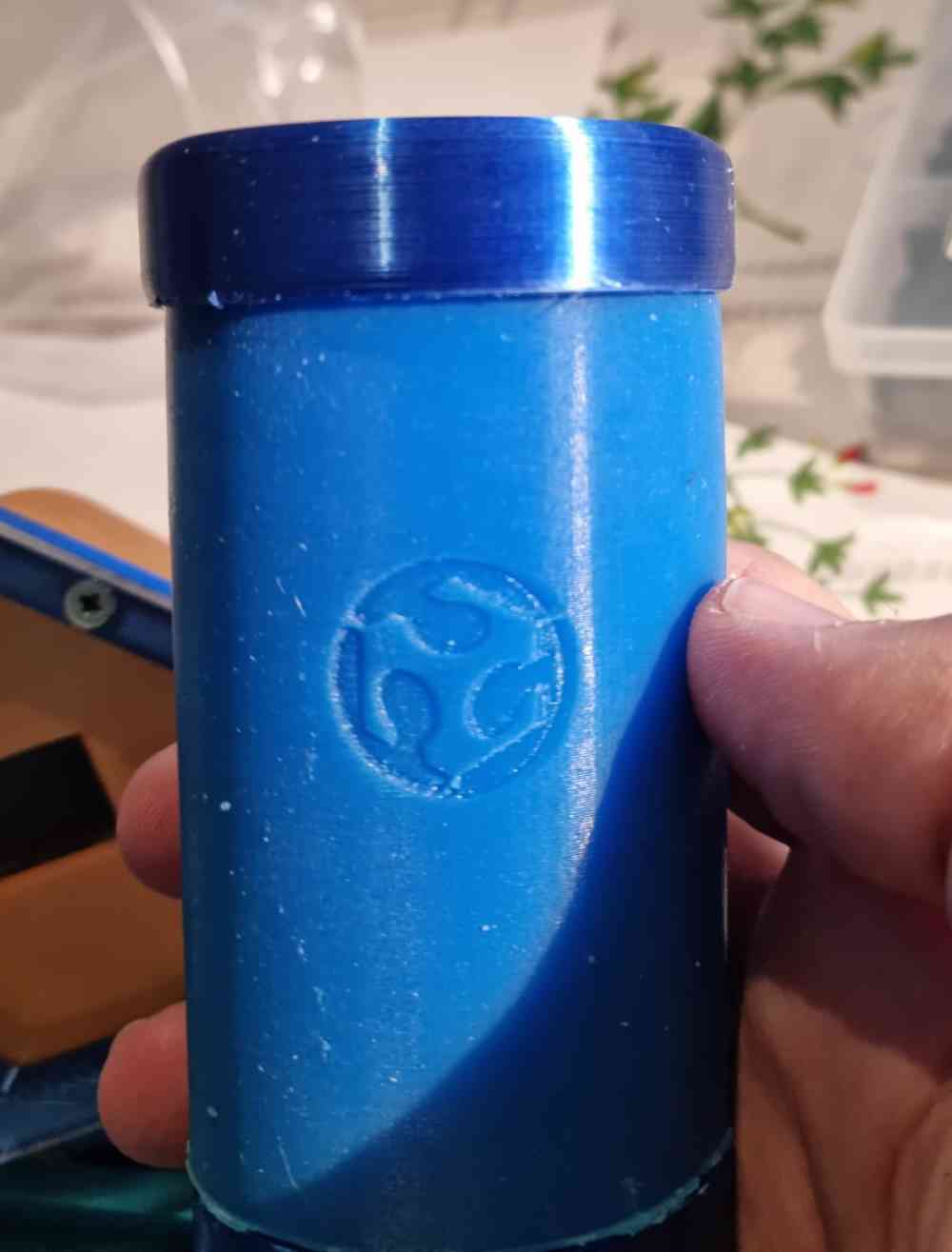
CAD DESIGNING
Meanwhile, as we progress and understand better the capabilities and properties of our 3D printing filament, we start to design, for a first spiral, our grip, which will incorporate and/or contain:
- A own pcb with an ATtiny1614.
- An 128x32 Oled module display.
- An own designed step response.
- An HC-05 bluetooth module.
- A 3.7V rechargeable Lipo battery
In order to design it, I used Fusion 360. We could say that one of my biggest handicaps is CAD designing, so i´ve spent (and still spending) a lot of hours learning to design, but i´m impressed by the big improvement i´ve done in the last weeks (and still have some days to go..)
FUSION DESIGN
For the CAD design, basically I`ll design a grip force device based on the best pattern design tested before, but being able to be created quickly with 3D printing additive procedures:
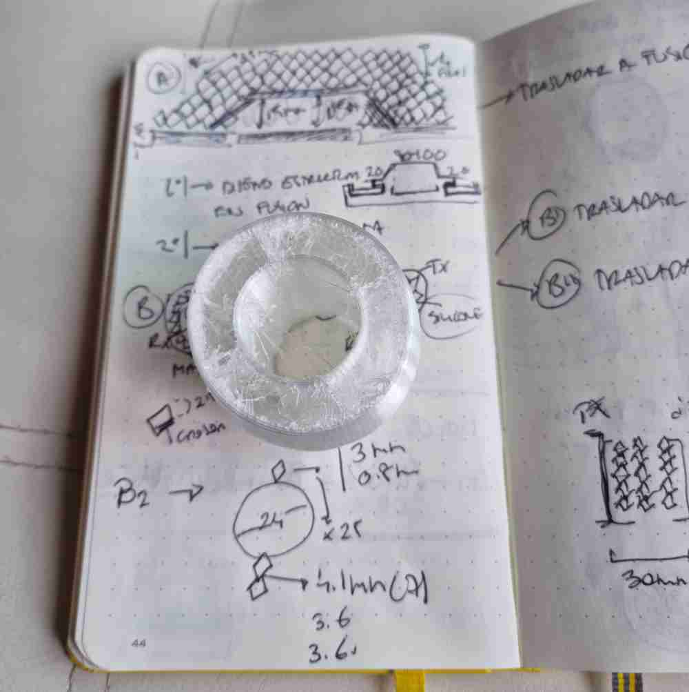
 Checking literature
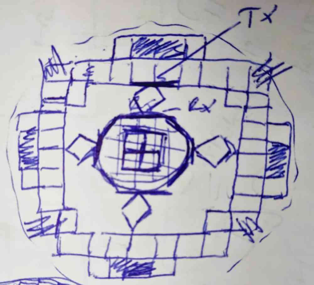
 First sketches
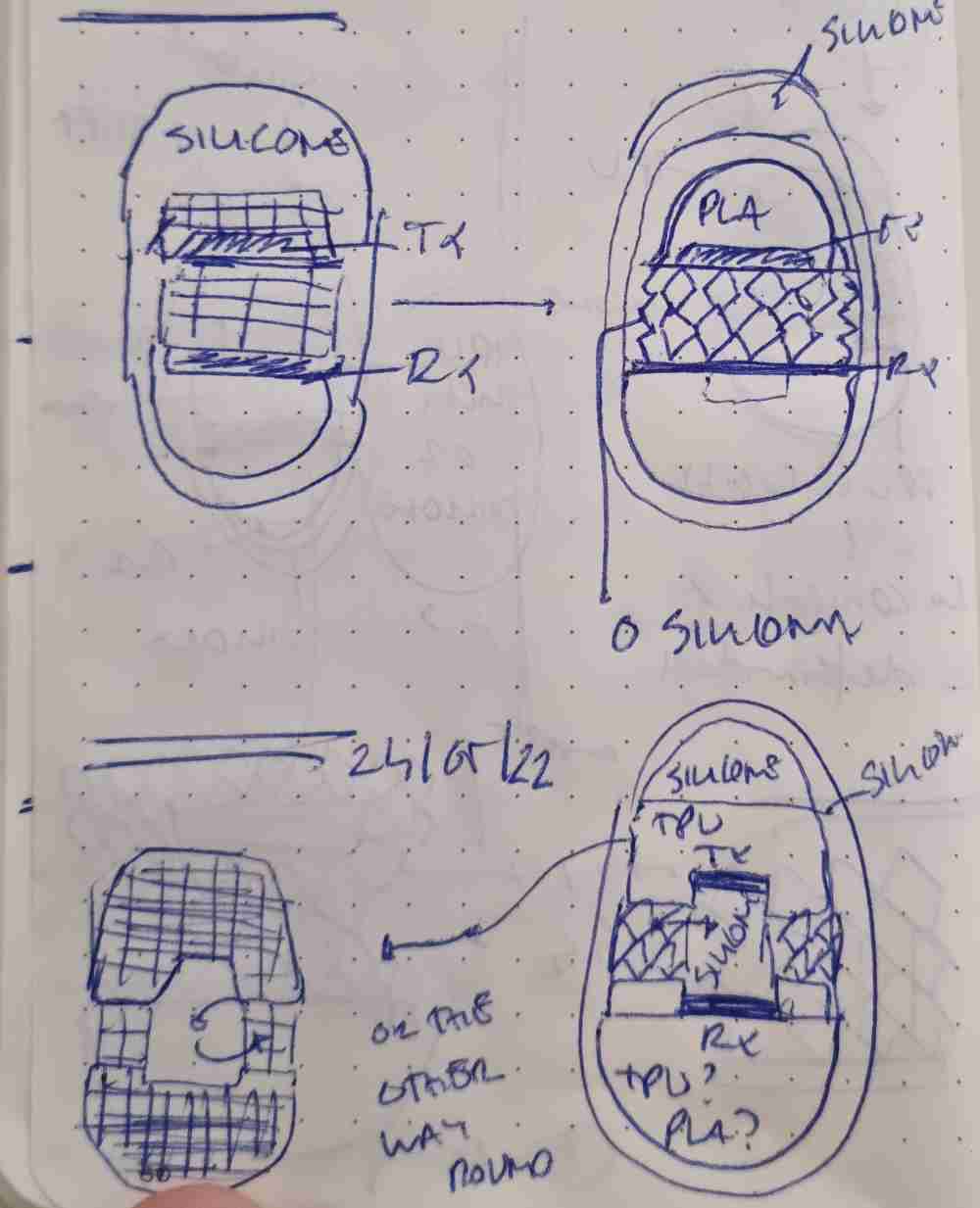 Final inner structure
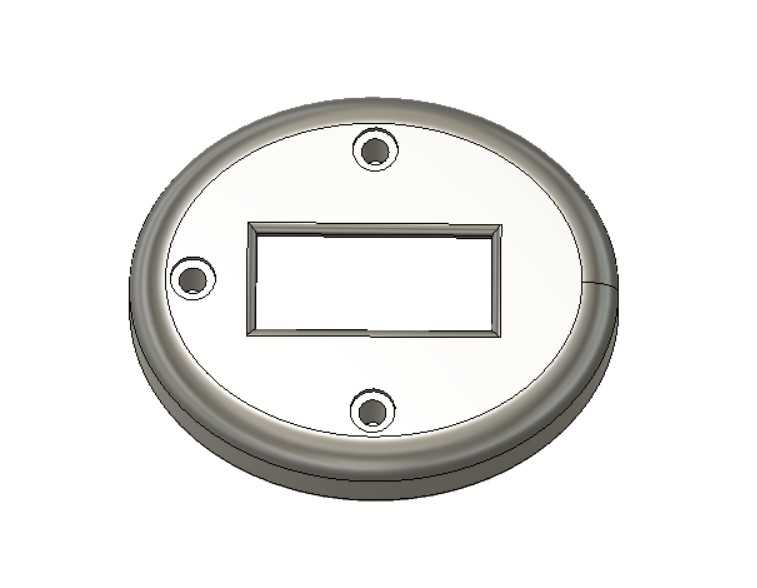
FIRST SPIRAL: GRIP DESIGN
AIM: As mentioned in my final project proposal, I want to design a grip made with digital fabrication. 3D printing, that can be able to measure grip´s strenght and that data being able to be visualized and stored in a personal computer.
In order to achieve it, i´ll do a lot of testing and iterations first to practice and learn, and secondary to obtain the result I want from my design. So, my grip design will have two well defined parts, an inner rigid structure, with the aim of mantaining the structure, capable of storing the the components listed above, and designed for the insert mold proceddure, and a flexible (metamaterial-TPU designed) part, able to shrink and stretch depending if we add pressure or not, making both plates of the step reponse getting closer (incresing the value measured) or going to the initial position (initial value = 0). This flexing capability must permit over 70kg/cm2 of pressure, that is 10kg over the normal strenght that any male adult should have. In order to have a clinical utility,
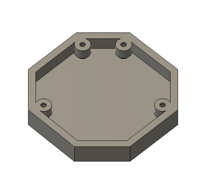
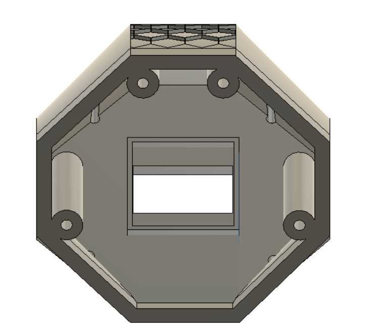
GRIP INNER RIGID STRUCTURE
 base
base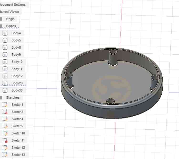
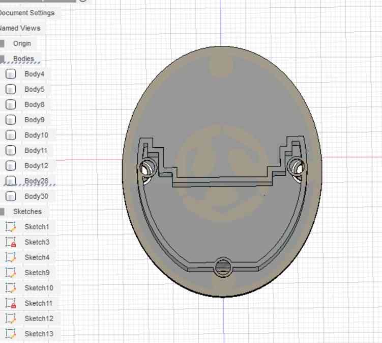 inner structure
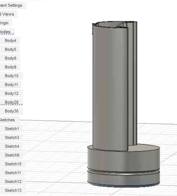
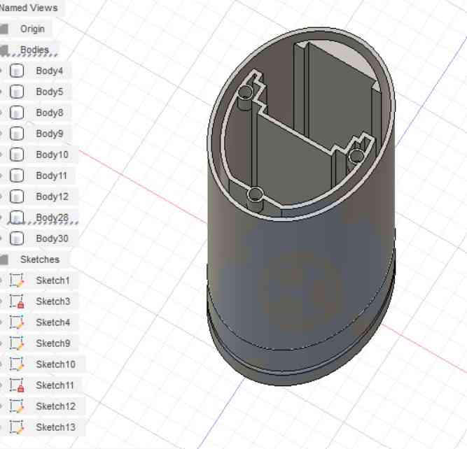 external wall for insert mold
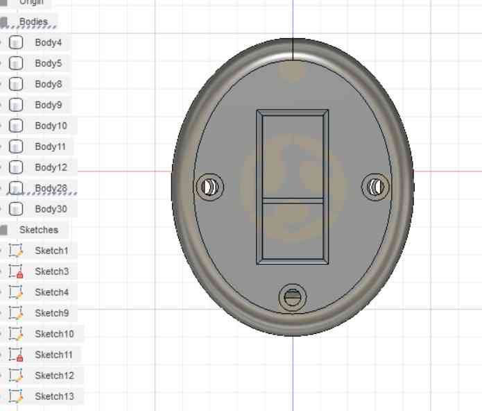
 upper part
As you can see in the images above, this structure is divided in a bottom part, where the LiPo battery and the pcb board will be placed, a middle body where the flexible part will be mounted, but also with space to store the HC-05 bluetooth module and the dupont cables that will connect the Oled module located on the upper part with the board located in the base.
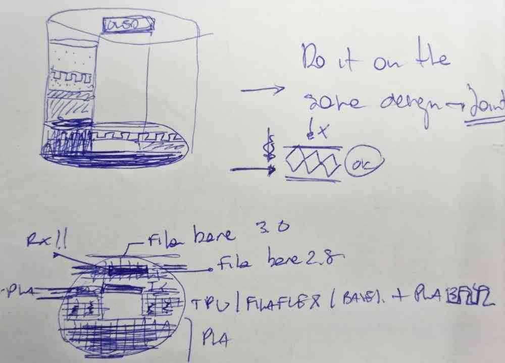
For the insert molding, I designed a different version with thin external walls that will act as a "box" to contain the silicone. We will use a 20 shore Silicone to do it.
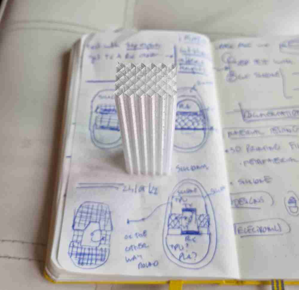
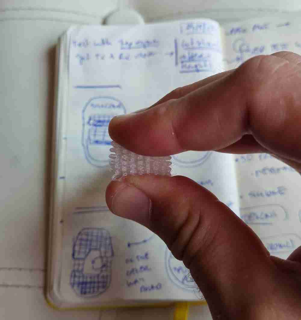
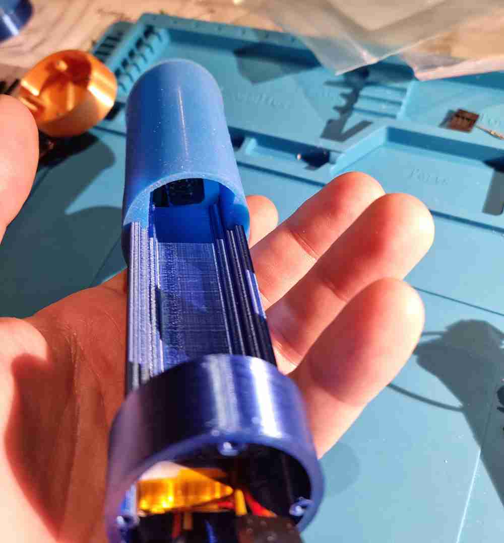
FLEXIBLE METAMATERIAL-DESIGNED PART
Once we´ve got our first versions of our grip, we will combine with the flexible-TPU filament, that will act as the "resistor" that will measure the pressure made by the grip strenght. So, to test it, we´ll design the diamond shape with different parameters (size, width and space) in order to find the best performance for our needs. Size is the lenght of each of the diamond shape faces, witdh is the width of the line, and space is the distance between each figure. To test them, we used them with our designed and built step response as you can see below (in the electronics production).
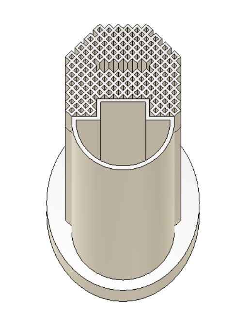 metamaterial + structure
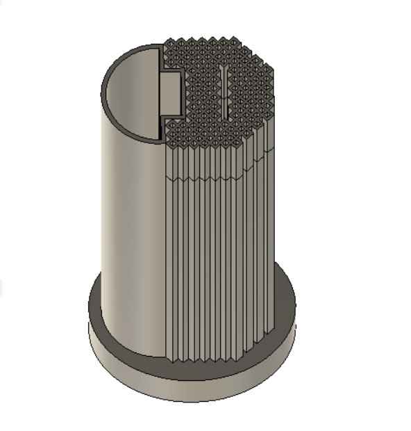
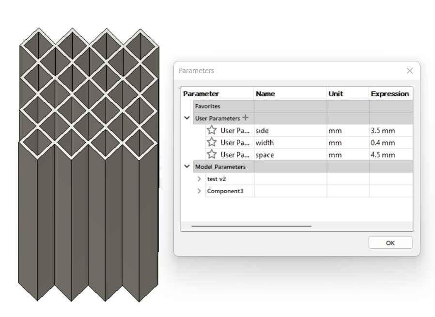 changing parameters
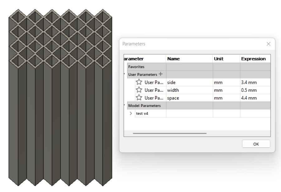
Here below you can see the videos of the CAD designs.
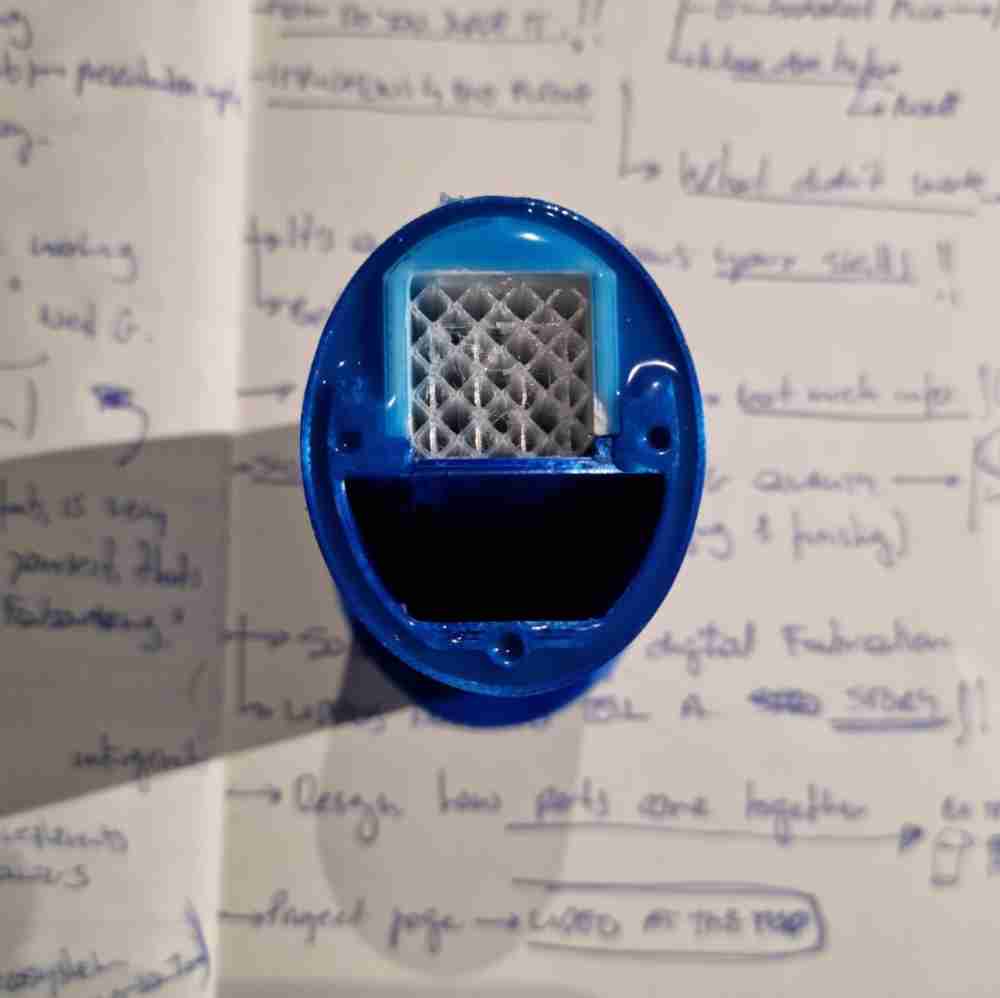
Finally here you can see how some of the first test resulted, however, without the electronics for now:
 With the silicone outer mold
And as we can see in the tests, it works fine. Giving a comfortable grip and also covering the inner structure. So it´s time to go to the electronics! (while we finish our final CAD design).
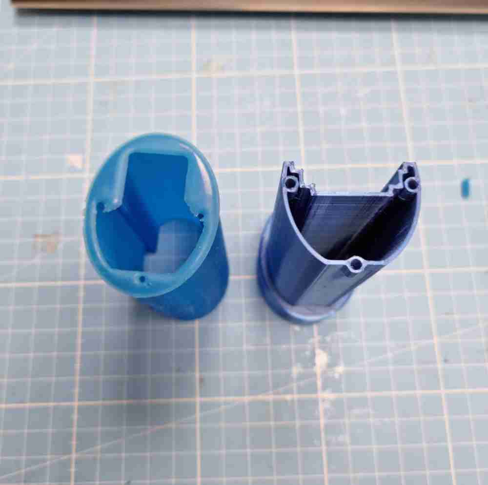
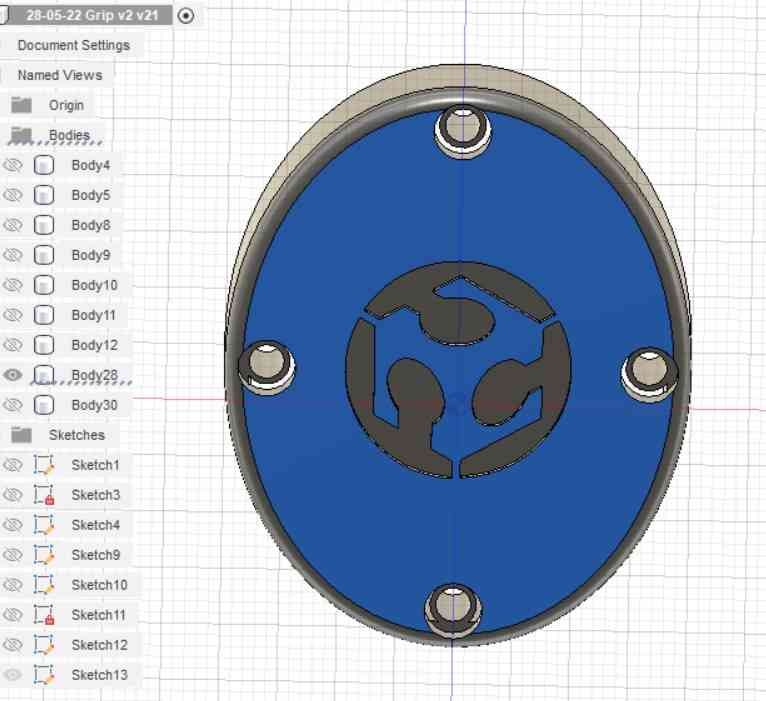
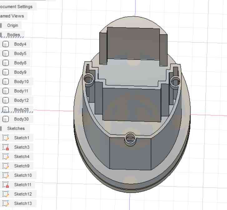
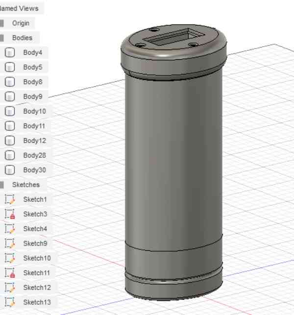
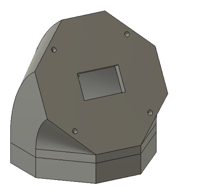
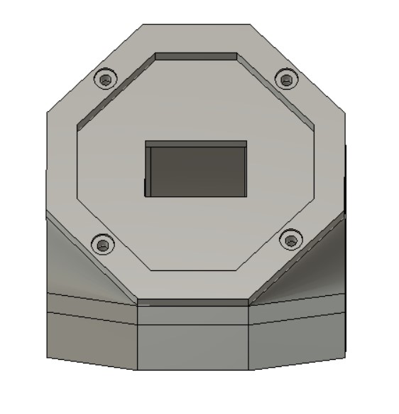
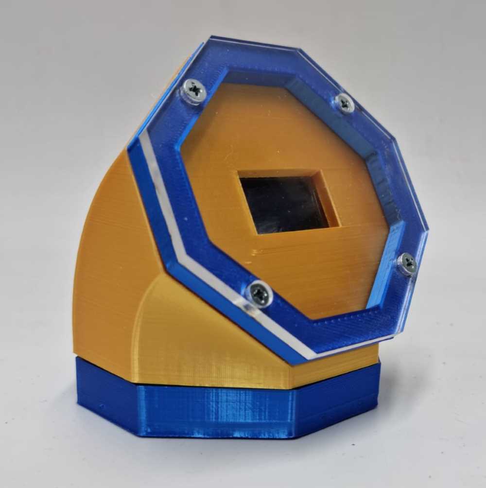
Once all the tests and iterations were made, with the time I had available, I developed the final design for my grip. Here below you can see the three parts of the structure:
 top segment for Oled display
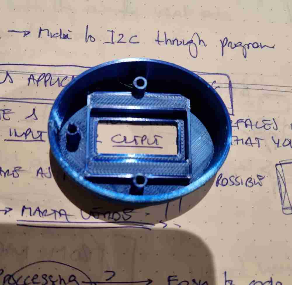
 Bottom segment
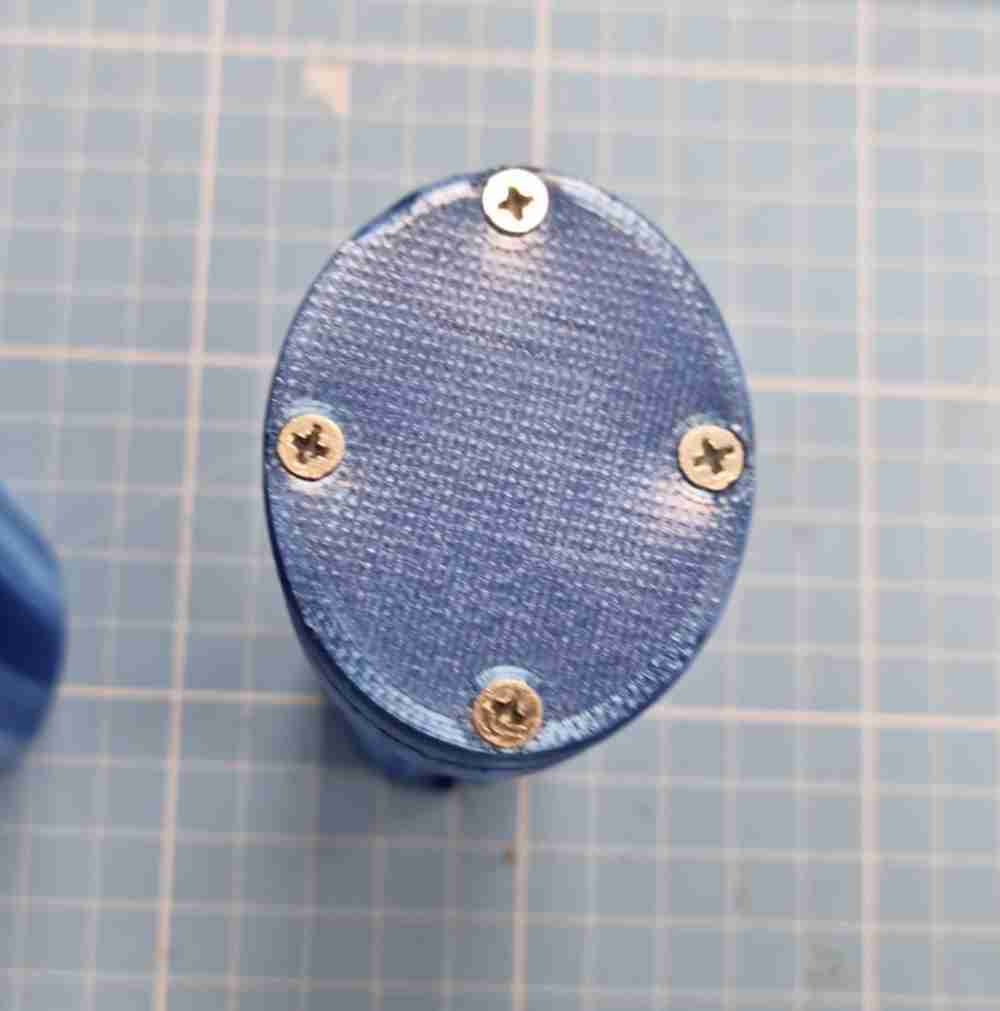
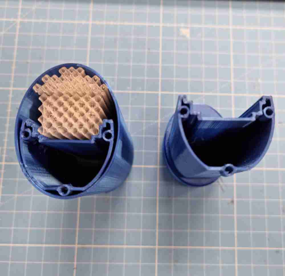
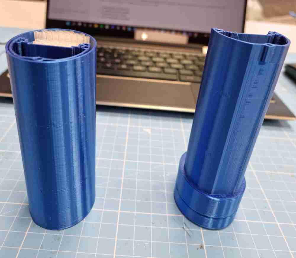 Grip body
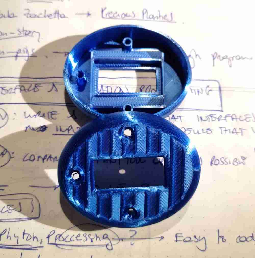
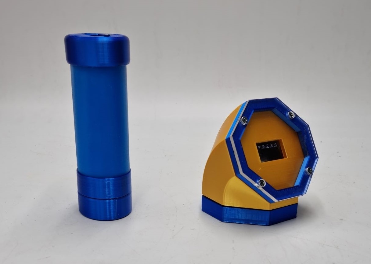
second SPIRAL: DISPLAY DESIGN
But, before going to the electronics, I went for a desing second spiral, I want to design an external display device were you can visualize the results obtained in the grip device. So, my aim is to create a dispositive with:
- A own pcb with an ATtiny1614.
- An 128x64 Oled module display.
- An HC-05 bluetooth module.
- A 3.7V rechargeable Lipo battery
And this means that my hand grip device will connect via bluetooth with this second device, through wireless master-slave connection.
Here you can see the initial tests, 3D printing and laser cutted top layer.
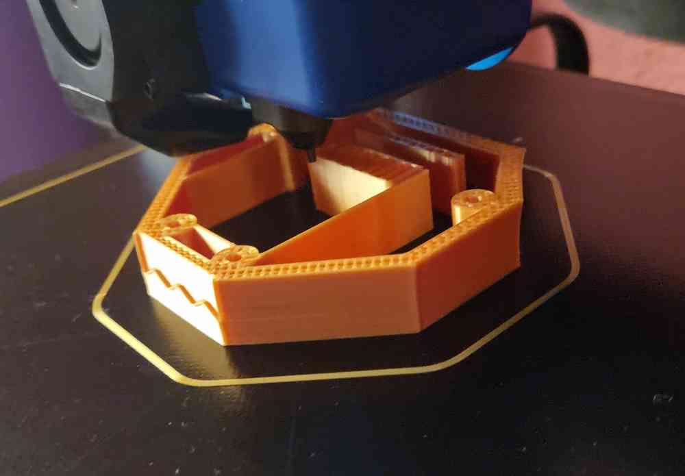 3D printing.
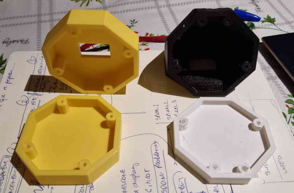 First tests.
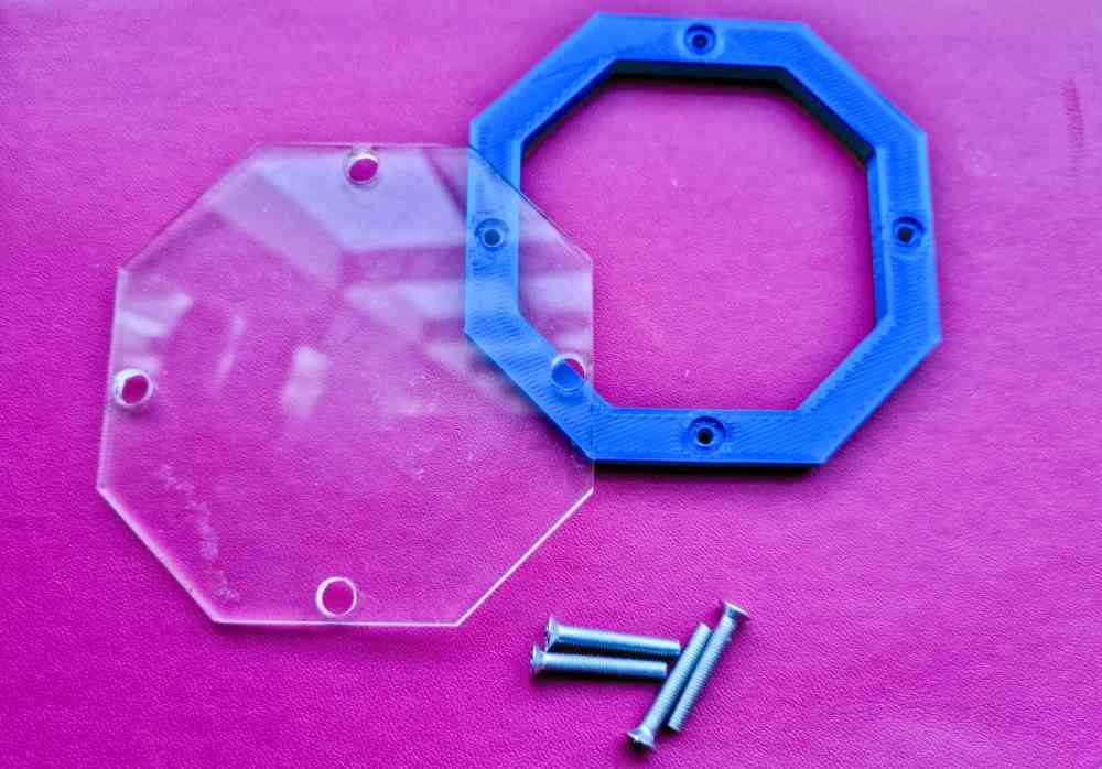 Top layer.
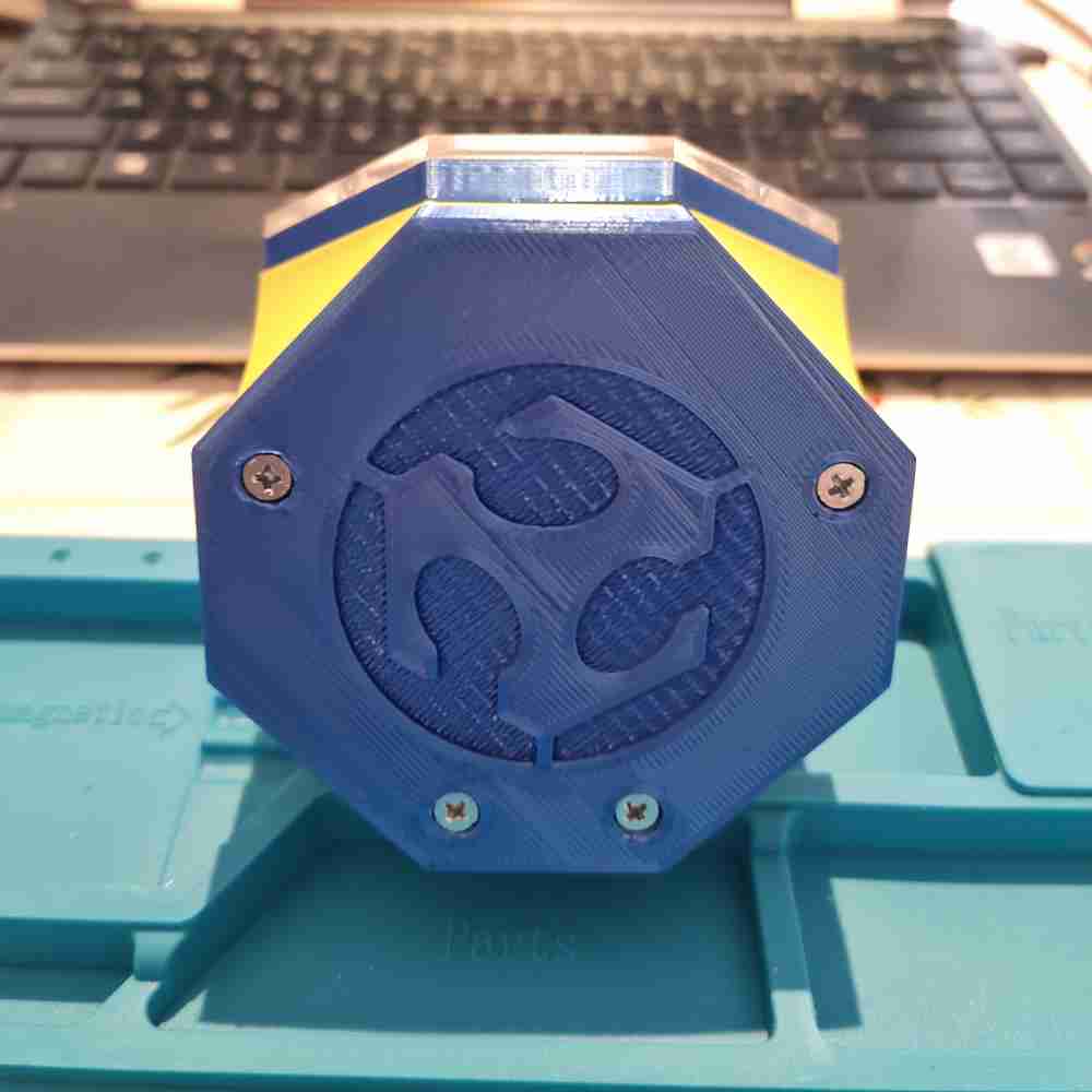
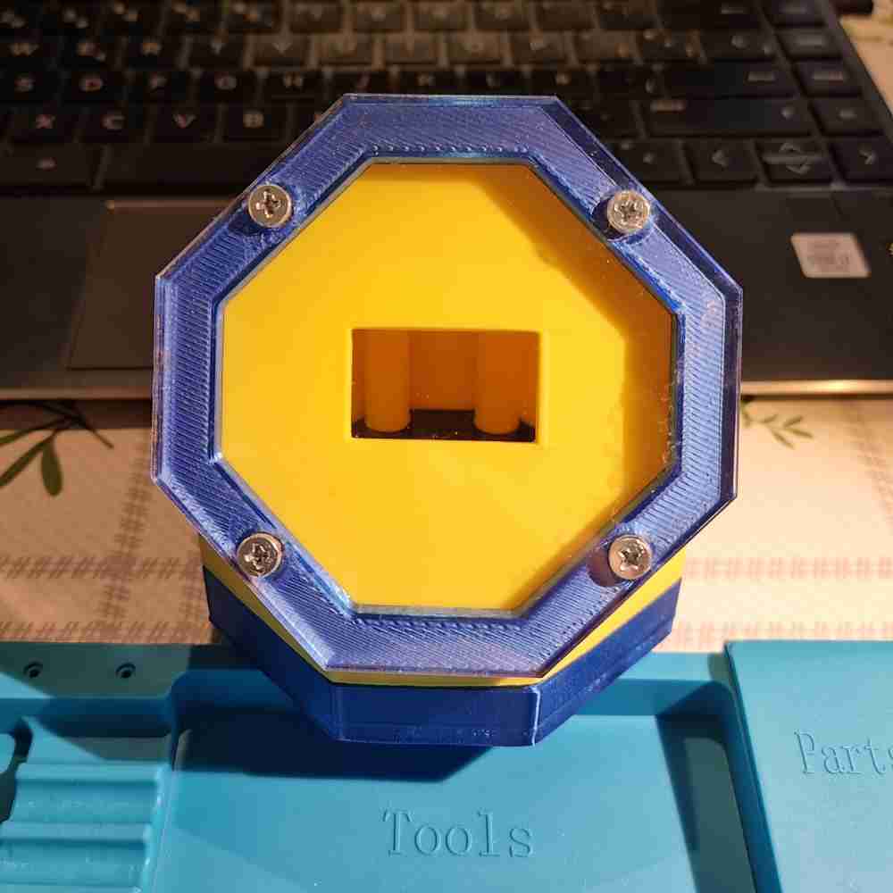
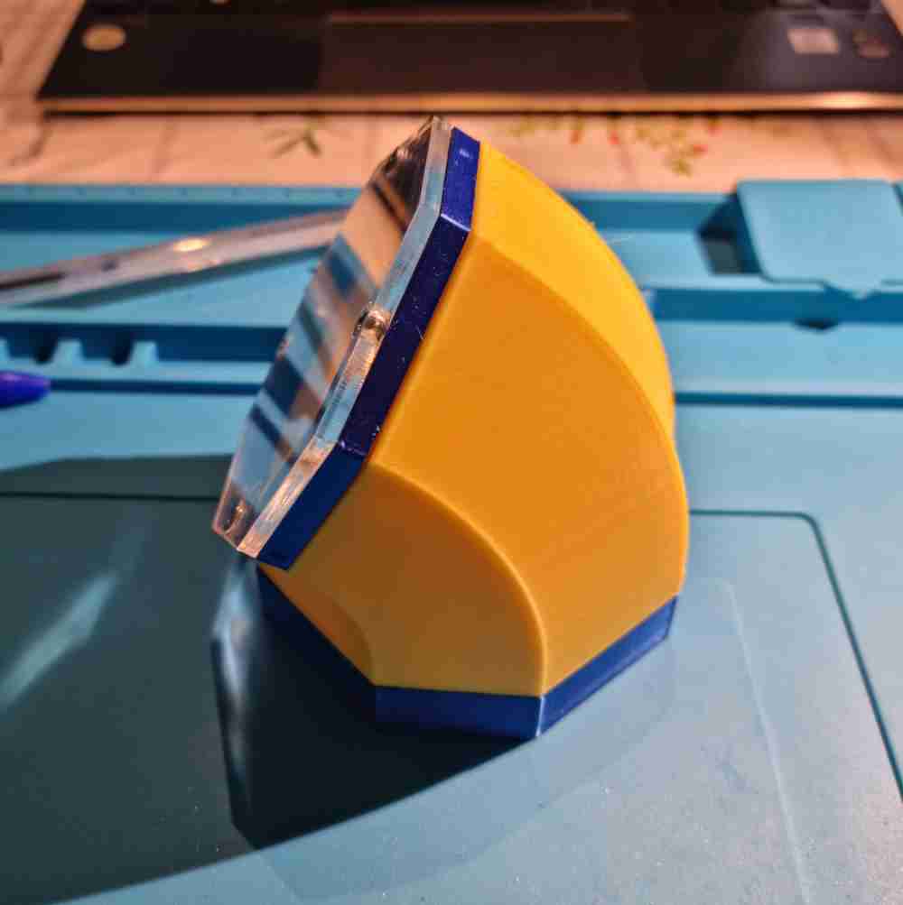
And finally you can see how it looks once its assembled with the 3D printed and the laser cutted acrylic assembled together:
As for final thoughts regarding CAD, it´s been by far the process that i´ve struggled more due to my lack of experience. I needed to invest a lot of hours in order to be able to even start to get something useful from the Fusion 360 program that i´ve been using. On the contrary it´s were i´ve had the highest learning curve and now, after the final project CAD design, I feel comfortable enough to use it with confidence, and I could say I even enjoy it! Definetely having previous knowledge in CAD design is of great help for future Fab academy students.
ELECTRONICS PRODUCTION
In the first weeks, Initially , I couldn´t use the weekly assignments in my final project as I had no experience in any of them, so I couldn´t figure out beforehand how I could use them. But, when we jumped into the output devices week, I understood that I could use this week fot my final project, so as you can check below, this is the first week that I started investing time for my final project:
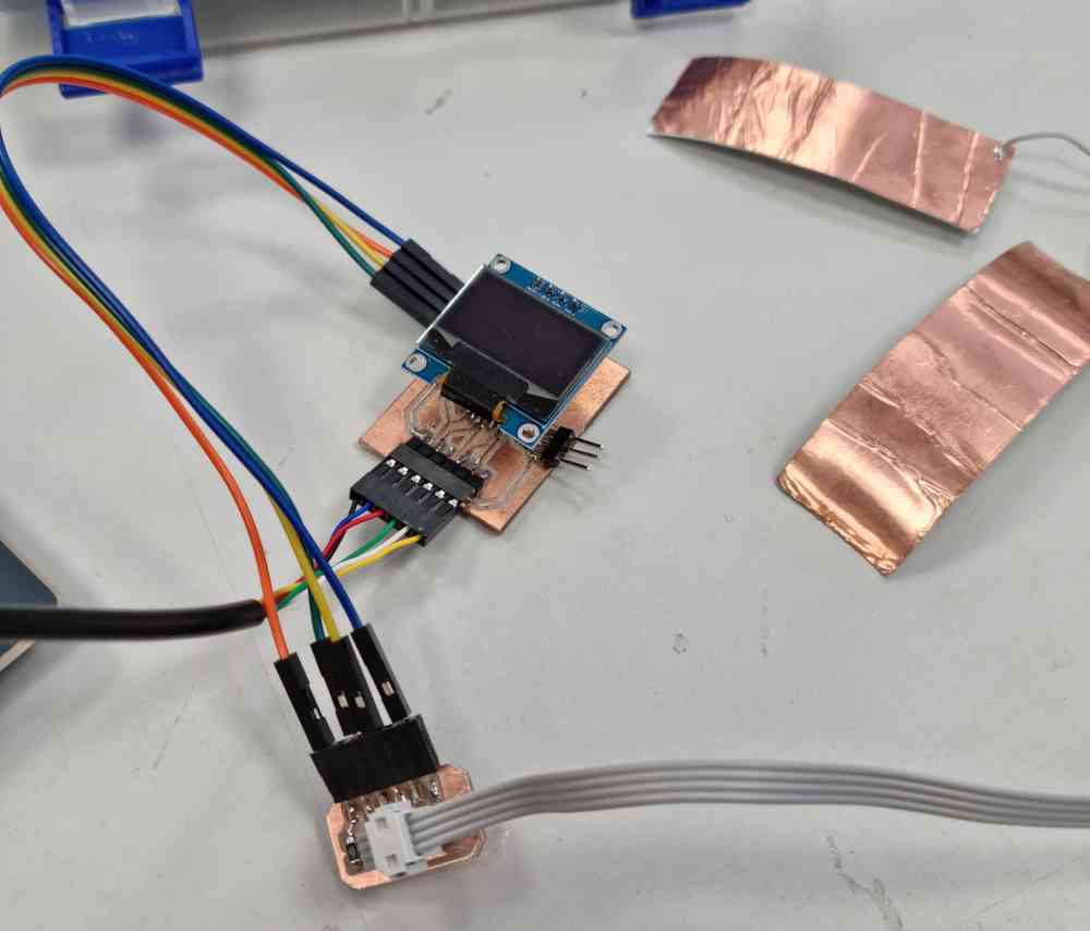
OLED MODULE: Output devices, WEEK 10 (04 of april 2022)
After making the Oled module work, I tested how I could use my OLED module for my final project, as I want to visualize the pressure/strenght value that the "patients" perform.
 2nd board with OLED + extra pins.
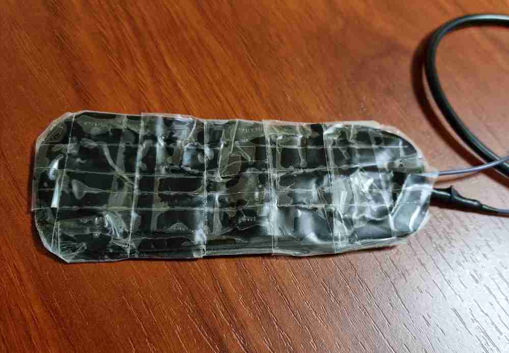 Home made velostat sensor.
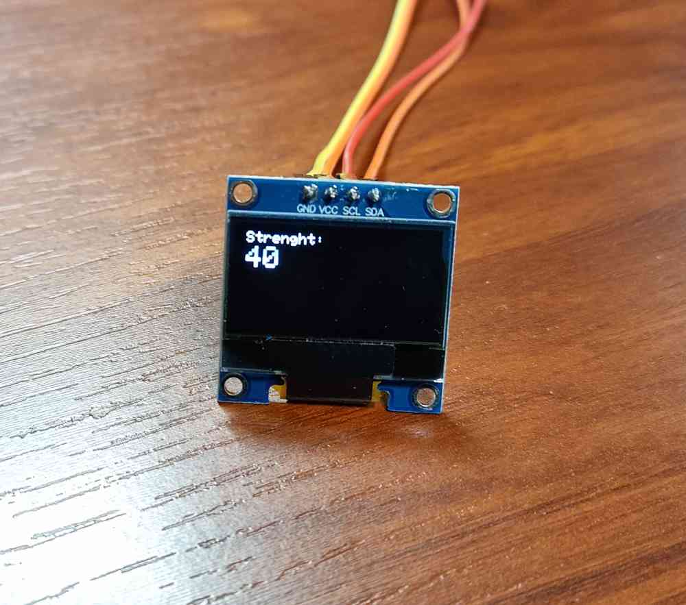 OLED´s "strenght´s value display.
Here you can check how it went:
You can see the complete workflow here Oled display + homemade pressure sensor, WEEK 10. And as you can read in it, I couldn´t use this type of sensor, as it has hysteresis invalidating the outcome measure.
Regarding my final project design, I will use the Oled module display in two different ways depending on the spiral:
- SPIRAL 1: I´ll use an 128x32 Oled module to visualize the data obtained directly in the hand grip design.
- SPIRAL 2: I´ll use an 128x64 Oled module to visualize the data obtained in the display module designed for this spiral.
 Spiral 1
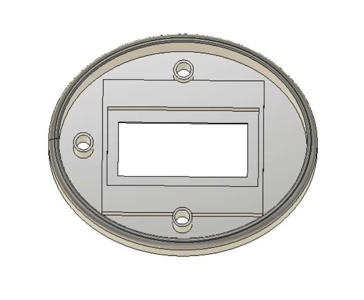
 Spiral 2
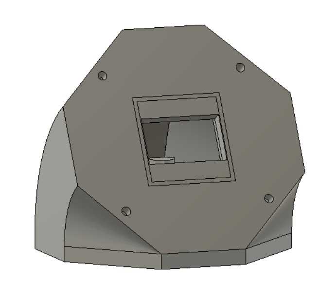
 128x34 Oled display
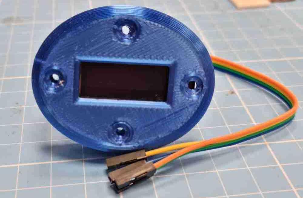
 128x64 Oled display
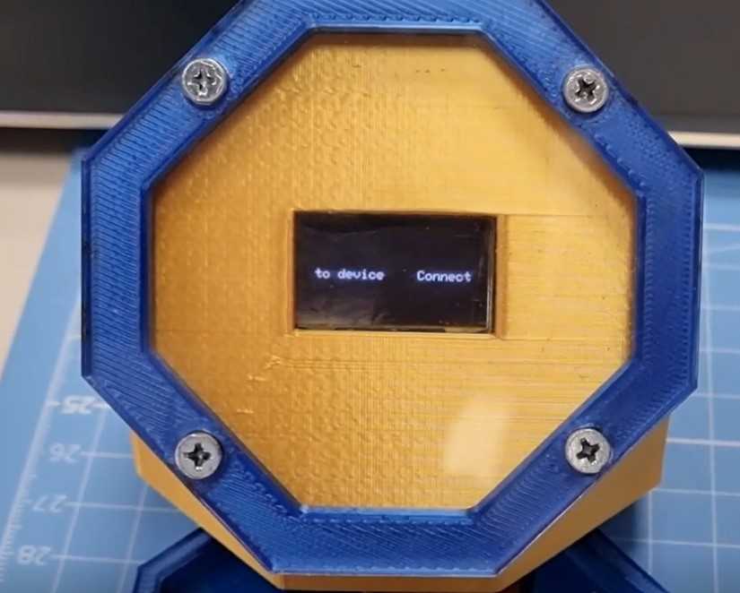
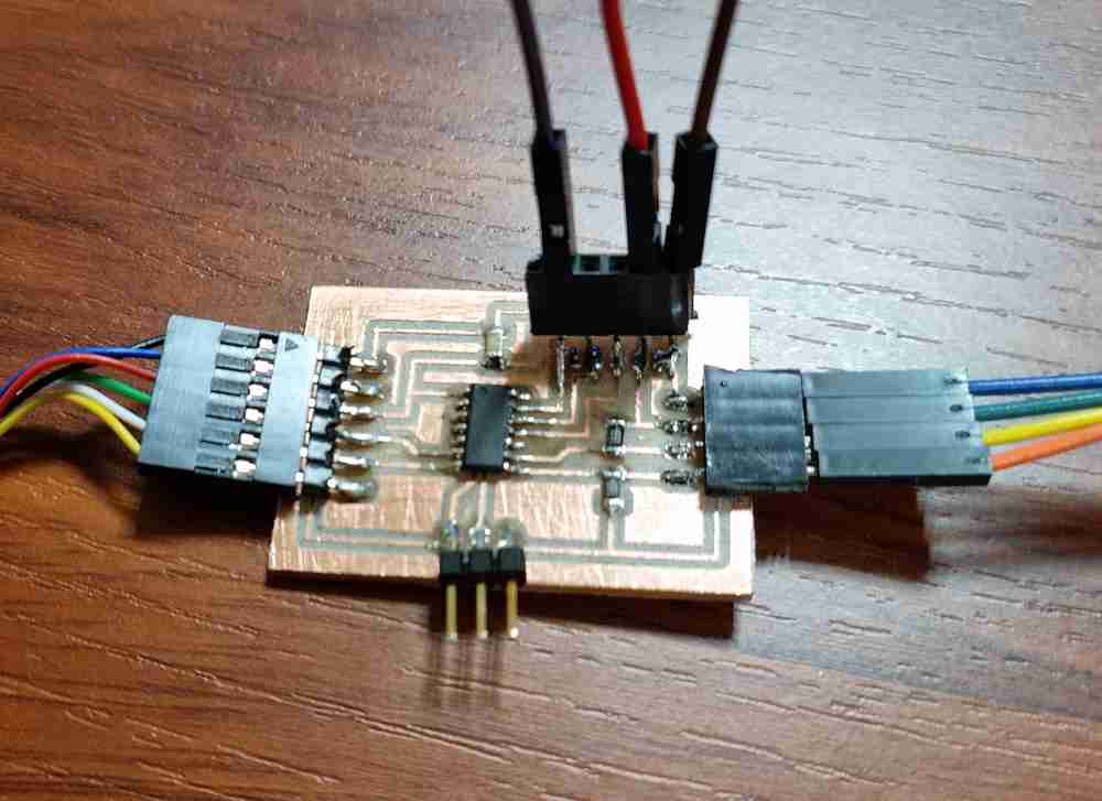
Finally, in this WEEK 10 I also designed, milled, stuffed and programmed the type of board I will finally use in my final project, with an ATtiny 1614 processor. As for lessons learned, its very satisfying to use the weeks assignment for your final project purposes. I´ve never done any electronics before, but it looks like I do well, as I haven´t had any debbuging or problems yet!
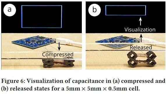
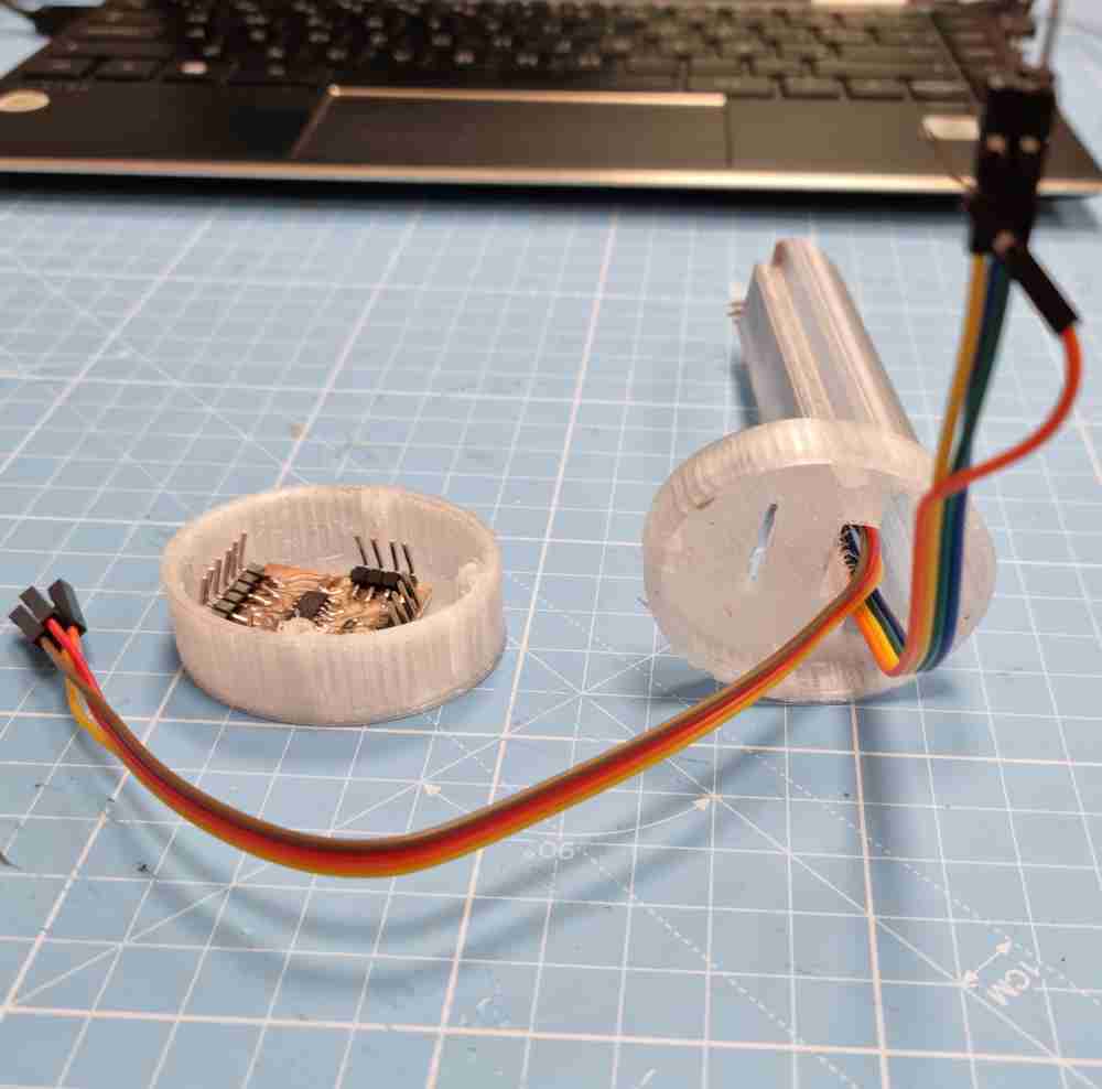
GRIP STRENGHT MEASUREMENT: building a STEP RESPONSE
AIM:As my primary goal is to measure the grip strenght/force that the user or patient does, in the Input devices, WEEK 12, I discovered the STEP RESPONSE, a perfect device to measure in a stable and consistent way the pressure/force that I need:
In the above mentioned assignment, I made my own step response:
 designed step response.
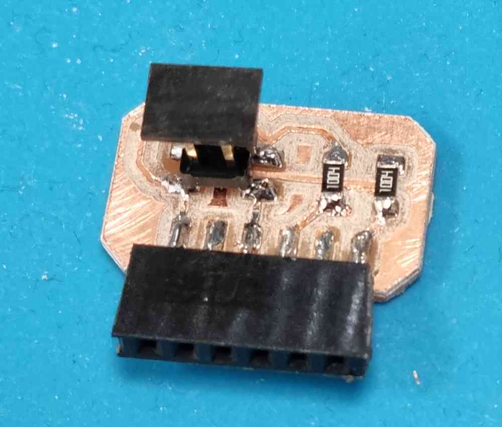
 board + step response.
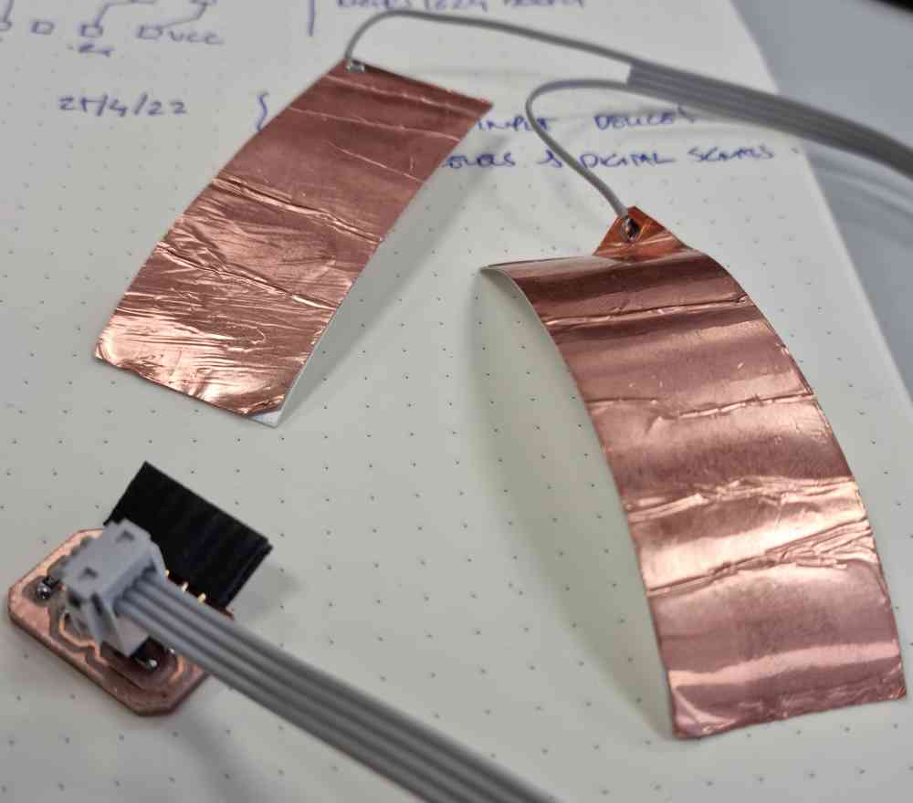
Here below you can see some images of the step response i´m going to use in my final project. I based it on Neil´s and Adrián´s Adrianino´s step response. But, in order to make it work with the best performance in my final project, I did some test changing from digitalWrite to digitalWriteFast, changed N (number of samples to take) and the delay, finding the best results in the code shown in the assignment mentioned before.
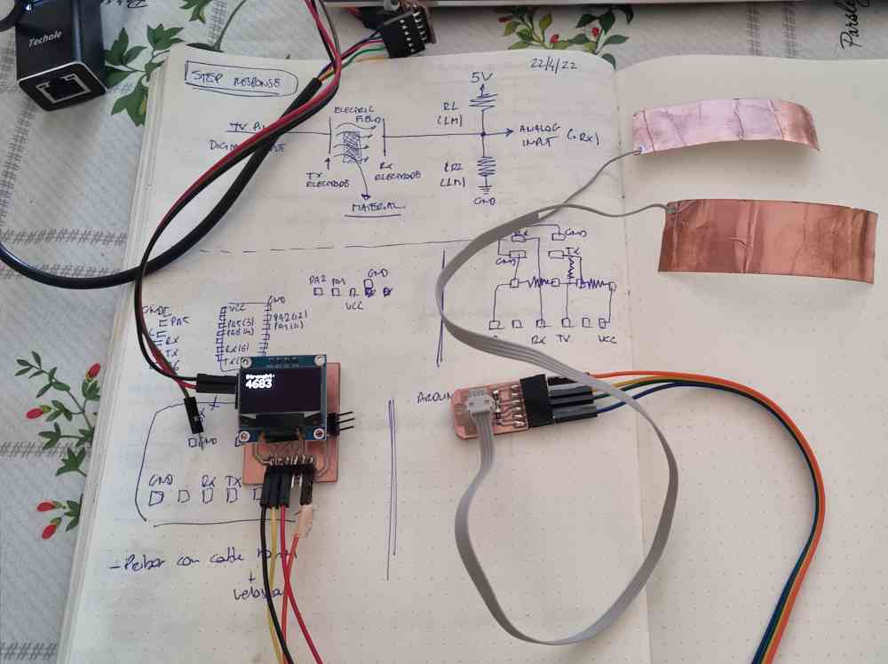 Step response and pcb connected.
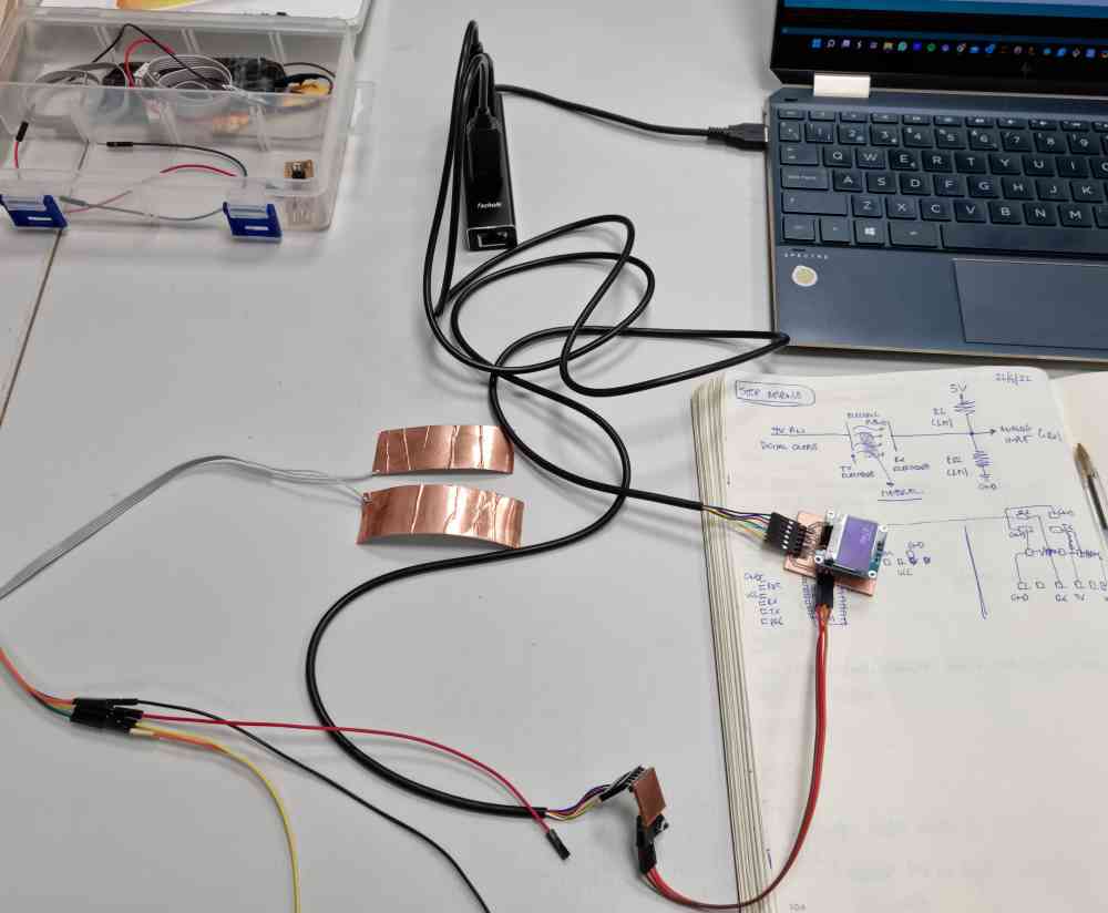
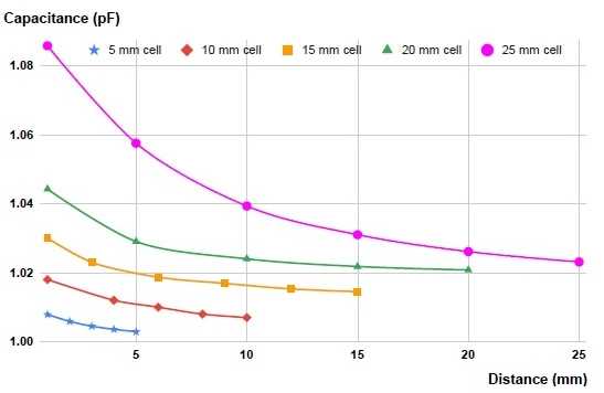
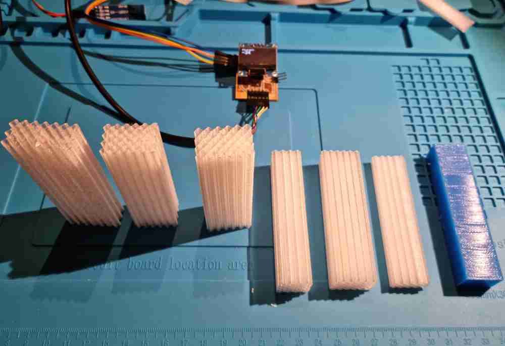
Now that i´ve got my step response, I made some test with the flexible 3D printed material in order to obtain the force/pressure values needed as you can check below.
TESTING MATERIALS FOR THE FORCE/PRESSURE SENSORING with the step response:
At this stage/phase of my final project development, i´m going slower than expected, but on the other hand i´m taking my time to learn, understand and most important, trying to design a device that can have a clinical utility for grip strenght measurement follow-up. I´m definetely going to run out of time, but i´ll try to learn and to make the best final project possible. Until now, i´ve got my grip nearly 100% designed, as it needs to have the flexible material defined for the strenght measurement, so, for the next step, my goal is going to be as follows:
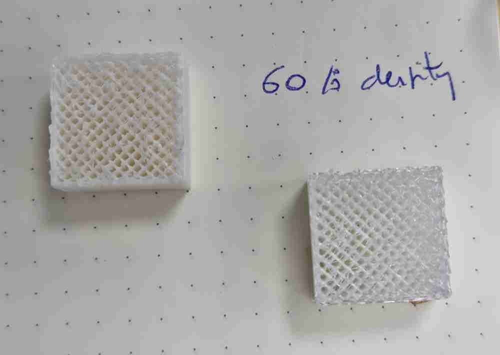
AIM: To test all the flexible materials made before (in the CAD desing) with 92A TPU Filament, by using them with my step response to see which parameters adjust better to our needs:
So, the tests made were:
| DESIGN PARAMETERS (size, width, space) | Nº OF ROWS AND COLUMNS | RESULTS |
| 2,5x0,7x2,55mm. | 6x4. | Stiff ++++. |
| 3,7x0,4x4,2mm. | 4x4. | Soft ++. |
| 3,2x0,5x4mm. | 6x4. | Stiff ++. |
| 3,4x0,5x4,4mm. | 6x4. | Stiff +. |
| 3,5x0,4x4,5mm. | 6x4. | Optimal flexibility. |
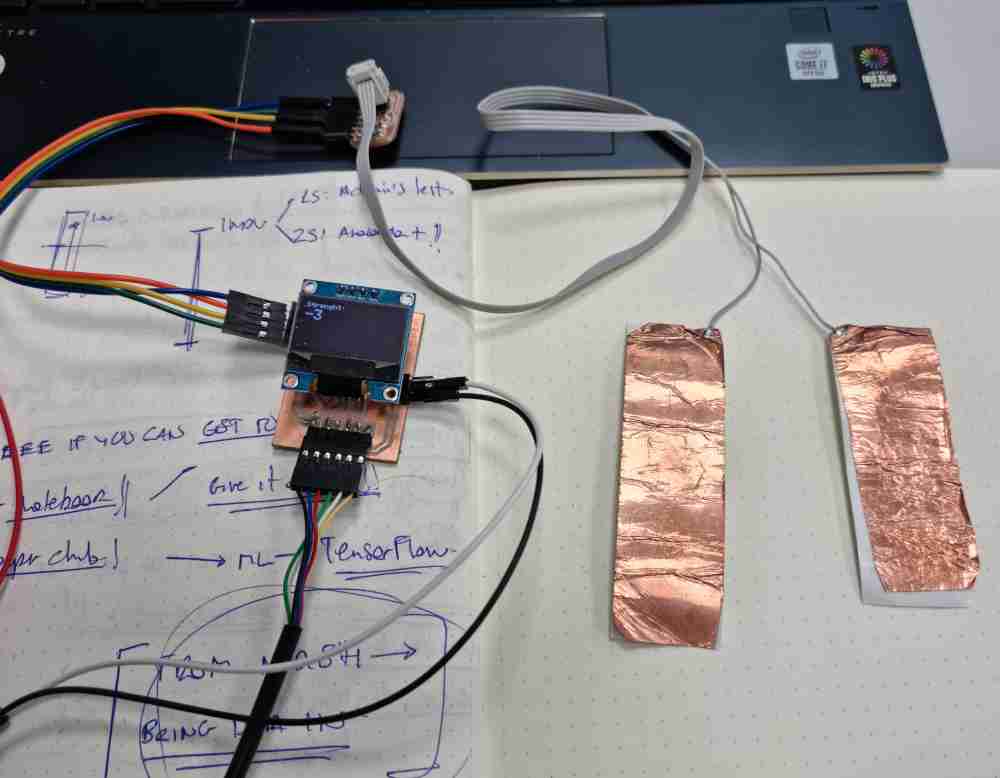
Down below, you can see how I tested this materials with the step response. In this case, I used "rigid" pcb plates as electrodes, and vinylcopper too.
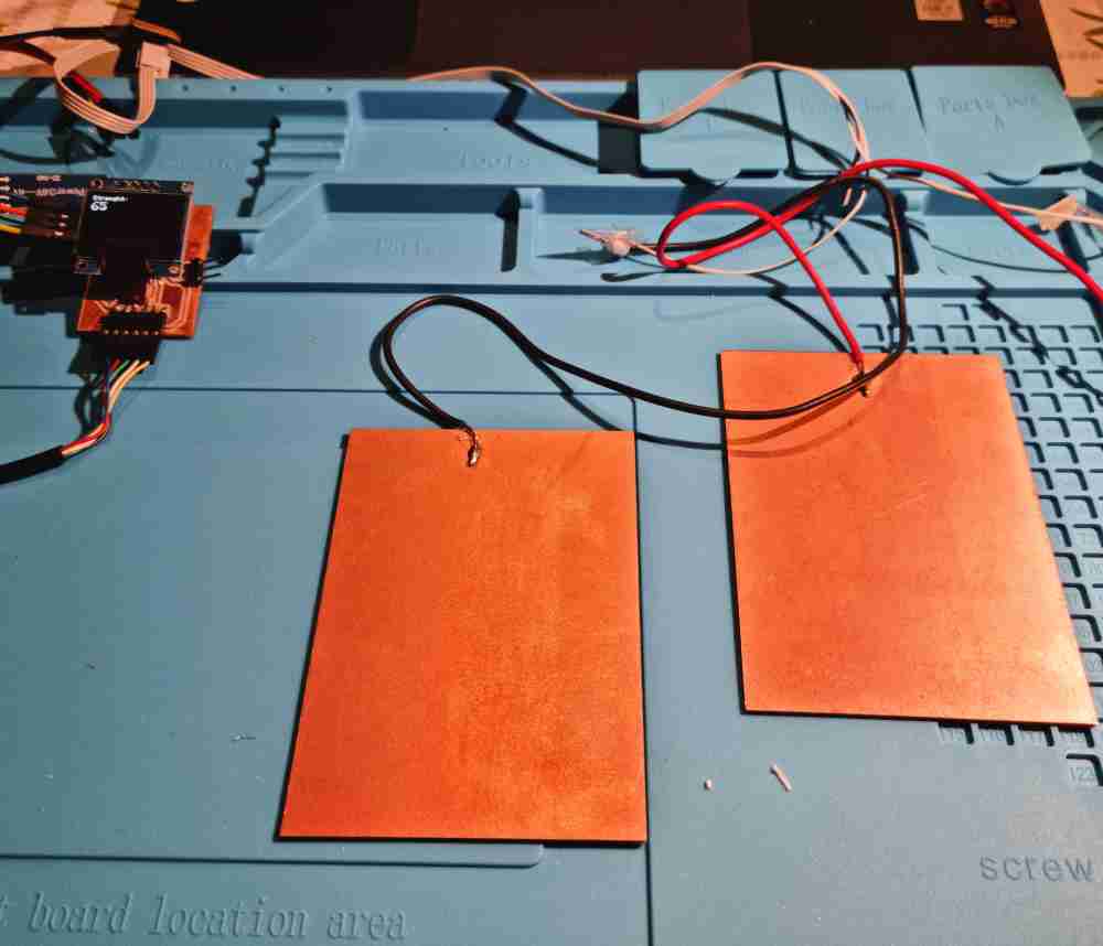 rigid pcb electrodes
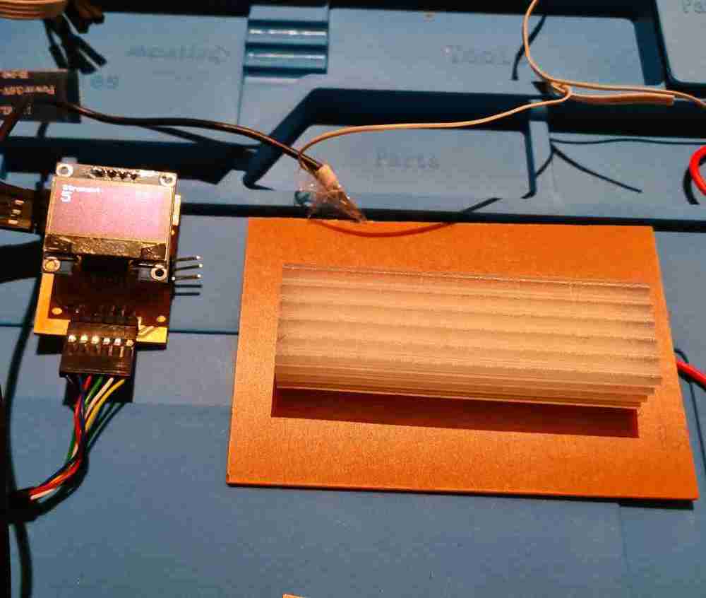
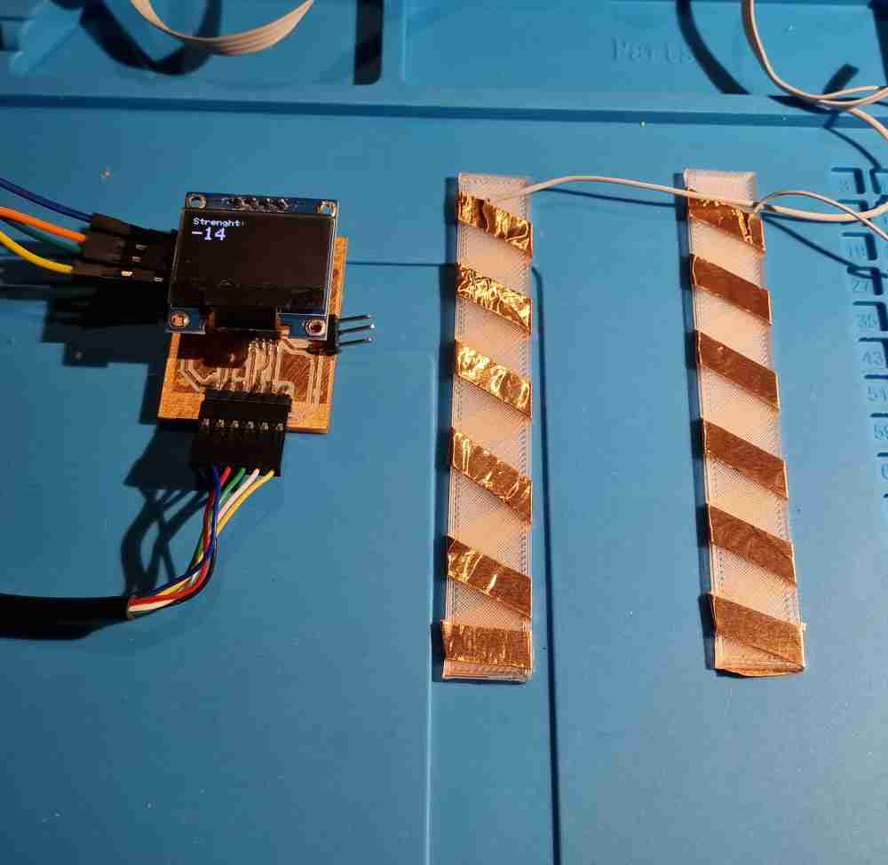 Vinyl copper electrodes
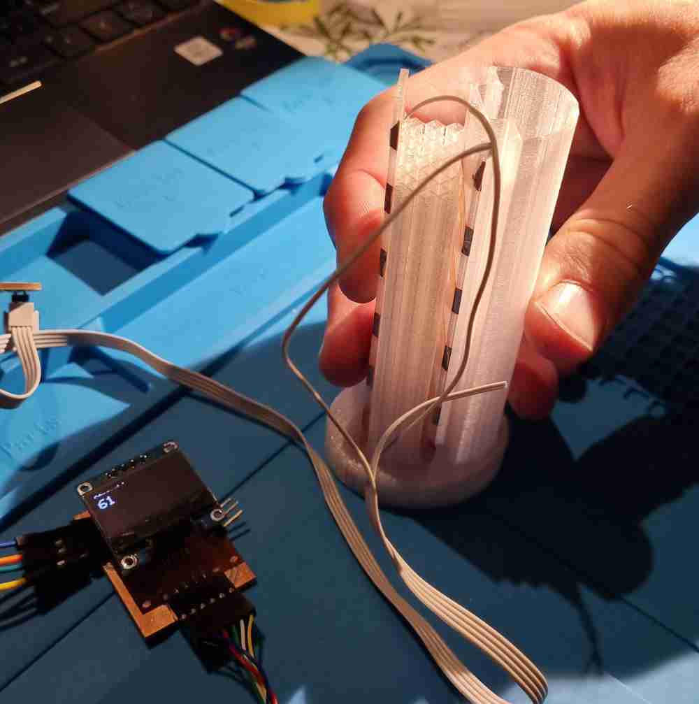
 All the materials tested
Here you can check how it works using two pcb(FR) as electrodes, and the different "resistance" response of the flexible material to pressure, being the material ordered from more to less flexible:
Finally, I obtained the desired "resistance" and flexibility for the inner structure made with flexible TPU, and now i´m ready to develop my final desing as í´ve finished iterating and i´m running out of time!
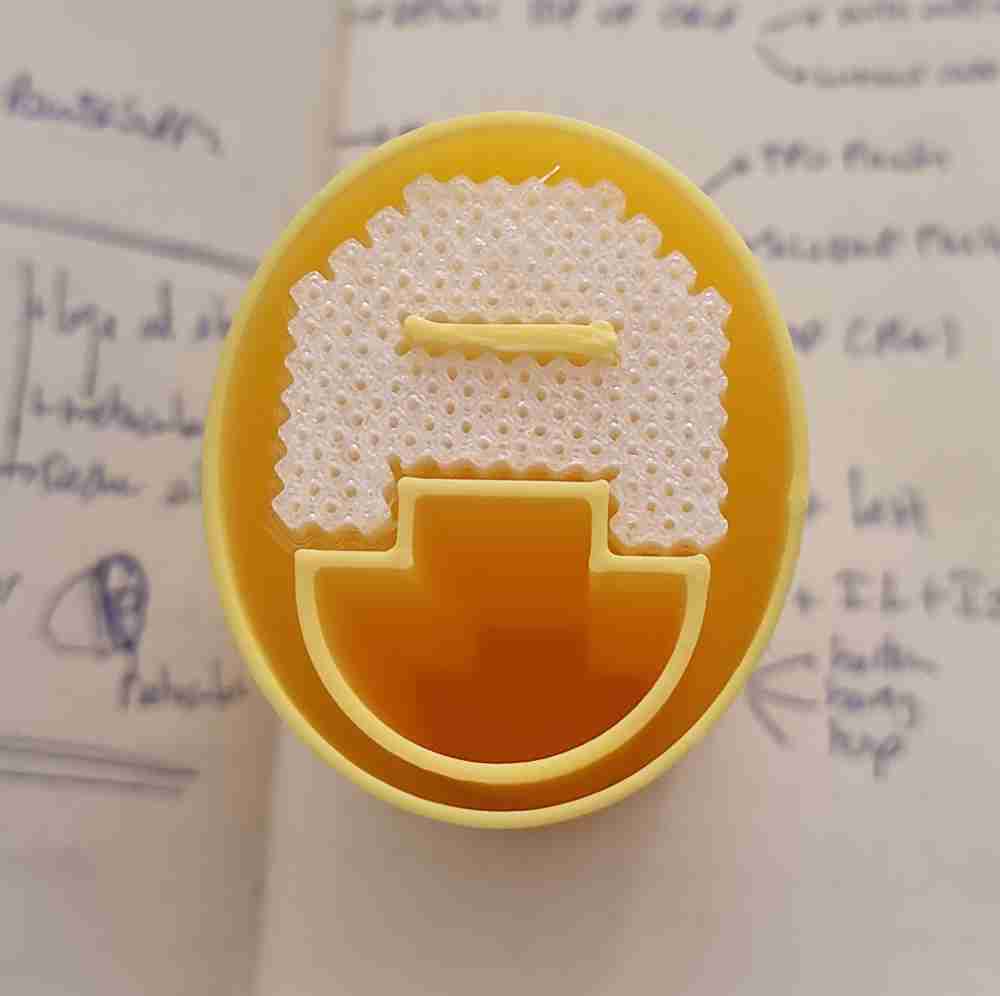
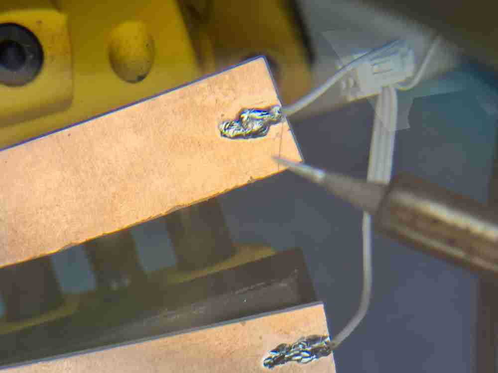 pcb FR1 electrodes
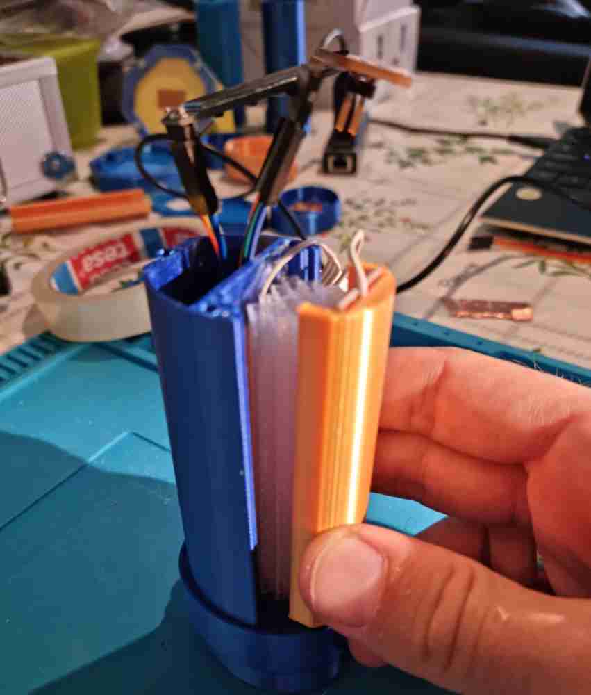
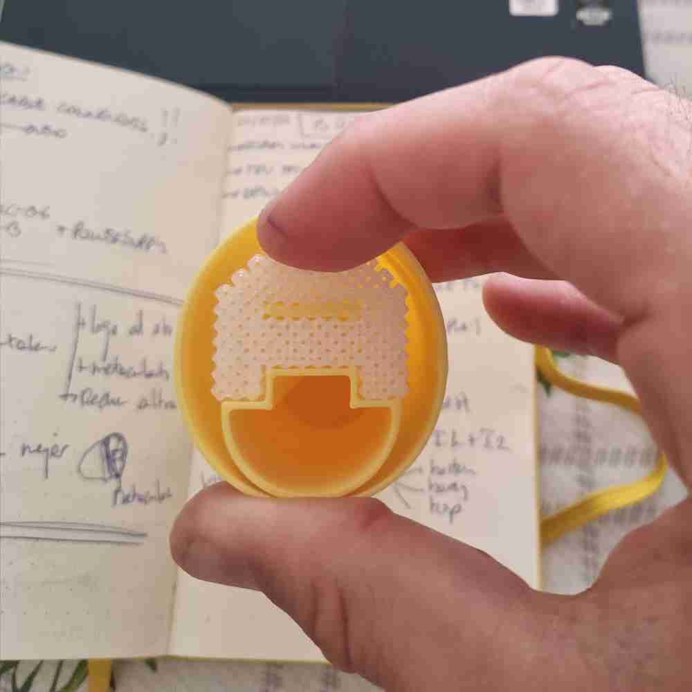
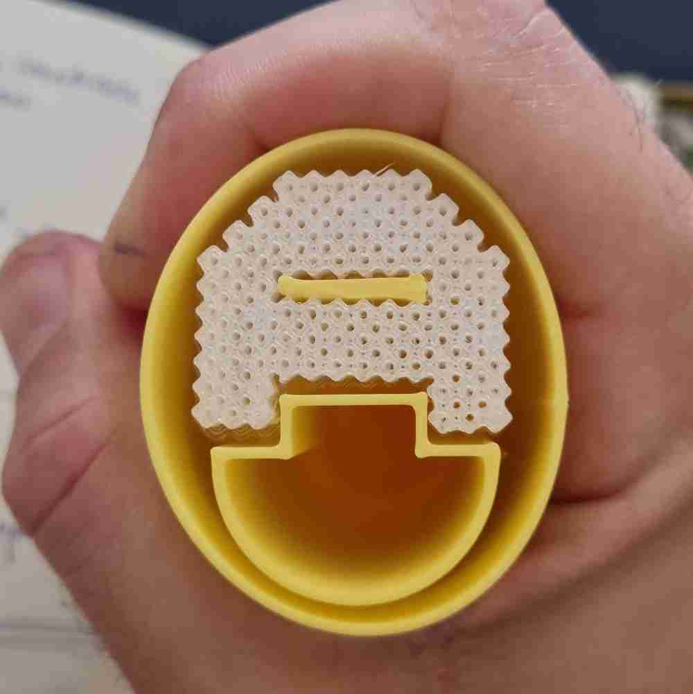
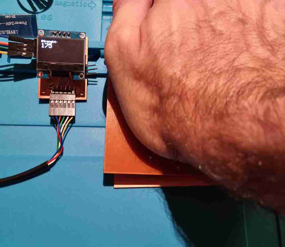
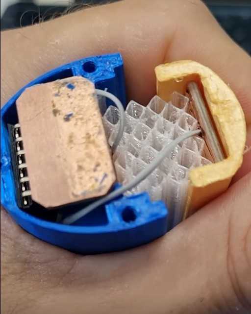 final step response assembled
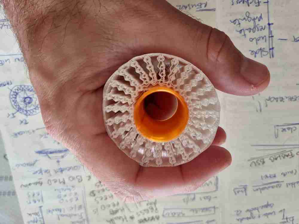
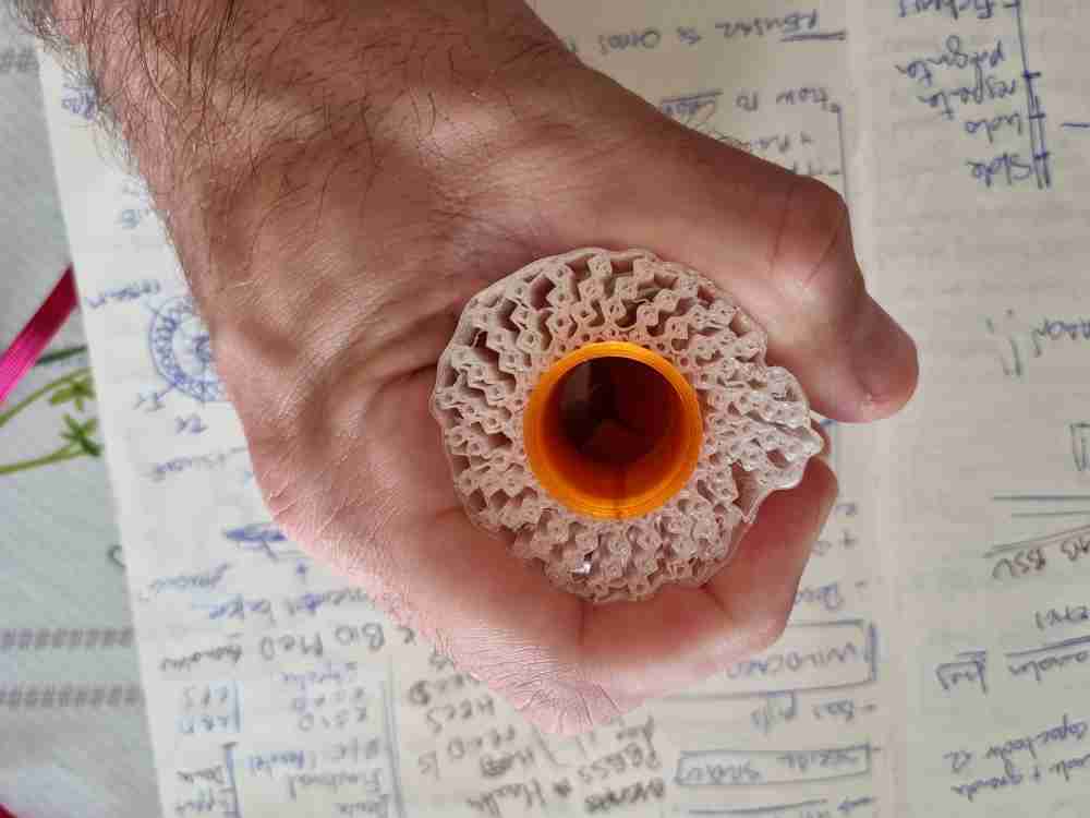
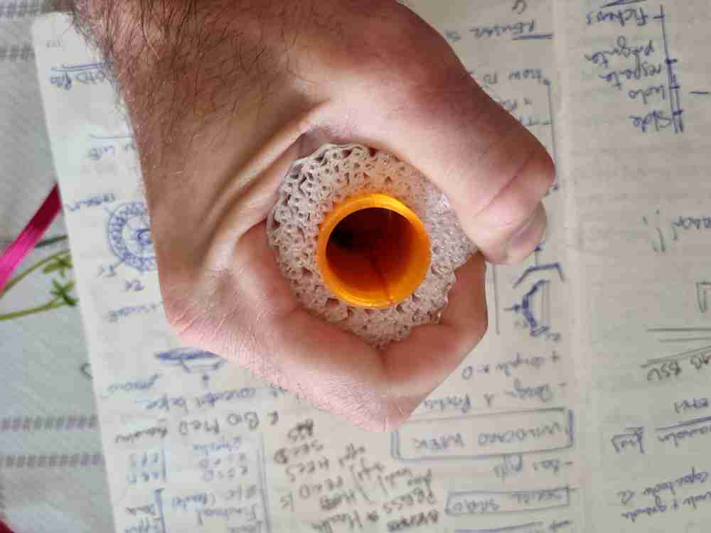
I had the best results soldering two of the the bus connector cables to the FR1 "cutted to size" electrodes, as they give a more stable measurements. Here above you can see an image of both electrodes with the TPU material in between and a 3D printed front structure (orange design) that will be where the pressure will be done. This structure will be surrounded by the silicone, giving a more comfortable grip.
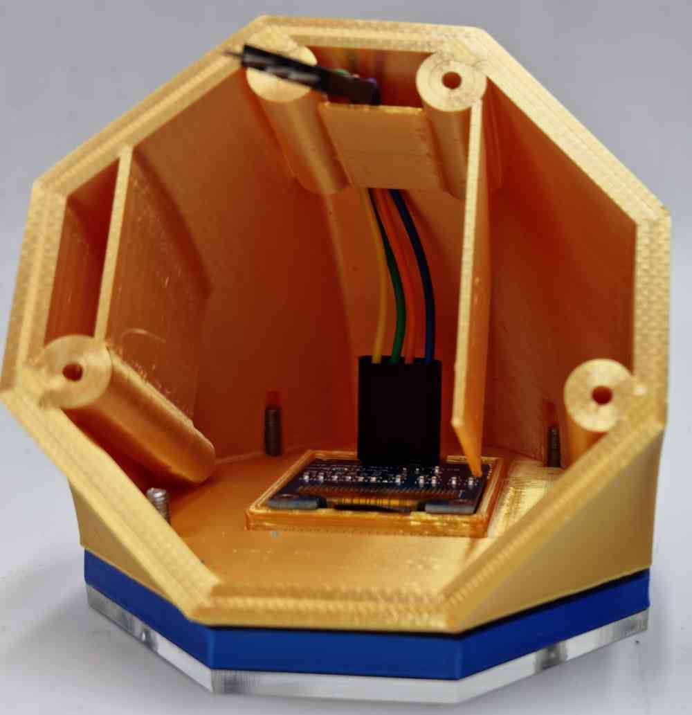
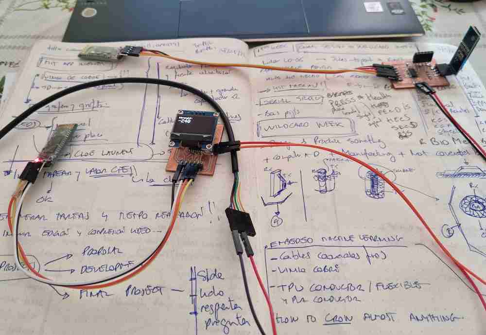
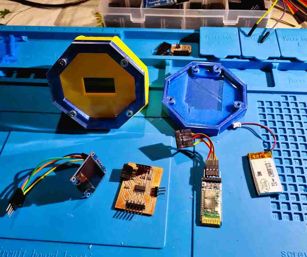
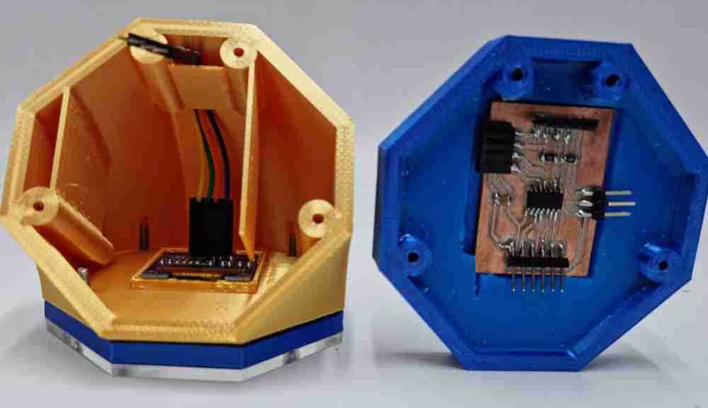
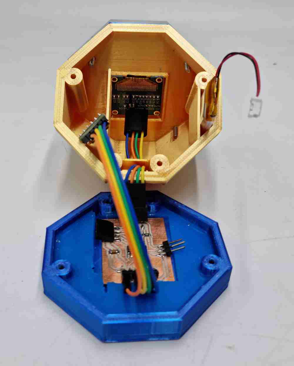
ELECTRONICS DESIGN
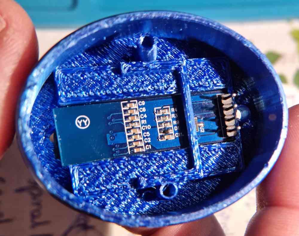
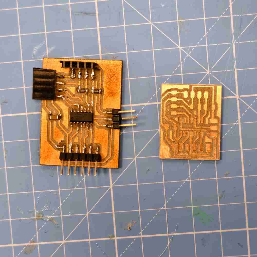
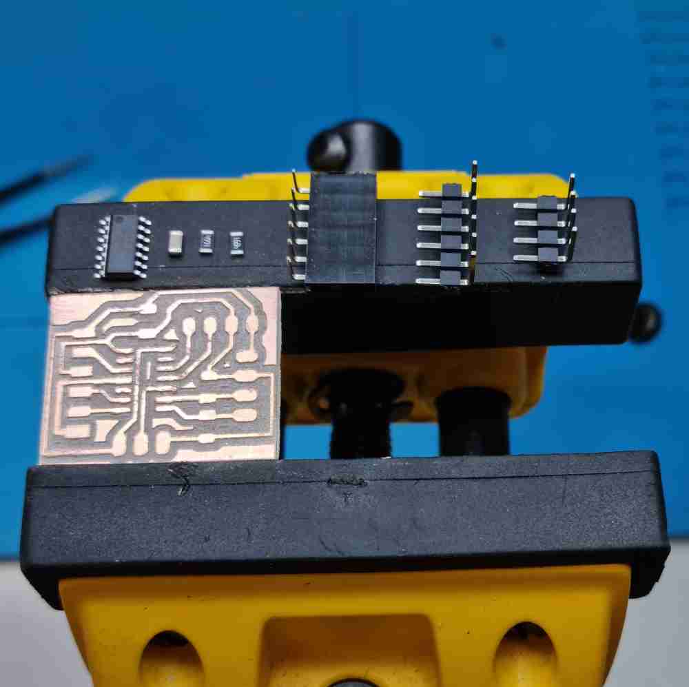
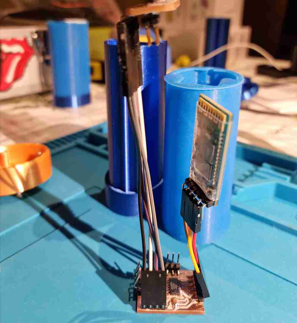
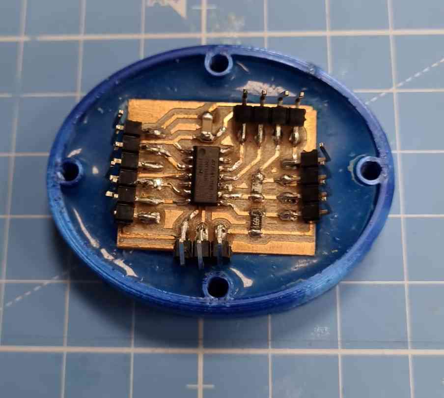
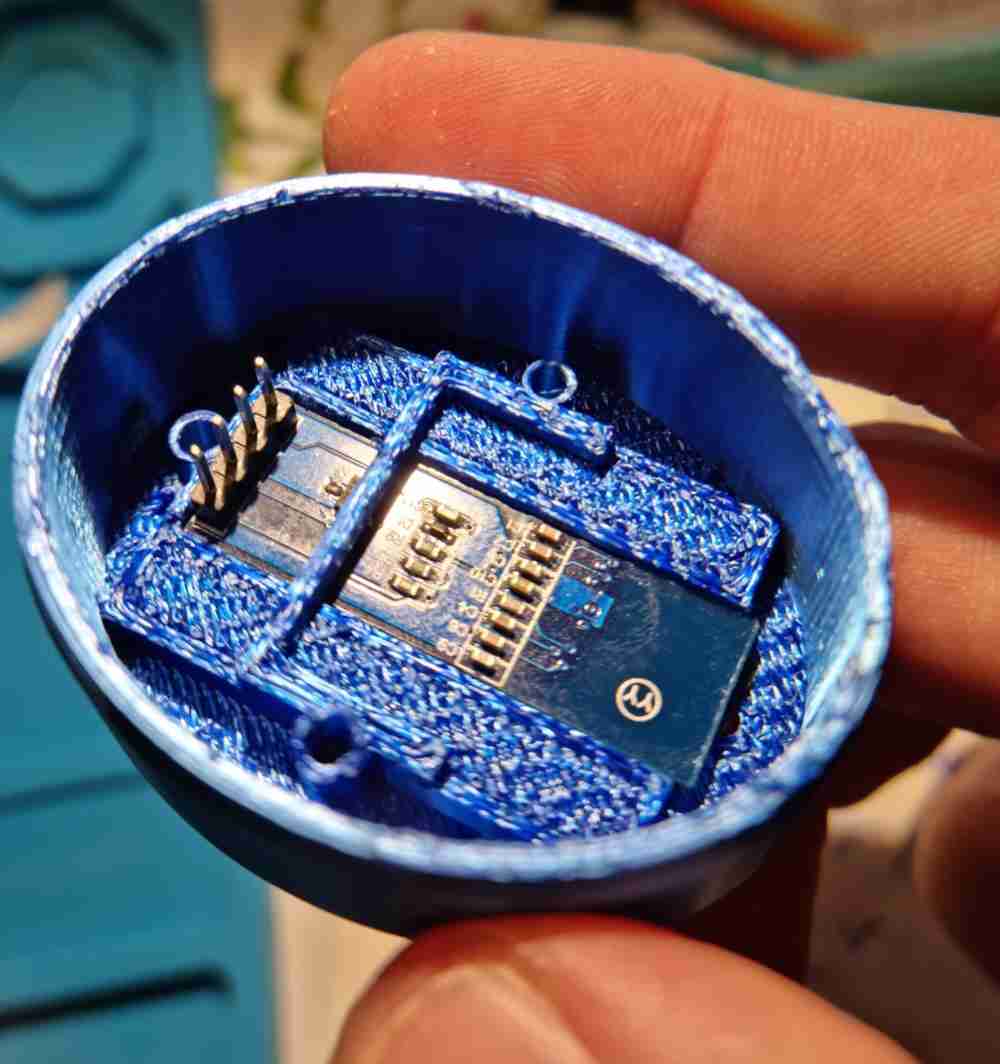
As explained above, I did a specific pcb board with an ATtiny1614 to control my step response, Input devices week, WEEK 12, visualizing data from an Oled module display and sending information via bluetooth. Even do that board works, it´s too big to fit my grip design, so I had to reduce the size of my board, and set the pin connectors facing upwards to facilitate it´s connection with the different modules.
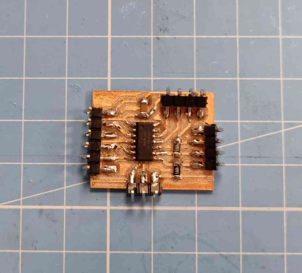
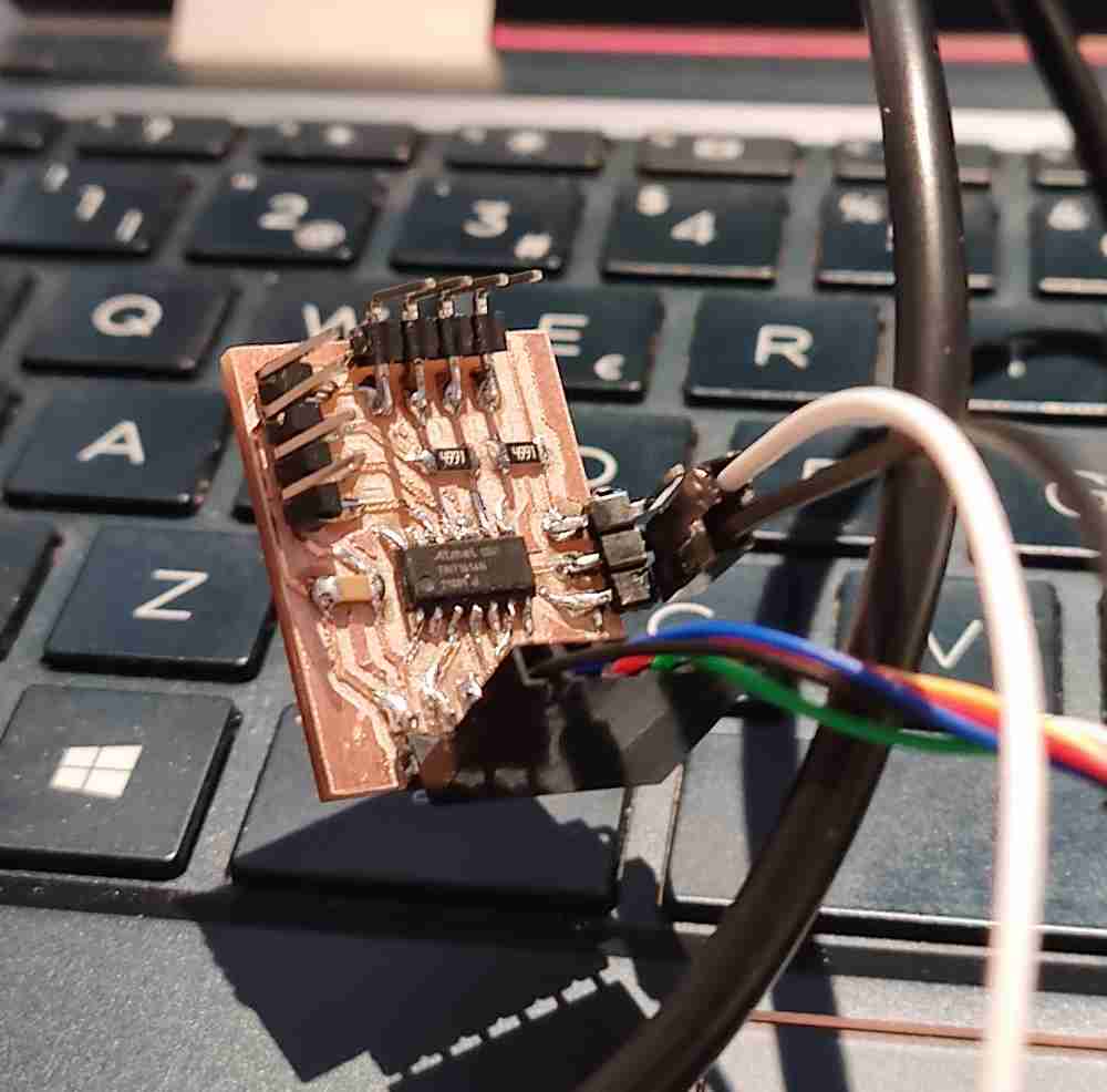
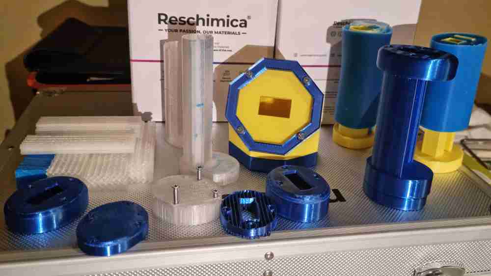
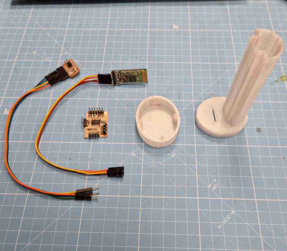
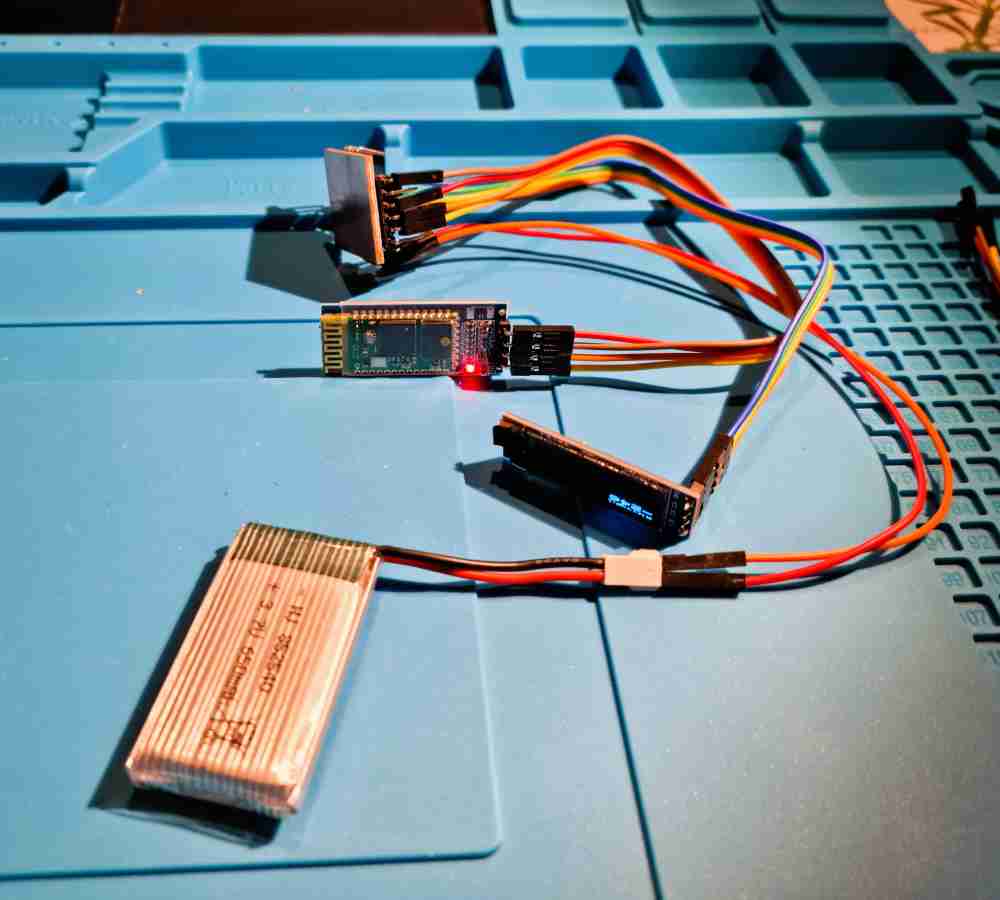
And here below, you can see all the electronic components needed for my first spiral, and it´s first test to see how they fit and to start preparing the nearby system integration, as therés a lot of cable cutting and adapting to do:
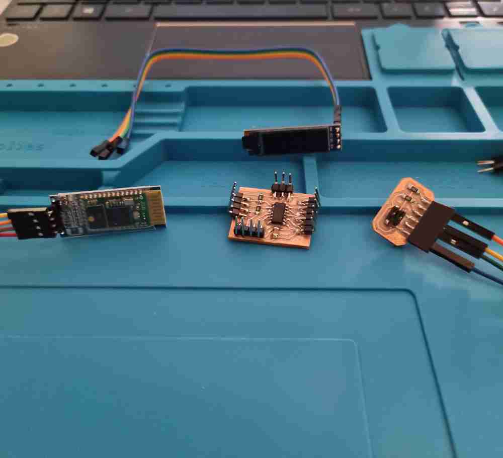
For my second spiral I used an identical ATtiny 1614 pcb board, that just differs as it has a different program. The differences are:
- First spiral board program: We only have the grip device board that will measure strenght from the step response, visualize it in the Oled modue display and send it, via HC-06 Bluetooth module, to a mobile phone or a computer.
- Second spiral board program: Now we have two boards. The grip board will do exactly the same as in the first spiral, but now it will only send the information via HC-05, master-slave, Bluetooth connection to the display module. The Display device board will receive this information and display it in the Oled module.
EMBEDDED PROGRAMMING AND NETWORKING
FIRST SPIRAL: INTERFACE DISPLAY: Interface and application program weeK (04 of May 2022)
As my goal is to visualize the strenght measurements, sent via bluetooth, in a mobile device or a computer, I initially reviewed the literature in order to obtain how many measures per second are needed for an optimal, and clinically useful value, and during how much time:
| ARTICLE/SENSOR | SETTINGS USED |
|---|---|
| Grip sensor 4256-E: | 10 measurements per second, in a minimum of 10 seconds. |
| Intrinsic hand strenght measurement, 2017: | No description, uses arduino board. |
| Distal phalanges strenght measurement, 2017: | 5 measurements per second, uses arduino board. |
| Weight load measurement on crutch: | 10 measurements per second. |
| Bachelors degree final thesis: | From 5 to 10 measurements per second. |
| Robotics, 2017. | Measuring between 3 and 10 seconds duration. |
The Gold Standard hand grip measurement protocol, indicates that to measure maximum grip strenght we need between 3 to 5 seconds of time measurement. From that time onwards, the maximum peak force decreases.
This information is very useful when displaying and storing the information for future analysis. So, for my first spiral I want to read the data in an friendly interface from any laptop, so I could work on this in interface and application programming assignment, week 14, were I used Processing to visualize my incoming grip strenght data.
Here´s a reminder of what I did that week, you can check the full assignment in the link above:
And once I understood how Processing worked, I started first with a wired (FTDi) connectionto my previously made, in input devices assignment, step response and followed with a wireless bluetooth HC-06 connection. To achieve it, I used Adrián´s Processing sketch for visualizing the step response data (Thank´s Adrián!), in his interface assignment. It really doesn´t need much modification due to the fact that in the Processing code you don´t declare the output variable, you just "call" the serial port from where you want to recieve the data, check the serial port number and the baudrate used.
 step response.
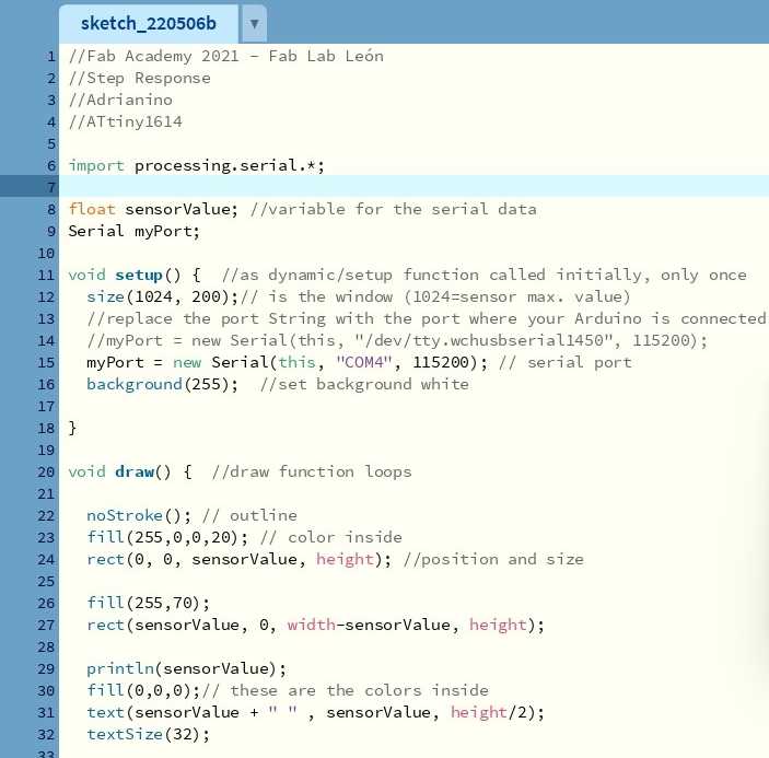 Adrián´s sketch.
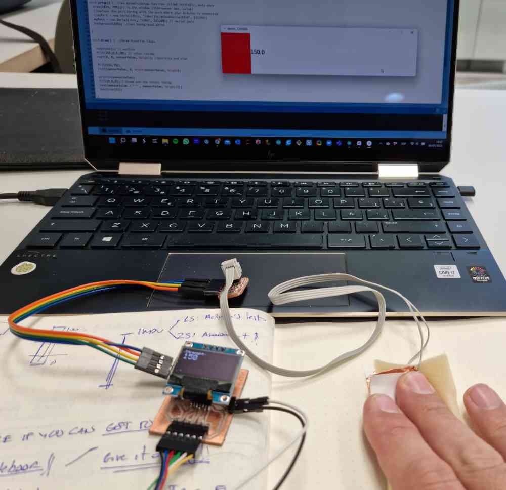 FTDI measuring.
Here you can check a video:
As for the electronics, for now it´s been great to apply in the final project development what i´ve learned in the previous weeks. It definetely helps me to progress faster and most important, to debug all issues encountered! As we can see in the next step, when I worked for the first time how to send information from an HC-05 to another HC-05 via master-slave connection.
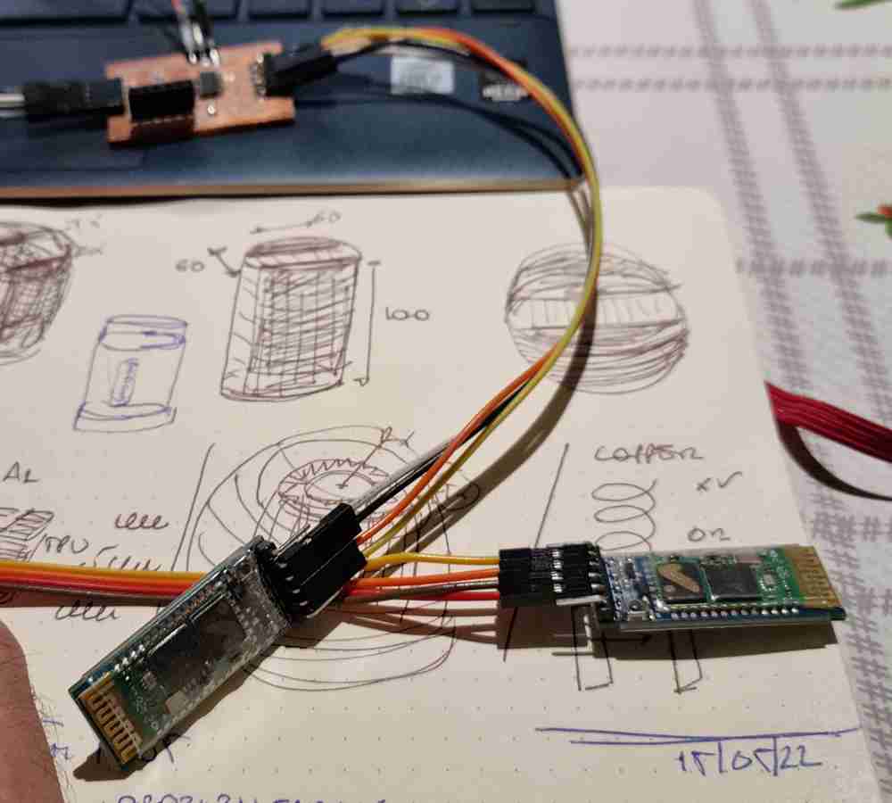
SECOND SPIRAL: NETWORKING: HC-05 - HC-05 Bluetooth connection
As the previous electronics weeks, I also used the Bluetooth connection made in week 13 between the step response and the laptop first, and mobile phone secondly, but in this case, as I also wanted to connect two HC-05 bluetooth modules in a master-slave connection.
To achieve it I followed some tutorials, Master-Slave connection that helped me to, understand what the master and slave concept means with the HC-05 Bluetooth module.
In order to pair both modules, I did as follows:
| First we need to configure both modules: Switch to AT command mode by pressing the button when powering the Bluetooth module. You will know that it´s properly connected as the led light will flash every two seconds. |
| Upload an empty sketch to the board. |
| Check your baudrate to ensure proper connection and communication with arduino IDE serial monitor, and connect to your board: In my case, baudrate = 38400. |
| Open Arduino IDE serial monitor and use the following codes when needed:. |
| AT+ADDR?= Module address// AT+ROLE?= 0 Slave, 1 Master. // AT+CMODE?= 0 Connected to one, 1 Connected to any. Now we have to change the HC-05 master and slave settings as wished. |
| AT+ROLE= 1 or O // AT+CMODE= O or 1 // AT+BIND= HC05 Slave address = to bind master and slave connection. |
 step response.
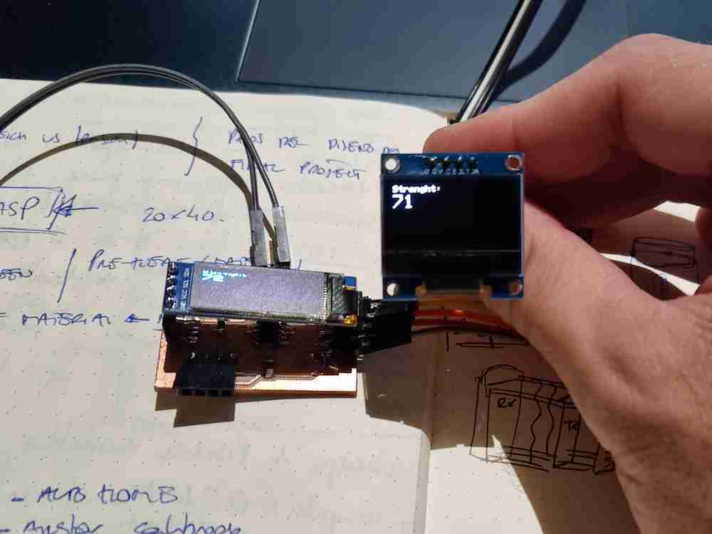 Adrián´s sketch.
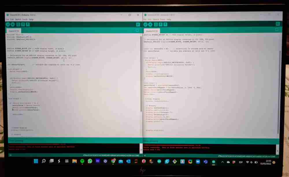 FTDI measuring.
Below are the arduino codes for the master and slave program, each one of them programmed in an ATtiny 1614 as shown before:
You can access the files in the FINAL PROJECT module.
Here you can check some videos of how it went. The first one shows the first pairing tests, and the second one is showing what the display module shows, above the real value measured and below the maximum measurement registered, that changes everytime the value increases.
For the first spiral, the grip device will send information to any mobile phone or computer via HC-06 Bluetooth Module, and for the second spiral my intention is that the information is sent from the grip device only to the module display specifically. This spiral is completely achieved, and works perfectly, now for a future spiral my goal will be to store, via SD card, the information recieved in the display module.
Applications and implications
Finally, I was also able to apply to the final project, before the system integration, the last two assigments. The work made in applications and implications, assignment, WEEK 16, helped me to prepare and clarify my time management and the steps I had to take to achieve a successful system integration of my final project.
Invention, Intellectual property and incomes
The final work done in the Invention, Intellectual property and incomes, assignment, WEEK 17 really helped me to focus on the posibilities regarding what I would like to do with this project once Fab academy finishes. You can check what license I chose ant the bottom of the left bar menu of every web page of my documentation. I have to admit that I hadn´t thought much about if before, so a really useful week for me.
SYSTEM INTEGRATION
This final section needs special attention. I know that everybody told us that system integration is tricky and takes time, even Neil reminded us that sometimes 20% of the work (system integration) can take up to 80% of the time. Well, fortunatelly it wasn´t so drastic, but for sure it was hard. Specially when you haven´t had this experience before, well, to be honest, the first experience was the machine week.
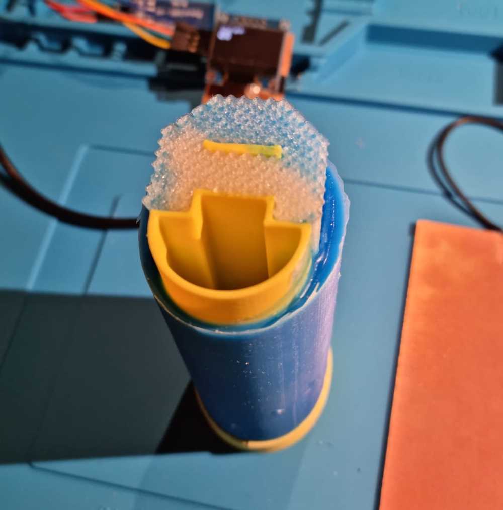
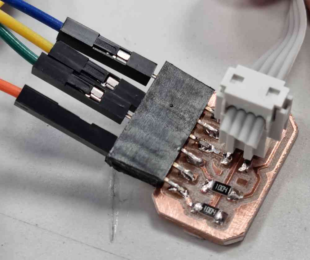
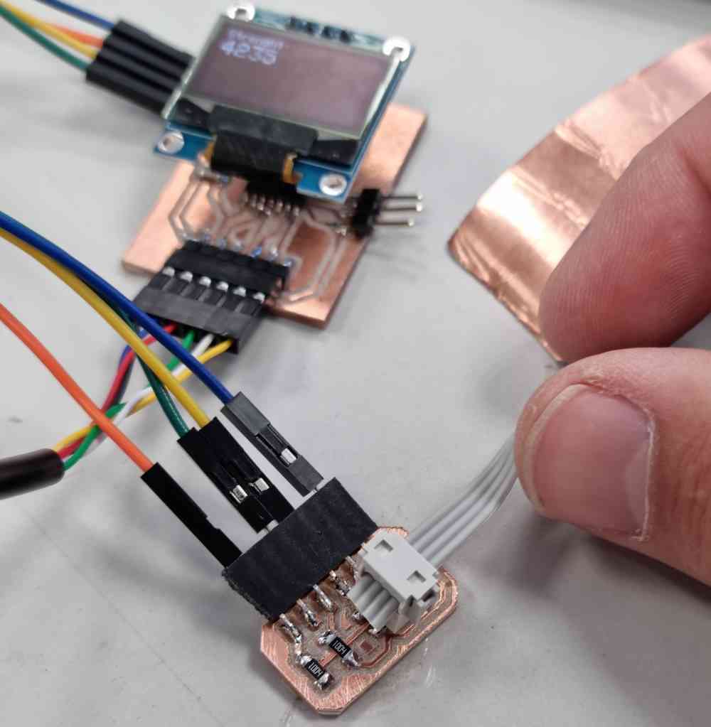
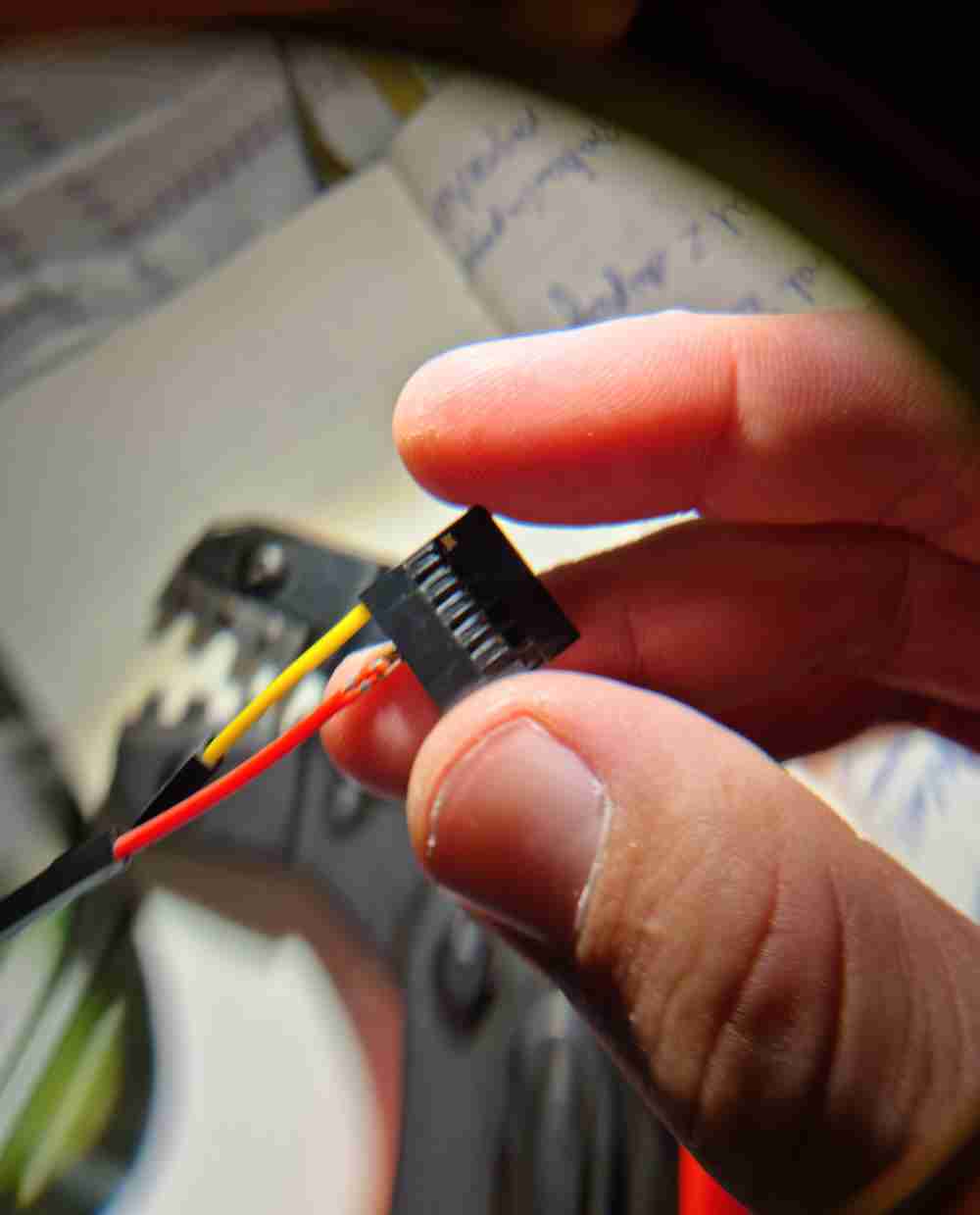
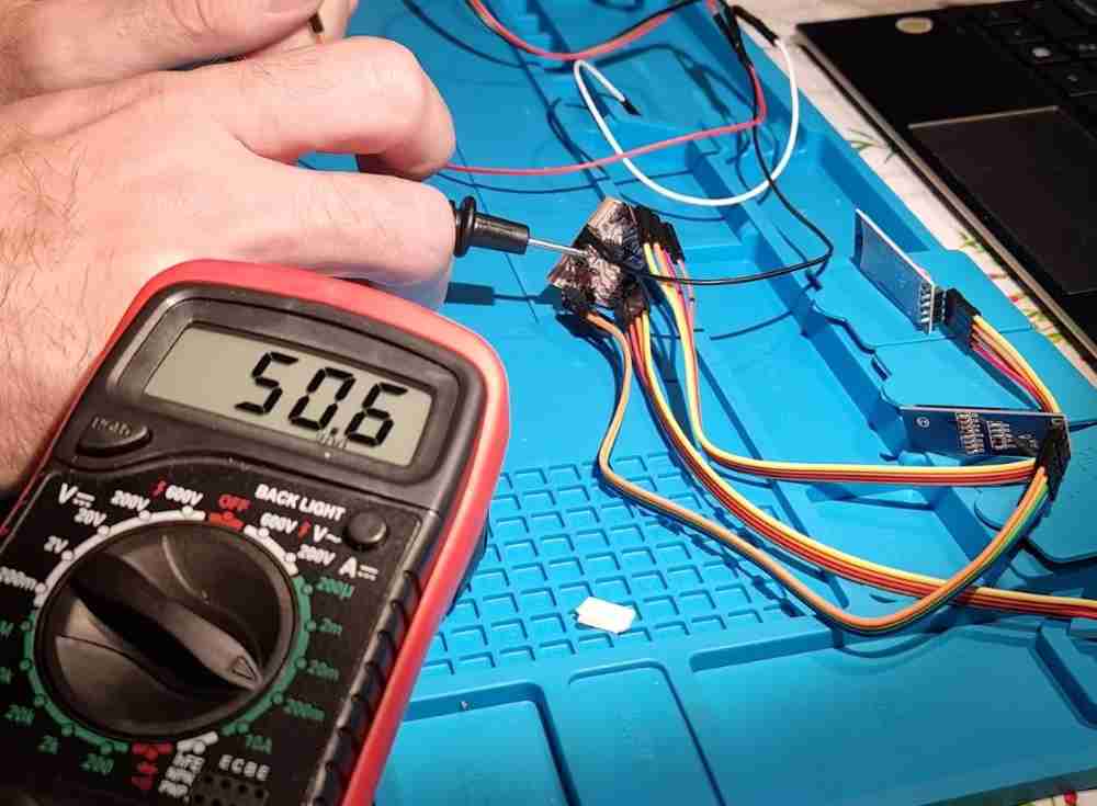
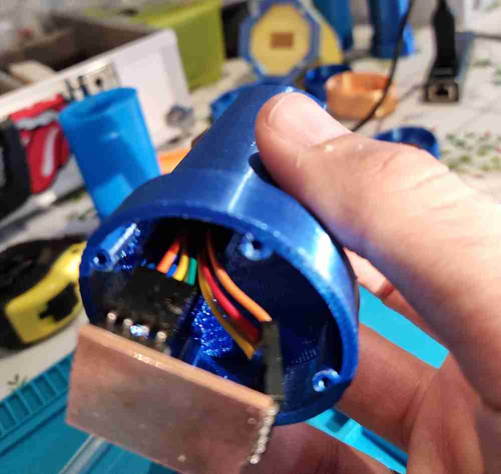
In my case, the most relevant part was to make all the components fit in a small design (grip design), as they all worked perfectly outside the grip structure. So my hardest steps were at first to prepare all the wiring in order to suit the final project design. This is were I learned that a crimping tool is mandatory to get the work done properly.
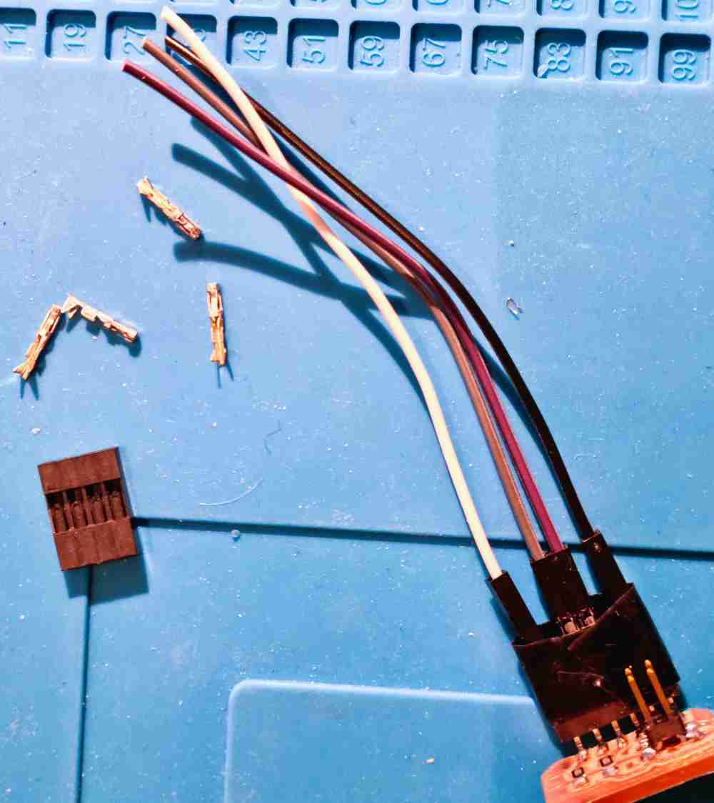
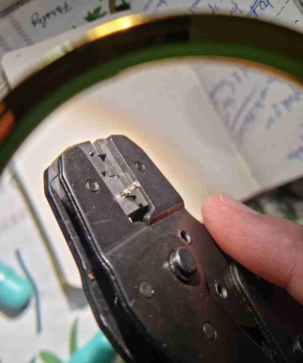 Crimping
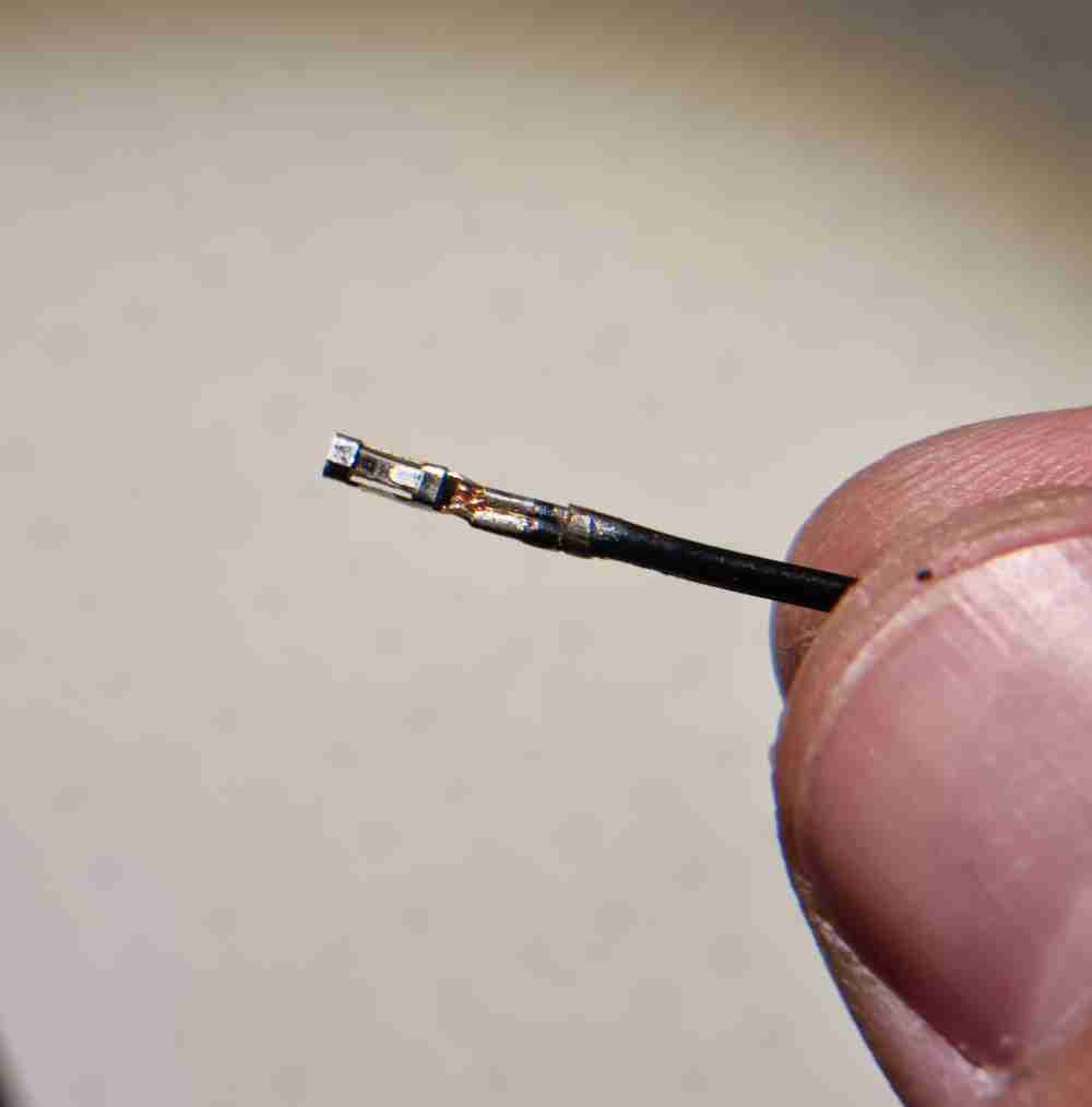
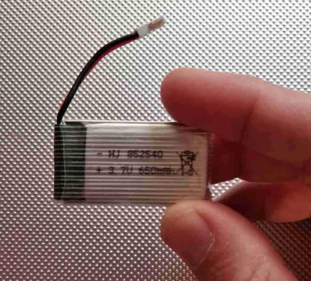
Another "new experience" I encountered while doing the system integration was how was I going to power it?. Finally, after hearing all the advices from my local instructor and the Regional Review I opted for lithium ion 3.7V rechargeable batteries. First I measured the power consumption of my electronics, which resulted in a maximum of 50mAh. So, finally I got a pair of 650mAh batteries that had the perfect size to fit in the grip design and in the display module, and gave an autonomy over 4 hours, which is more than enough for this spirals.
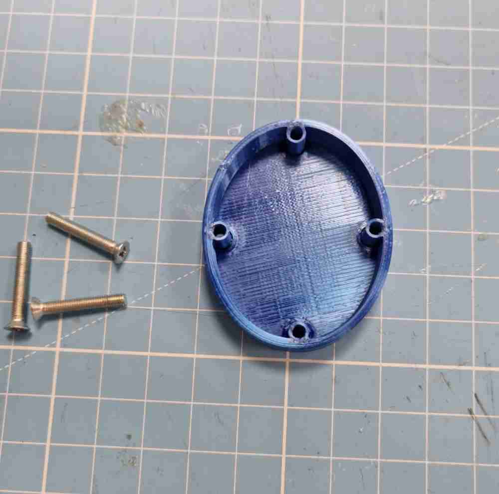
And finally, to assemble it all, I used 25mm long, 3mm diameter screws, and here below you can see how the final assembly went:
SPIRAL 1: 3D printing grip, silicone cover, step response, and electronics:
Videos of the step response system integration:
SPIRAL 2 SYSTEM INTEGRATION: 3D display module, acrylic screen, nd electronics:
And here´s how it looks once it´s completely assembled:
Testing it after assembly:
Finally, you can see the final testing in the FINAL PROJECT video.
WHAT HAS BEEN COMPLETED, AND WHAT TASKS REMAIN?
As you´ve been able to read during my project development journey, I managed to fully complete spiral 1 and 2, in time. So. I couldn´t be happier. To be honest, I would have been extremly happy if I didn´t manage to make it.. the process alone and all the learning has been worth it. As Neil says, this is just the beginning, and we will need a couple of years to sink it all in.. so i´ve got plenty of time. My next steps are going to be to improve my design, and add an SD card to save and register the measured data. At the same time, I want to clinically validate the measurement through a research project and test it in a adequate sample of subjects. So, wish me luck!
WHAT WENT WRONG AND LESSONS LEARNED
As it could not be otherwise, there were mistakes, errors, and improvements during the development of my final project. Here´s a list of the most relevant problems and lesson learned, some of them and others have already been mentioned during the project development:
| PROCEDURE | Lesson learned and how we dealed with issues and problems |
|---|---|
| 3D printing errors | I had to re-design my CAD files a few times regarding size and inner structure designs. At first it wasn´t rigid enough so I had to increase infill % and walls width |
| TPU testing | More than mistakes, it was the multiple setting testing until I printed TPU properly. I learned that direct extruding 3D printers are way much reliable to print flexible filament than those with bowden. Being capable of changing the "resistance" to pressure, it makes it the perfect material to be placed between the electrodes of the step response. |
| SILICONE Testing | As Neil suggested me when I got chosen in the random generator, silicone insert molding could be a good option. So I tested and learned that silicone is not a good material to be subjected to the grip force pressure, but It is an excelent material to give a comfortable external layer, that also contains the flexible TPU. |
| STEP RESPONSE making and testing | I designed my own step response following Adrián´s and Neil´s suggestions adapted to my CAD design and tested several materials to work as the electrodes. standard foam is too "soft" and hasn´t got the flexibility properties needed, Velostat won´t work due to hysteresis and copper vynil, even do it´s more adaptable, is not the best option as it deforms easily. The best "electrodes" are FR1 pcb cut to size, with copper only on one side as they give a stable measure, much less affected by electromagnetic changes. |
| The importance of good screened cable wiring and electrode mapping. | I learned how important is to use screened cables and to do do a good system integration in order to avoid interferences that can change your measurements. I also learned how important it is to map both your "electrodes" properly to help get the most reliable and stable value as possible in the step response. |
| How important it is to use Crimping tools | Probably the system integration was the most challenging task of all Fab academy. I learned the hard way how important is to adjust cables needed to it´s right lenght, and how indispensable it is to use crimping tools to ensure correct connections. It´s mandatory! |
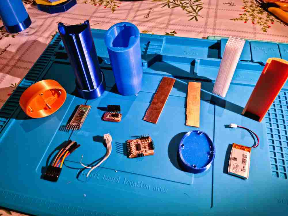
| Have ready two of everything | In one of Neil´s classes he suggested that we had to be prepared for everything, and suddenly I realized that I "only" had a final step response and pcb board that was valid for my final designs measures, so I created a couple of "extra" step response and boards programmed and prepared to use just in case, and damn I´m happy I did it. The day before the final presentation, the step response broke accidentally, and I just had to replace it with one of the spare ones! |
| Powering my device | As this is the first time I "build" something, there were a lot of things I didn´t think about at first, as how was I going to "power" my design due to the limited space and size of my grip device. So, I had to test different alternatives and finally opted for Lithium ion 3.7V rechargeable 650mAh batteries, after measuring the total consumption of my device. This option works great but I had to let go of my 5.V neo pixels for the moment. |
Back to top.
Get in touch

This work is licensed under a Creative Commons Attribution-NonCommercial-ShareAlike 4.0 International License.