In this section we list the activities to be solved in the following table:
| Checklist | Estatus |
|---|---|
| Documented the machine building process to the group page. | Finished |
| Documented your individual contribution to this project on your own website | Finished |
| Linked to the group page from your individual page as well as from group page to your individual pages | Finished |
| Shown how your team planned and executed the project (Group page) | Finished |
| Described problems and how the team solved them (Group page) | Finished |
| Listed future development opportunities for this project (Group page) | Finished |
| Included your design files (Group page) | Finished |
| Optionally included an aprox. 1 min video (1920x1080 HTML5 MP4) + slide (1920x1080 PNG) (Group page) | Finished |
For this assignment he decided on a Maslow CNC.
A Maslow CNC, is a vertical cutting equipment, noted for its low cost and its open-source feature. The Maslow CNC project was created in 2016 by Bar Smith, Hannah Teagle and Tom Beckett.
 Maslow is a large (4'x8') CNC cutting machine designed to let you cut big, useful things out of wood and other flat materials.
In the following video you will see how a CNC Maslow works.
- Design a machine that includes mechanism + actuation + automation + application
- Build the mechanical parts and operate it manually.
- Document the group project
For the development of this OPEN SOURCE type project, a planning consisting of 4 stages was made:
For this assignment, tasks were planned and assigned as follows.
I detail my contribution in my individual assignment.
The Group Assignment page is at the following link: Maslow CNC.
- Document your individual contribution.
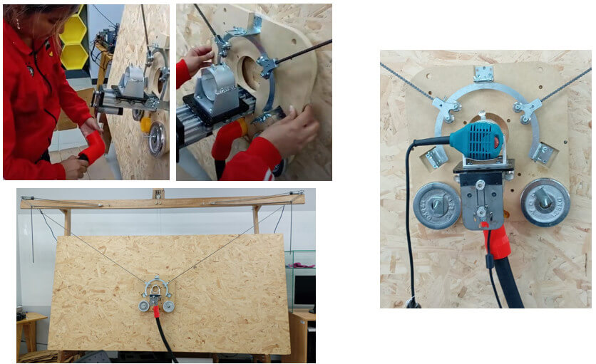
The sled will provide support and fixation to the shaft where the cutting tool will be placed. This piece allows the Maslow to function correctly. A successful sled construction will ensure that the router bit rests at the center point of the sled, ensuring that the bit will remain along its designated cutting line regardless of how the sled is rotated.
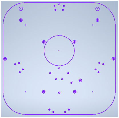
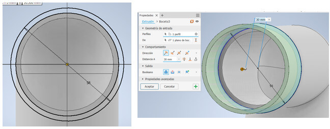
I will work on the design in Inventor. Draw a square of 400mm per side, the corners will be rounded using the "fillet" command by introducing an arc with radius = 80mm. Now we make the hole of approximately 54.9mm radius for the Z displacement axis, this is where the tool will move.
  The location of a tube for suction of waste will be considered, located at the bottom which will be supported by three bolts and I will also make holes for the axle support, as shown in the image.
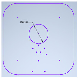 Now we will draw the holes for attaching the Maslow ring carriage, this ring allows the router bit to remain centered and undisturbed for a smooth cutting line.
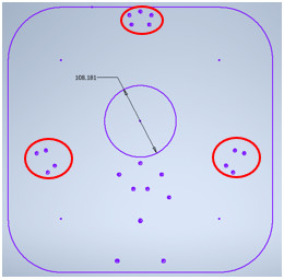 For better movement of the sled, a protective rubber will be placed, we will draw circles, located around the sled.
 Finally, the sled must be supported strongly with weights, which will go on both sides of the axle.
 All fixing holes are considered approximately 5mm, this is due to the diameter of the screws.
As I progressed I made some test cuts on the laser cutter to verify that the holes matched up. After I verified, I proceeded to make the cut on the cnc machine. I proceed to assemble the pieces of the sled but there is a small detail, the MDF is 18mm and the bolts are shorter and do not enter to the other side, so I must modify the design, a solution is to remove the material by about 15mm in the areas where the ring carriage, the waste suction tube and the axle support will go. So the final design is as shown.
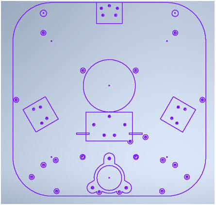 Once the final design is obtained, we download the file in dxf format, and then open it in the Rhino Cam software to obtain the Gcode and make the respective cut.
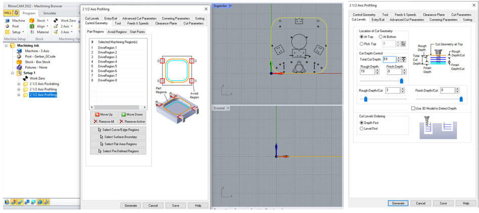
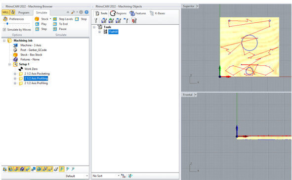
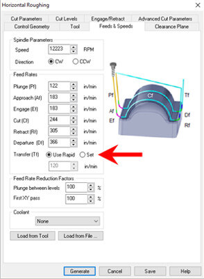
In this section we will follow the steps seen in the week 08 assignment on GCODE generation in Rhino CAM. Three processes will be carried out: material reduction (pocketing), an inside cut (profiling) and an outside cut (profiling).
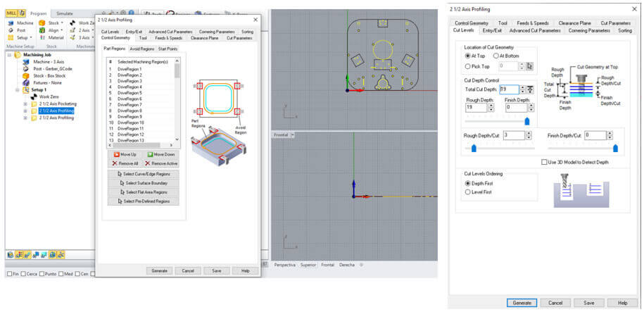
 I will work with a 3 mm diameter and 5 flute milling cutter.
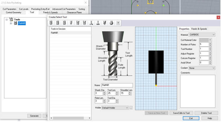 Here are some simulations of the process.
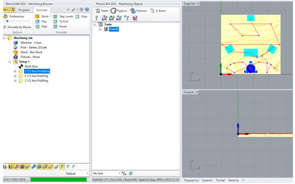

Similarly, here we will follow the steps seen in the assignment of week 08 in the “RichAuto CNC DSP A11S Controller” section. The final result allows a better fit of the pieces.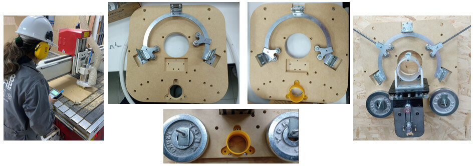
The suction tube will be used to attach a vacuum cleaner that will suck up the waste generated in the machining process. This suction tube consists of two parts, the base that will be attached to the sled and a 90° elbow to which the vacuum will be attached. This will be done with 3D printing.
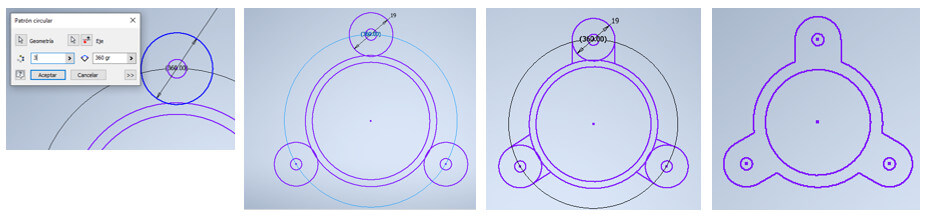
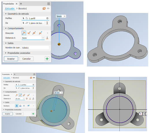
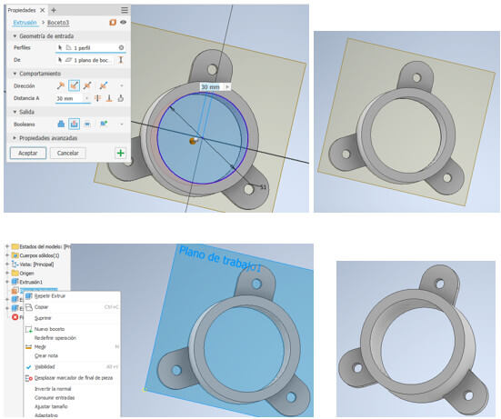
First we will make a circular base that will be held with three bolts, we will use the commands “circle”, “circular pattern”, “extrude” to create the base piece. Here are some images of the design.
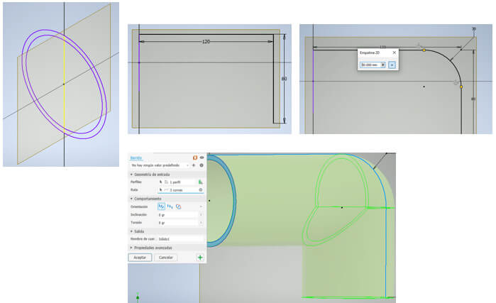
A tube will be placed on the base with a 90° bend. We will use the “Sweep” command. Here are some images of the design.
Once the design is finished, we export it in stl format, because this aspiration tube will be made with 3D printing.
In the Cura software, we open the stl file of the aspiration tube design, configure the printing parameters to obtain the GCODE and start printing the parts.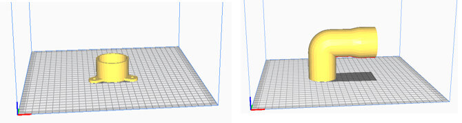 We download the files and take them to the 3D printers on a USB.
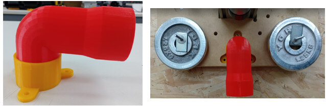
Final result, it turned out pretty good.
Maslow's electronic system consists of the following:
1. Keystudio Mega 2560 Microcontroller (Arduino Compatible) with USB Cable. It is the brain of the machine.
2. TLE5206 power control board: Maslow CNC motor controller shield. Aallows individual control of the motors.
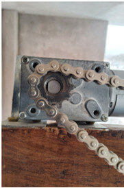
The TLE5206 power control board must be connected to the Keystudio Mega 2560 Microcontroller, taking care that all the pins are aligned because they could become twisted. 3. Three motor/encoder/gearbox units with their respective connecting cable: these motors are responsible for the movement of the cutting tool, the end motors allow movement in X and Y, the central motor in Z. The image shows the connection of the motors to the TLE5206 power control board.
 4. 12V DC 5A/110-250V AC power supply: It provides the voltage necessary for the operation of the motors and must be connected to the motor controller shield.
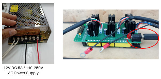 Finally, the USB cable from the Keystudio Mega 2560 Microcontroller is connected.
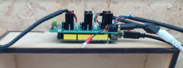 We energize the card, you can see that the green LED lights up.
After connecting the electronic components, it is necessary to install the appropriate firmware and drivers to connect to the Arduino. The good thing is that all the software for this machine is open source and we can obtain it for free. We can obtain the latest version of the firmware here. It is recommended to download the zip file of the latest firmware version.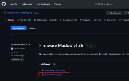 After extracting the files, open the firmware from the Arduino IDE by selecting cnc ctrl v1.ino.
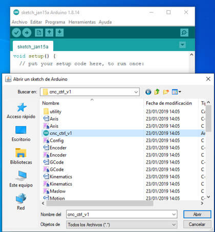
In tools choose the board and communication port. Now all that remains is to load the program and that's it.
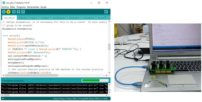
The difficulties were:
created with
Web Design Software .