//Olenka Od ar - Fab Academy 2023
//FAB-XIAO RP2040 "SOUND + LED STRIP"
//ARDUINO IDE
#include <Adafruit_NeoPixel.h>
int sensor = D8;
int val_sensor=0;
int conta=0;
int pulso_sal=0;
int Power = 11;
int PIN = D1;
#define NUMPIXELS 18
Adafruit_NeoPixel pixels(NUMPIXELS, PIN, NEO_GRB + NEO_KHZ800);
void setup() {
Serial.begin(9600);
pinMode(sensor, INPUT);
pinMode(PIN, OUTPUT);
pixels.begin();
pinMode(Power,OUTPUT);
digitalWrite(Power, HIGH);
}
void loop() {
while(true){
if(conta==0){
pregunta_sensor();
pixels.show();
pixels.clear();
pixels.setPixelColor(0, pixels.Color(0, 0, 0));
pixels.setPixelColor(1, pixels.Color(0, 0, 0));
pixels.setPixelColor(2, pixels.Color(0, 0, 0));
pixels.setPixelColor(3, pixels.Color(0, 0, 0));
pixels.setPixelColor(4, pixels.Color(0, 0, 0));
pixels.setPixelColor(5, pixels.Color(0, 0, 0));
pixels.setPixelColor(6, pixels.Color(0, 0, 0));
pixels.setPixelColor(7, pixels.Color(0, 0, 0));
delay(100);}
if(conta==1){
pregunta_sensor();
pixels.show();
pixels.clear();
pixels.setPixelColor(0, pixels.Color(255, 255, 255));
pixels.setPixelColor(1, pixels.Color(255, 255, 255));
pixels.setPixelColor(2, pixels.Color(255, 255, 255));
pixels.setPixelColor(3, pixels.Color(255, 255, 255));
pixels.setPixelColor(4, pixels.Color(255, 255, 255));
pixels.setPixelColor(5, pixels.Color(255, 255, 255));
pixels.setPixelColor(6, pixels.Color(255, 255, 255));
pixels.setPixelColor(7, pixels.Color(255, 255, 255));
delay(100);}
if(conta==2){//azul
pregunta_sensor();
pixels.show();
pixels.clear();
pixels.setPixelColor(0, pixels.Color(15, 25, 205));
pixels.setPixelColor(1, pixels.Color(15, 25, 205));
pixels.setPixelColor(2, pixels.Color(15, 25, 205));
pixels.setPixelColor(3, pixels.Color(15, 25, 205));
pixels.setPixelColor(4, pixels.Color(15, 25, 205));
pixels.setPixelColor(5, pixels.Color(15, 25, 205));
pixels.setPixelColor(6, pixels.Color(15, 25, 205));
pixels.setPixelColor(7, pixels.Color(15, 25, 205));
delay(200);}
if(conta==2){//rojo
pregunta_sensor();
pixels.show();
pixels.clear();
pixels.setPixelColor(0, pixels.Color(255, 0, 0));
pixels.setPixelColor(1, pixels.Color(255, 0, 0));
pixels.setPixelColor(2, pixels.Color(255, 0, 0));
pixels.setPixelColor(3, pixels.Color(255, 0, 0));
pixels.setPixelColor(4, pixels.Color(255, 0, 0));
pixels.setPixelColor(5, pixels.Color(255, 0, 0));
pixels.setPixelColor(6, pixels.Color(255, 0, 0));
pixels.setPixelColor(7, pixels.Color(255, 0, 0));
delay(200);
}
if(conta==2){//rojo
pregunta_sensor();
pixels.show();
pixels.clear();
pixels.setPixelColor(0, pixels.Color(255, 0, 0));
pixels.setPixelColor(1, pixels.Color(255, 0, 0));
pixels.setPixelColor(2, pixels.Color(255, 0, 0));
pixels.setPixelColor(3, pixels.Color(255, 0, 0));
pixels.setPixelColor(4, pixels.Color(255, 0, 0));
pixels.setPixelColor(5, pixels.Color(255, 0, 0));
pixels.setPixelColor(6, pixels.Color(255, 0, 0));
pixels.setPixelColor(7, pixels.Color(255, 0, 0));
delay(200);}
if(conta==2){//fucsia
pregunta_sensor();
pixels.show();
pixels.clear();
pixels.setPixelColor(0, pixels.Color(64, 0, 128));
pixels.setPixelColor(1, pixels.Color(64, 0, 128));
pixels.setPixelColor(2, pixels.Color(64, 0, 128));
pixels.setPixelColor(3, pixels.Color(64, 0, 128));
pixels.setPixelColor(4, pixels.Color(64, 0, 128));
pixels.setPixelColor(5, pixels.Color(64, 0, 128));
pixels.setPixelColor(6, pixels.Color(64, 0, 128));
pixels.setPixelColor(7, pixels.Color(64, 0, 128));
delay(200);
}
if(conta==2){//verde
pregunta_sensor();
pixels.show();
pixels.clear();
pixels.setPixelColor(0, pixels.Color(0, 255, 0));
pixels.setPixelColor(1, pixels.Color(0, 255, 0));
pixels.setPixelColor(2, pixels.Color(0, 255, 0));
pixels.setPixelColor(3, pixels.Color(0, 255, 0));
pixels.setPixelColor(4, pixels.Color(0, 255, 0));
pixels.setPixelColor(5, pixels.Color(0, 255, 0));
pixels.setPixelColor(6, pixels.Color(0, 255, 0));
pixels.setPixelColor(7, pixels.Color(0, 255, 0));
delay(200);
}
if(conta==2){//turquesa
pregunta_sensor();
pixels.show();
pixels.clear();
pixels.setPixelColor(0, pixels.Color(0, 162, 232));
pixels.setPixelColor(1, pixels.Color(0, 162, 232));
pixels.setPixelColor(2, pixels.Color(0, 162, 232));
pixels.setPixelColor(3, pixels.Color(0, 162, 232));
pixels.setPixelColor(4, pixels.Color(0, 162, 232));
pixels.setPixelColor(5, pixels.Color(0, 162, 232));
pixels.setPixelColor(6, pixels.Color(0, 162, 232));
pixels.setPixelColor(7, pixels.Color(0, 162, 232));
delay(200); }
if(conta==3){
pregunta_sensor();
pixels.show();
pixels.clear();
pixels.setPixelColor(0, pixels.Color(255, 0, 128));
pixels.setPixelColor(1, pixels.Color(255, 0, 128));
pixels.setPixelColor(2, pixels.Color(255, 0, 128));
pixels.setPixelColor(3, pixels.Color(255, 0, 128));
pixels.setPixelColor(4, pixels.Color(255, 0, 128));
pixels.setPixelColor(5, pixels.Color(255, 0, 128));
pixels.setPixelColor(6, pixels.Color(255, 0, 128));
pixels.setPixelColor(7, pixels.Color(255, 0, 128));
delay(100);
}
if(conta==4){
pregunta_sensor();
pixels.show();
pixels.clear();
pixels.setPixelColor(10, pixels.Color(255, 0, 0));
pixels.setPixelColor(11, pixels.Color(0, 255, 0));
pixels.setPixelColor(12, pixels.Color(0, 0, 255));
pixels.setPixelColor(13, pixels.Color(255, 140, 0));
pixels.setPixelColor(14, pixels.Color(153, 0, 153));
pixels.setPixelColor(15, pixels.Color(255,255, 0));
pixels.setPixelColor(16, pixels.Color(255, 0, 127));
pixels.setPixelColor(17, pixels.Color(0, 255, 255));
delay(100);
}
if(conta==5){
delay(100);
}
}
}
void pregunta_sensor(){
val_sensor=digitalRead(sensor); //read pin status
if(val_sensor==HIGH)pulso_sal=1;
if(val_sensor==LOW&&pulso_sal==1){
pulso_sal=0;
conta=conta+1;}
if(conta>=5)conta=0;
Serial.print(conta); }

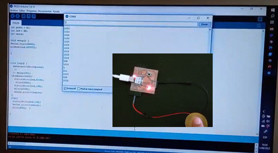
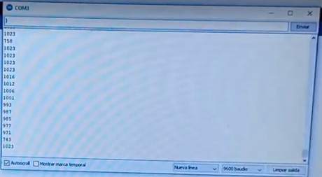
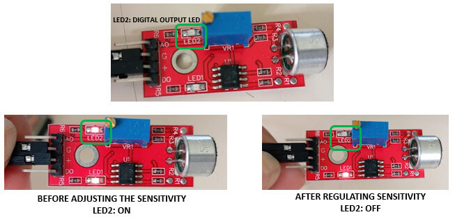
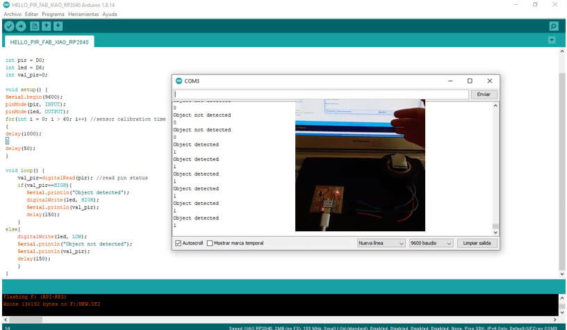
 In this image you can see the "object detected" / "object not detected" message using the arduino serial monitor.
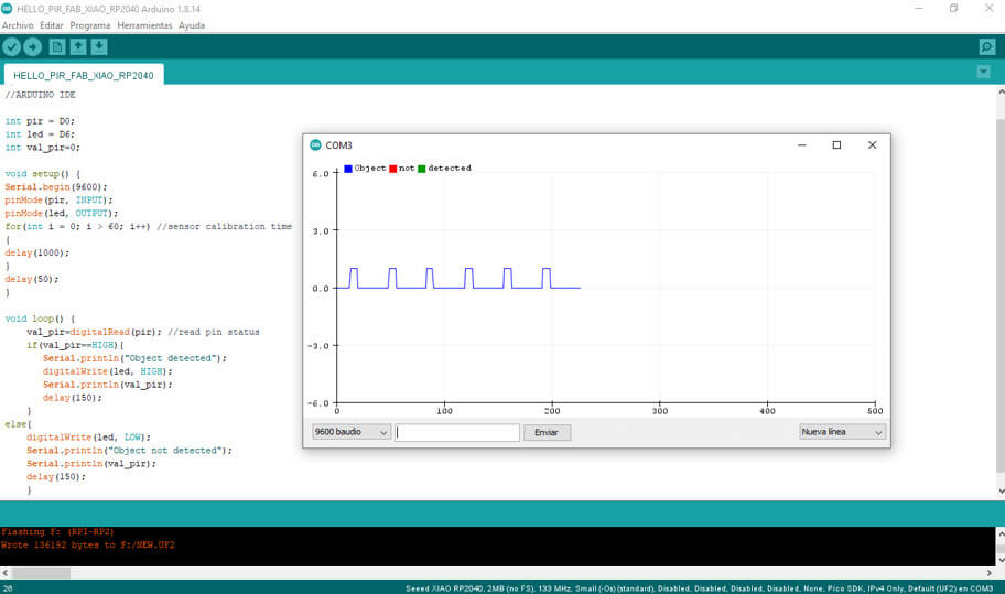
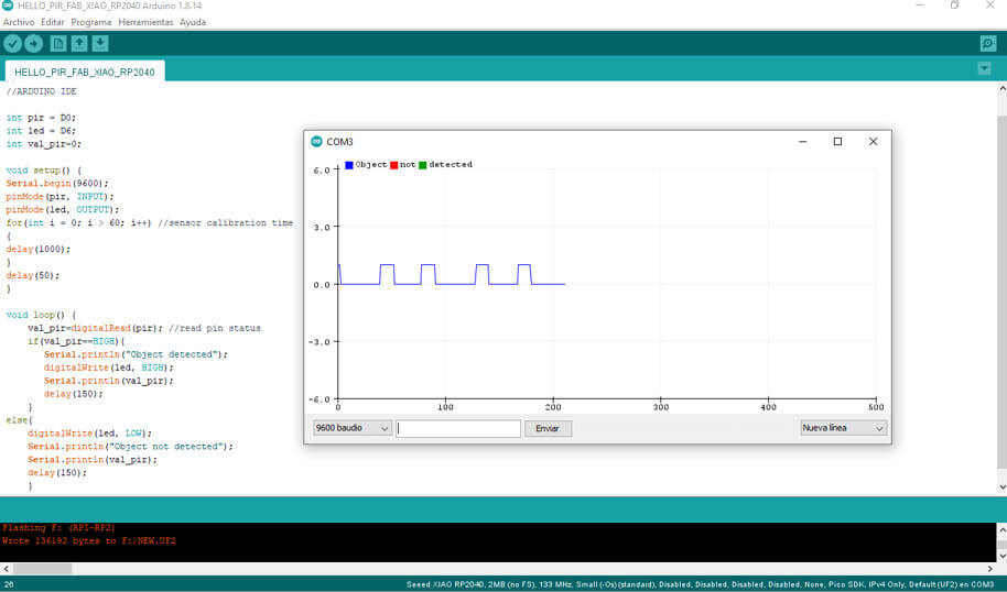
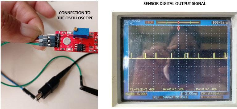
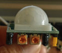
 In this image you can see the behavior of the sensor's output signal every time the object is detected, for this I use the "serial plotter" option of arduino. Observe how the width of the square wave varies, when changing with the potentiometer, the duration of the pulse.