In this section we list the activities to be solved in the following table:
| Checklist | Estatus |
|---|---|
| Linked to the group assignment page |
Finished |
| Documented your project and what you have learned from implementing networking and/or communication protocols. | Finished |
| Explained the programming process(es) you used. | Finished |
| Outlined problems and how you fixed them. | Finished |
| Included design files (or linked to where they are located if you are using a board you have designed and fabricated earlier) and original code. | Finished |
| Included a ‘hero shot’ of your network and/or communications setup | Finished |
- Send a message between two projects
- Document your work to the group work page and reflect on your individual page what you learned
I will also do this assignment individually.
Serial communication in Arduino is a form of communication between devices in which data is sent and received one bit at a time over a communication channel. Serial communication between two devices only uses 3 lines which are: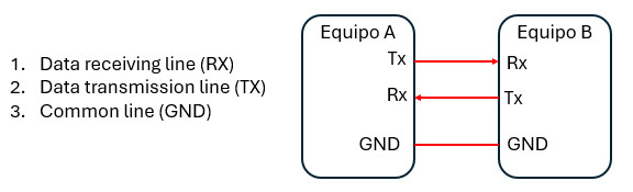 For this assignment I will use:
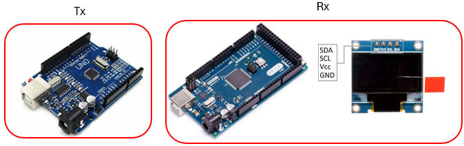
The GND, RX and TX of the Arduino can be easily identified on the board. Here I indicate how many serial ports and pins the Arduino UNO and Arduino MEGA 2560 have.
Arduino UNO: Pins 0 (RX) and 1 (TX);
Arduino Mega: Features four serial ports.
The Arduino UNO will be the transmitter and the Arduino Mega 2560 will be the receiver. The OLED screen will be connected to the Arduino Mega.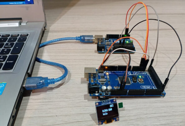
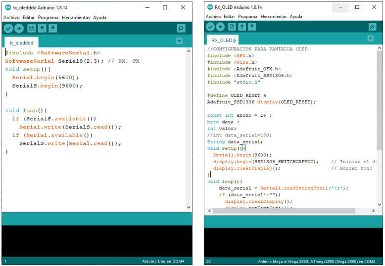
According to some tutorials, in order to achieve communication between the two boards (Arduino UNO and Arduino Mega) it is necessary to create a serial port through software. The SoftwareSerial library allows serial communication on other digital pins of an Arduino board, using software to replicate the functionality (hence the name "SoftwareSerial"). It is possible to have multiple software serial ports with speeds up to 115200 bps. A parameter enables inverted signaling for which devices require that protocol. This library is included in the transmitter program. I will maintain the communication speed at 9600 bps.
#include <SoftwareSerial.h>
SoftwareSerial SerialS(2,3); // RX, TX
void setup(){
Serial.begin(9600);
SerialS.begin(9600);}
void loop(){
if (SerialS.available())
Serial.write(SerialS.read());
if (Serial.available())
SerialS.write(Serial.read());}
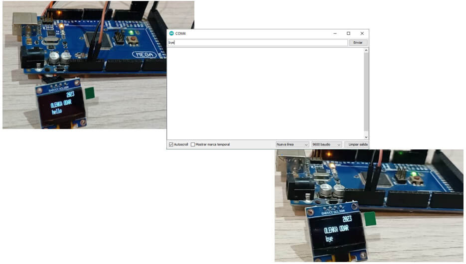
The receiver will display the message sent through the OLED screen (I based my program on the embedded programming assignment example). This OLED screen works via I2C communication. Each message will remain visible until a new message is sent. Here serial1 of the Arduino Mega is used, so pins 18 and 19 are used for connection.
#include <SPI.h>
#include <Wire.h>
#include <Adafruit_GFX.h>
#include <Adafruit_SSD1306.h>
#include "stdio.h"
#define OLED_RESET 4
Adafruit_SSD1306 display(OLED_RESET);
const int ancho = 16 ;
byte data ;
int valor;
String data_serial;
void setup(){
Serial1.begin(9600);
display.begin(SSD1306_SWITCHCAPVCC);
display.clearDisplay(); }
void loop(){
data_serial = Serial1.readStringUntil('\r');
if (data_serial!=""){
display.clearDisplay();
display.setTextSize(1);
display.setTextColor(WHITE);
display.setCursor(30,11);
display.println("OLENKA ODAR ");
display.setCursor(85,0);
display.println("2023");
display.setTextSize(1);
display.setCursor(31,21);
display.println(data_serial);
display.display(); } }
Generally on the Arduino UNO the pins assigned for Tx and Rx are respectively 1 and 0, but using the SoftwareSerial library it is possible to create additional software serial ports; This is very useful if we want to communicate two serial enabled devices or to communicate with a single device leaving the main serial port open for debugging purposes.
- Design, build, and connect wired or wireless node(s) with network or bus addresses
 For this part I will need:
What I will do in this exercise is test the serial port of my FAB XIAO RP2040 receiving a data sent from the Arduino UNO.
The Arduino UNO board will be my transmitter and the FAB XIAO RP2040 will be my receiver.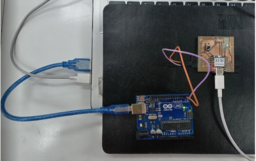
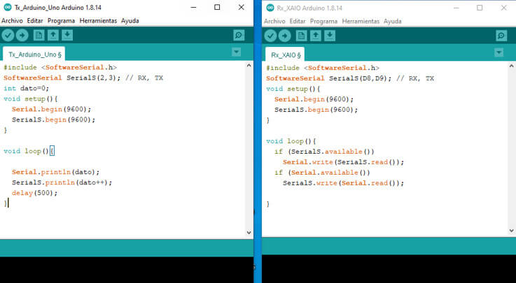
In this program I use the "SoftwareSerial" library to create a virtual port and be able to assign pins 2 and 3 as Rx and Tx. This program will send a value through the serial port that will increase, this value must be read through the serial port of the FAB XIAO RP2040.
In both programs we will work with a speed of 9600bps.
//code made by Olenka Odar
//Fab Academy 2023
//ARDUINO UNO - Tx
#include <Softfware.Serial.h>
SoftwareSerial SerialS(2,3); // RX, TX
int dato=0;
void setup(){
Serial.begin(9600);
SerialS.begin(9600);}
void loop(){
Serial.println(dato);
SerialS.println(dato++);
delay(500);}
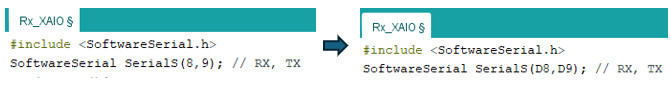
In this program I use the "SoftwareSerial" library to create a virtual port and be able to assign pins D8 and D9 as Rx and Tx. With this program you can see the data sent by the Arduino UNO through the serial monitor associated with the serial port used by the FAB XIAO.
//code made by Olenka Odar
//Fab Academy 2023
//FAB XIAO RP2040 - Rx
#include <Softfware.Serial.h>
SoftwareSerial SerialS(D8,D9); // RX, TX
void setup(){
Serial.begin(9600);
SerialS.begin(9600);}
void loop(){
if (SerialS.available())
Serial.write(SerialS.read());
if (Serial.available())
SerialS.write(Serial.read());}
The data is received correctly, the serial port of the FAB XIAO RP2040 works without problems.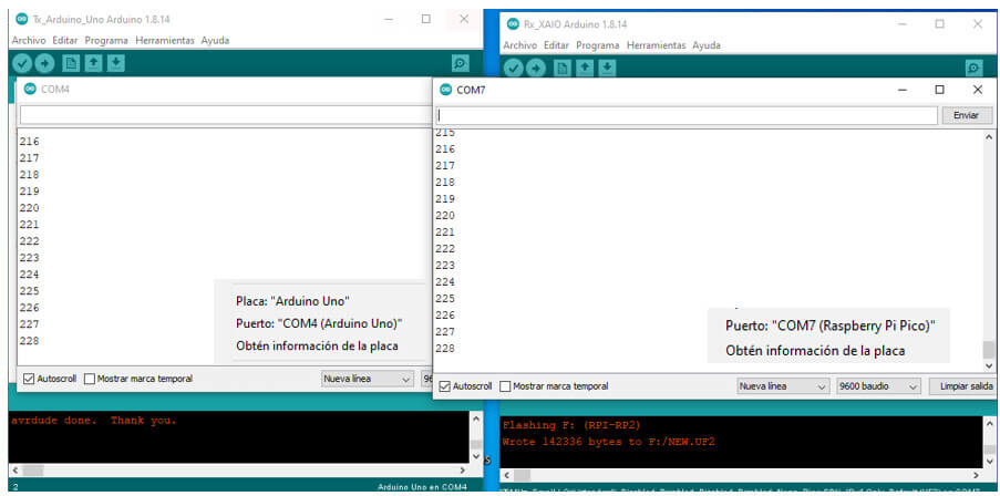
In this exercise I will try to communicate through the Serial Bus two nodes (Arduino UNO and Arduino MEGA boards that will be connected to a motor each) with a bridge (FAB XIAO RP2040 that will activate the LED included on the board). To make this example I take as a basis what was done by Adrian Torres.
The Arduino UNO and Arduino Mega boards will be nodes 1 and node 2 respectively, the XIAO RP2040 board will be the bridge.

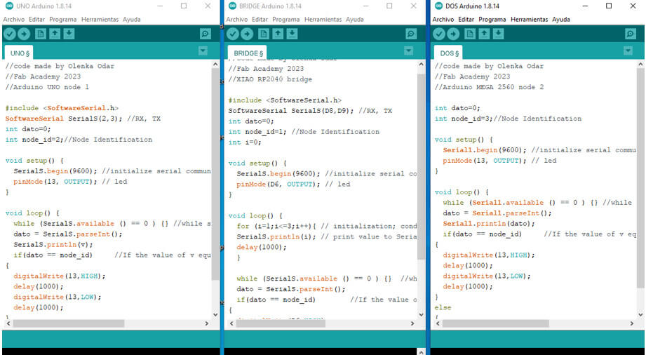
In this program I use the "SoftwareSerial" library to create a virtual port and be able to assign pins D8 and D9 as Rx and Tx as was done in the previous examples. To identify the node on the bus I use "int node_id= 1". This program performs an increment from 1 to 3 and if the data is equal to the node identifier, it executes what is in the void loop. I assign pin D6 (which is connected to an LED) as the output pin. In all programs I will work with a speed of 9600bps.
//code made by Olenka Odar
//Fab Academy 2023
//FAB XIAO RP2040 bridge
#include <SoftwareSerial.h>
SoftwareSerial SerialS(D8,D9); //RX, TX
int dato=0;
int node_id=1; //Node Identification
int i=0;
void setup() {
SerialS.begin(9600); //initialize serial communications
pinMode(D6, OUTPUT); // led
}
void loop() {
for (i=1;i<=3;i++){
SerialS.println(i); // print value to Serial
delay(1000); }
while (SerialS.available () == 0 ) {} //while serial is 0
dato = SerialS.parseInt();
if(dato == node_id) //If the value of dato equals the identification of the node
{ digitalWrite(D6,HIGH);
delay(1000);
digitalWrite(D6,LOW);
delay(1000);}
else
{
digitalWrite(D6,LOW); }}
In this program I use the "SoftwareSerial" library to create a virtual port and be able to assign pins 2 and 3 as Rx and Tx as was done in the previous examples. To identify the node on the bus I use "int node_id= 2" if the data is equal to the node identifier, it executes what is in the void loop. I assign pin 13 as the output pin.
//code made by Olenka Odar
//Fab Academy 2023
//Arduino UNO node 1
#include <SoftwareSerial.h>
SoftwareSerial SerialS(2,3); //RX, TX
int dato=0;
int node_id=2;
void setup() {
SerialS.begin(9600);
pinMode(13, OUTPUT); }
void loop() {
while (SerialS.available () == 0 ) {}
dato = SerialS.parseInt();
SerialS.println(dato);
if(dato == node_id)
{ digitalWrite(13,HIGH);
delay(1000);
digitalWrite(13,LOW);
delay(1000);}
else
{
digitalWrite(13,LOW); }}
In this program I do not use the "SoftwareSerial" library, since this card has 4 serial ports available. I will just use "Serial 1.begin" and pins 19 and 18 are assigned as Rx and Tx. To identify the node on the bus I use "node_id=3" and if the data is equal to the node identifier, execute what is in the void loop. I assign pin 13 as the output pin.
//code made by Olenka Odar
//Fab Academy 2023
//Arduino MEGA 2560 node 2
int dato=0;
int node_id=3;
void setup() {
Serial1.begin(9600);
pinMode(13, OUTPUT);
}
void loop() {
while (Serial1.available () == 0 ) {}
dato = Serial1.parseInt();
Serial1.println(dato);
if(dato == node_id)
{ digitalWrite(13,HIGH);
delay(1000);
digitalWrite(13,LOW);
delay(1000);}
else
{
digitalWrite(13,LOW); }}
created with
HTML Creator .