In this section we list the activities to be solved in the following table:
| Checklist | Estatus |
|---|---|
| Linked to the group assignment page | Finished |
| Documented how you made (mill, stuff, solder) the board | Finished |
| Documented that your board is functional | Finished |
| Explained any problems and how you fixed them | Finished |
| Included a "hero shot"of your board | Finished |
The machine is MONOFAB SRM-20 is like a small milling machine, the SRM-20 offers a compact size and powerful functionality at an affordable price. Producing realistic parts and prototypes is made simple and convenient with a device that fits in any office, classroom, or home. For users looking for advanced milling skills without the need to be an expert, the SRM-20 is the most precise and easiest to operate milling machine in its class.
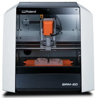 A wide range of materials, including wax, chemical wood, foam, acrylic, polyacetal, acrylonitrile butadiene styrene (ABS), and printed circuit boards, can be precision milled using the SRM-20 small milling machine, allowing you to create realistic 3D prototypes that are identical to the production parts.
The SRM-20 has a fully enclosed cabinet that reduces dust and noise and includes a side window for easy viewing of progress. It also includes a safety interlock switch that automatically puts the machine into pause mode when the cover is open, allowing milling to restart when you close the cover and select “continue” (“continue”). Multi-axis milling is as easy as X, Y and Z.
Specifications
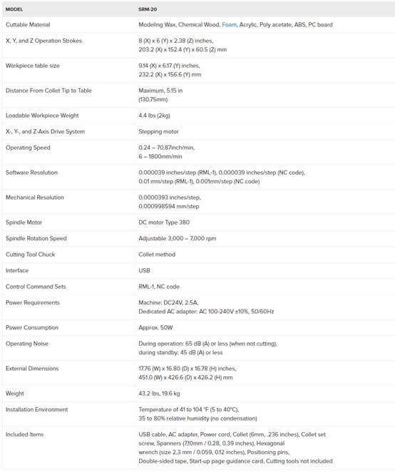
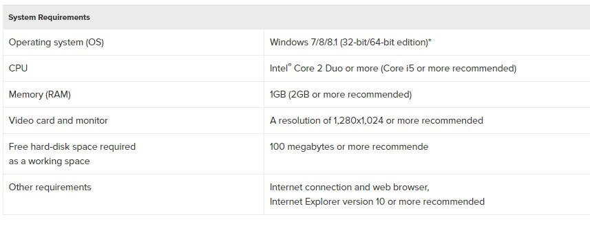
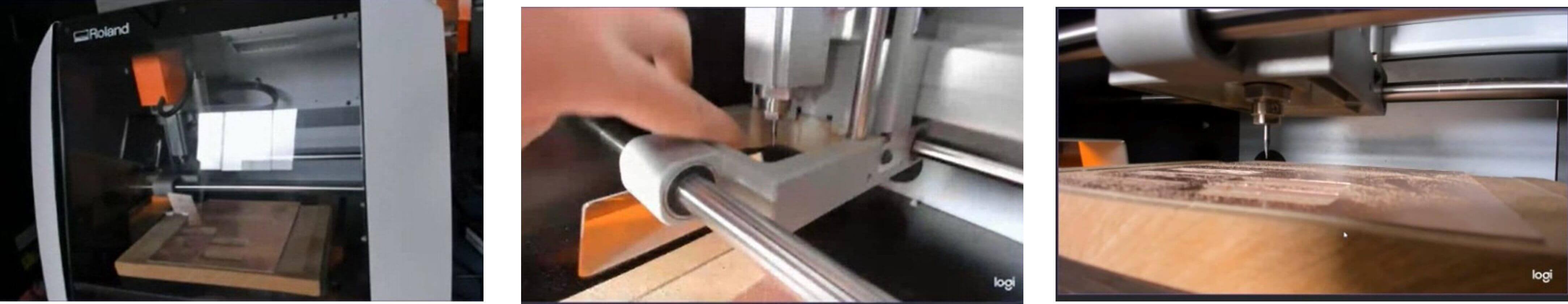
You can see images of the milling machine
Remember
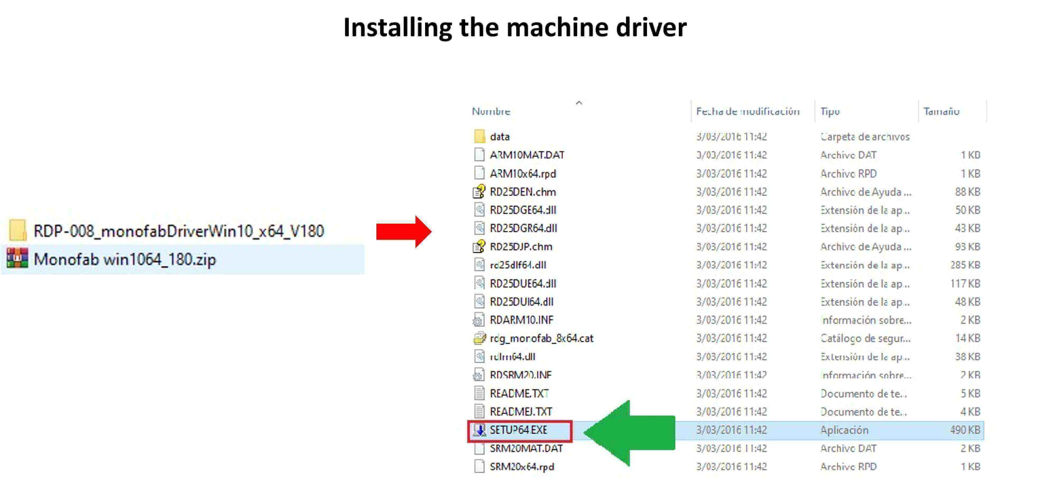
The two important components that will allow us to work with the machine are: the machine driver and the software that controls the machine.
Run the SETUP64 file
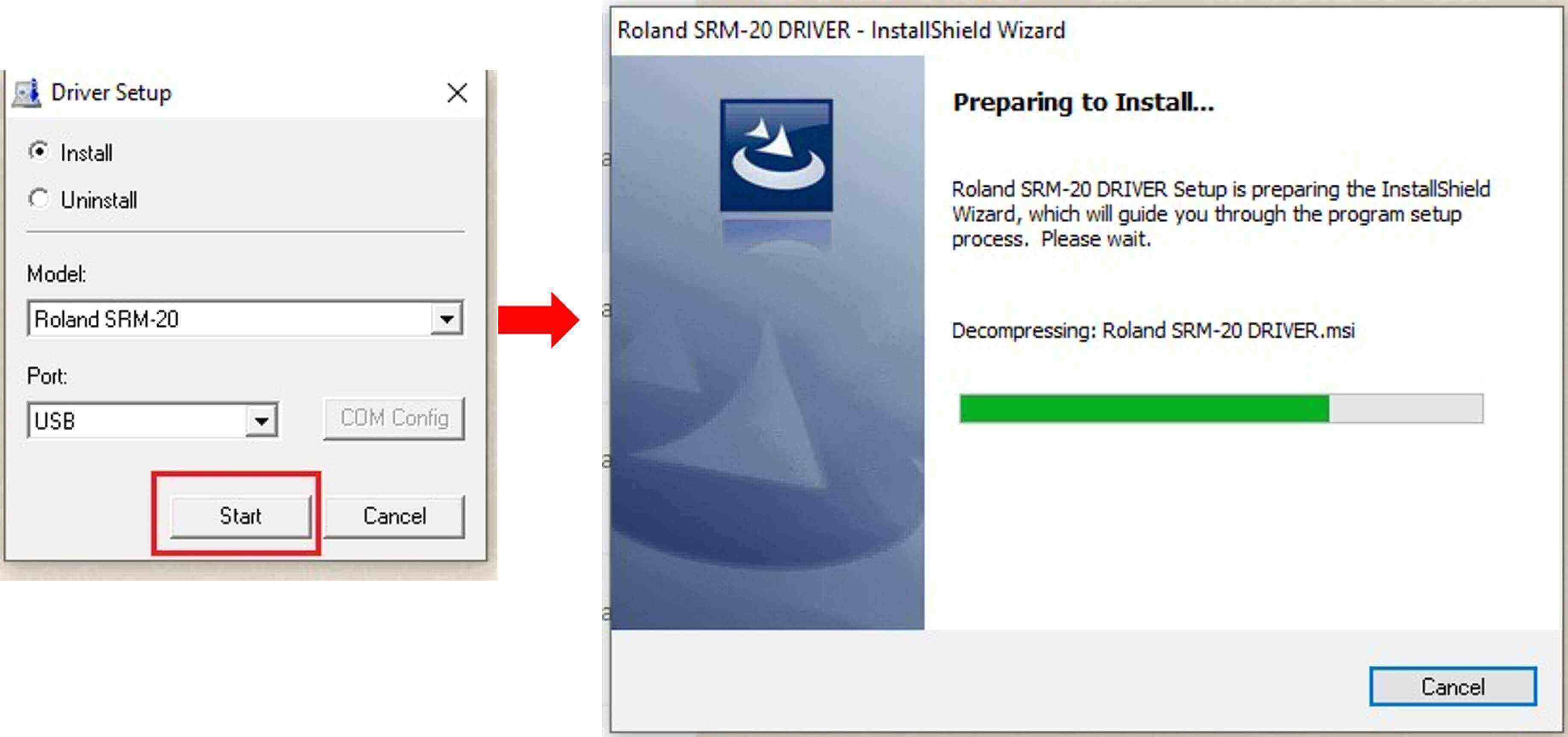
Mark the INSTALL option and then press START for the installation to start.
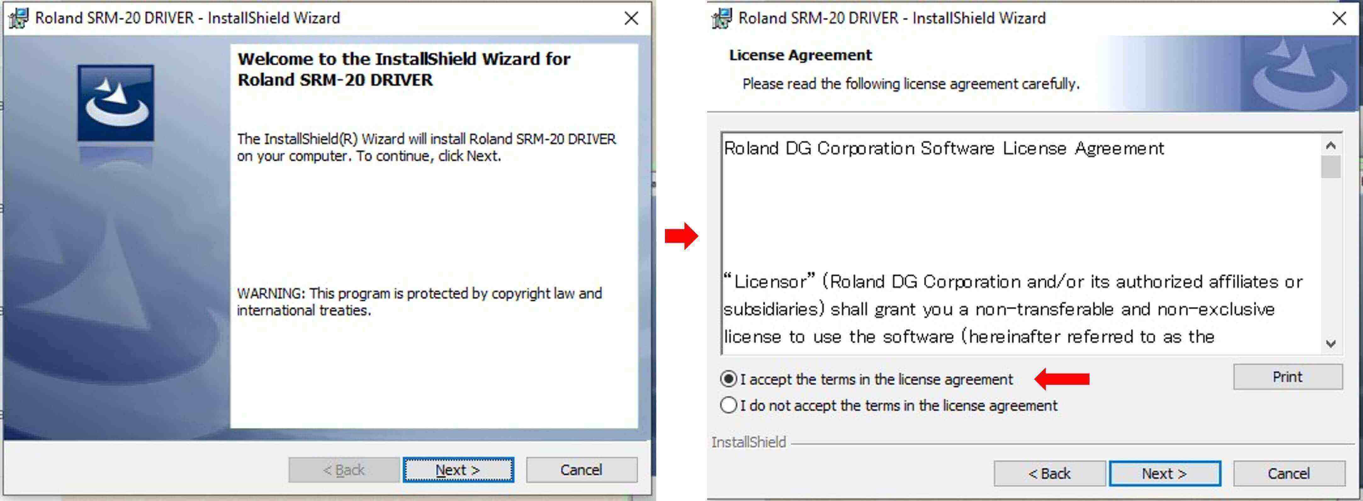
We must press the NEXT button. We must accept the terms of the license and then click on NEXT.
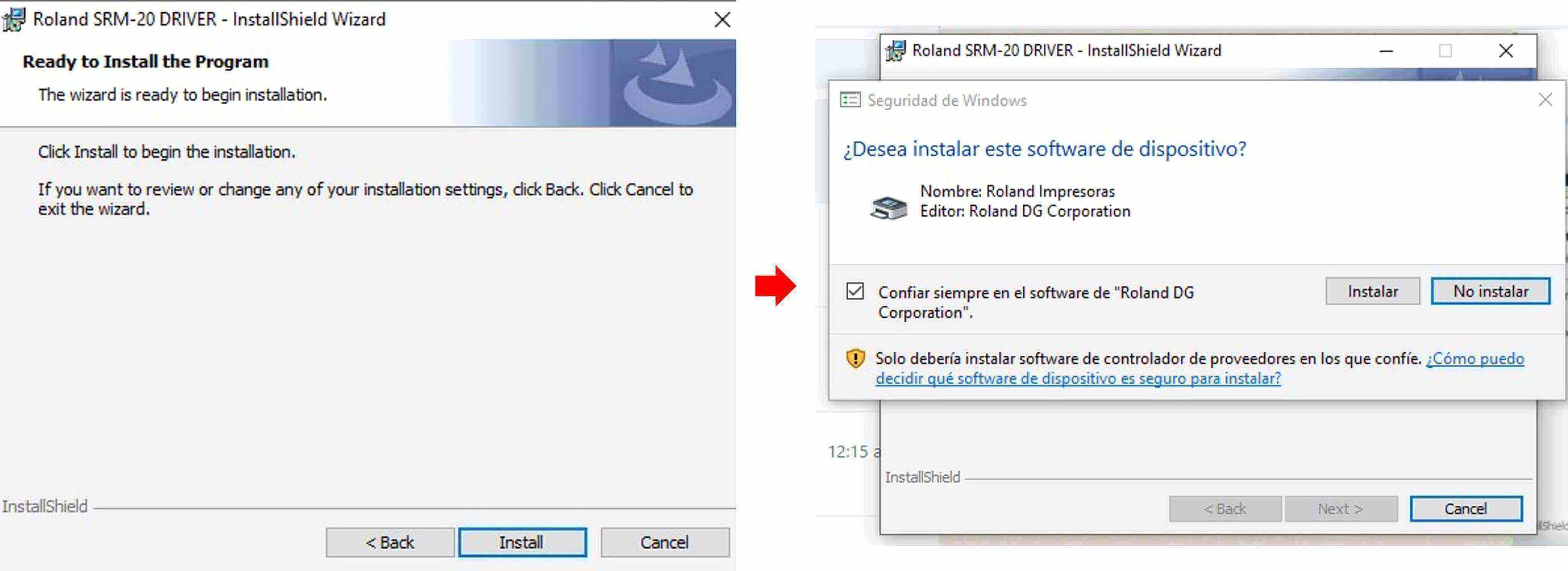
We press INSTALL to start the installation and then we confirm that we are going to install the device by clicking on INSTALL.
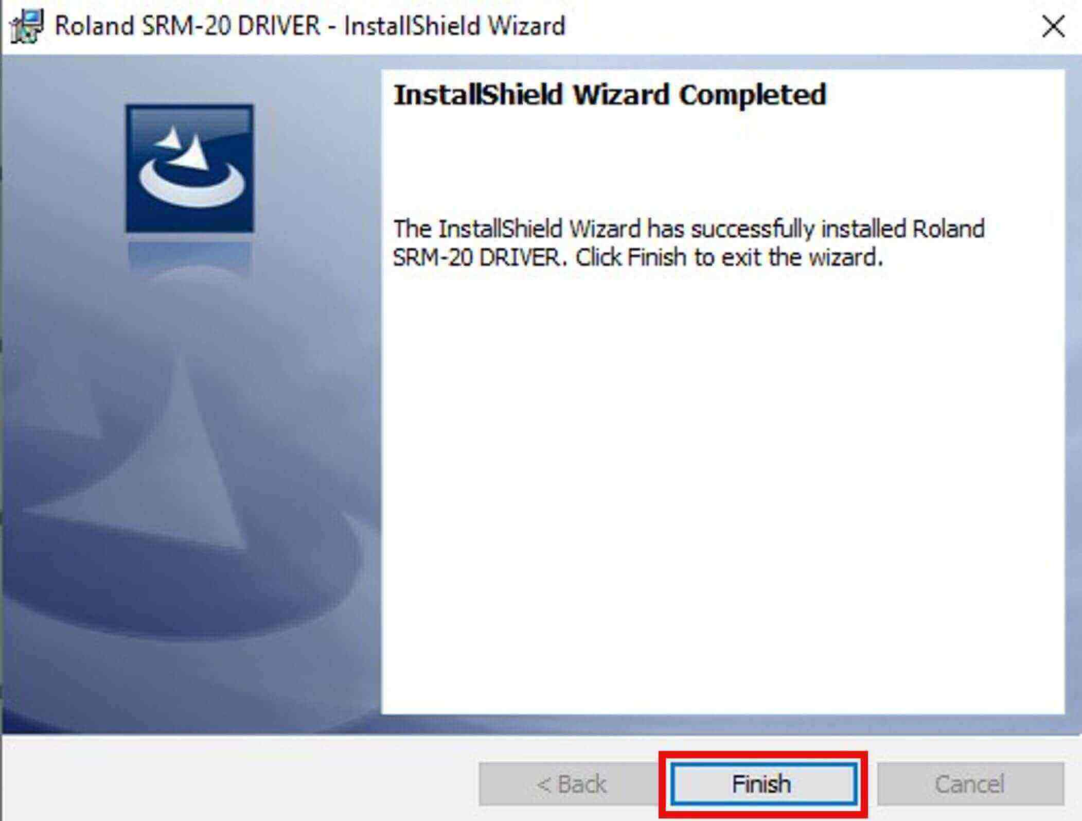
After the installation, press the FINISH button.
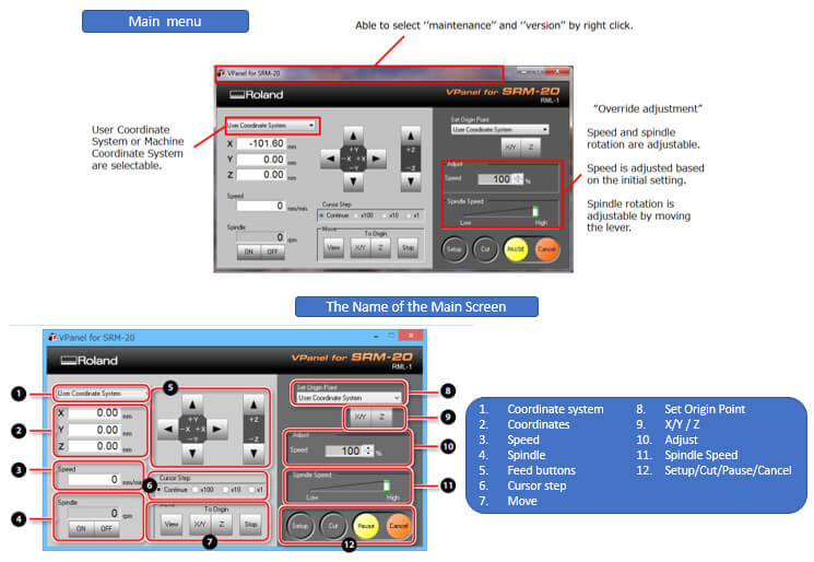
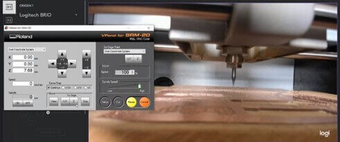
The SRM-20 was designed with a number of technological advances, including a VPanel controller that allows regulation of feed rate, spindle speed, and milling in all three X, Y, and Z axes, and a new independent drive system. Drill chuck that allows faster Z-axis base point setup and quick tool changes.
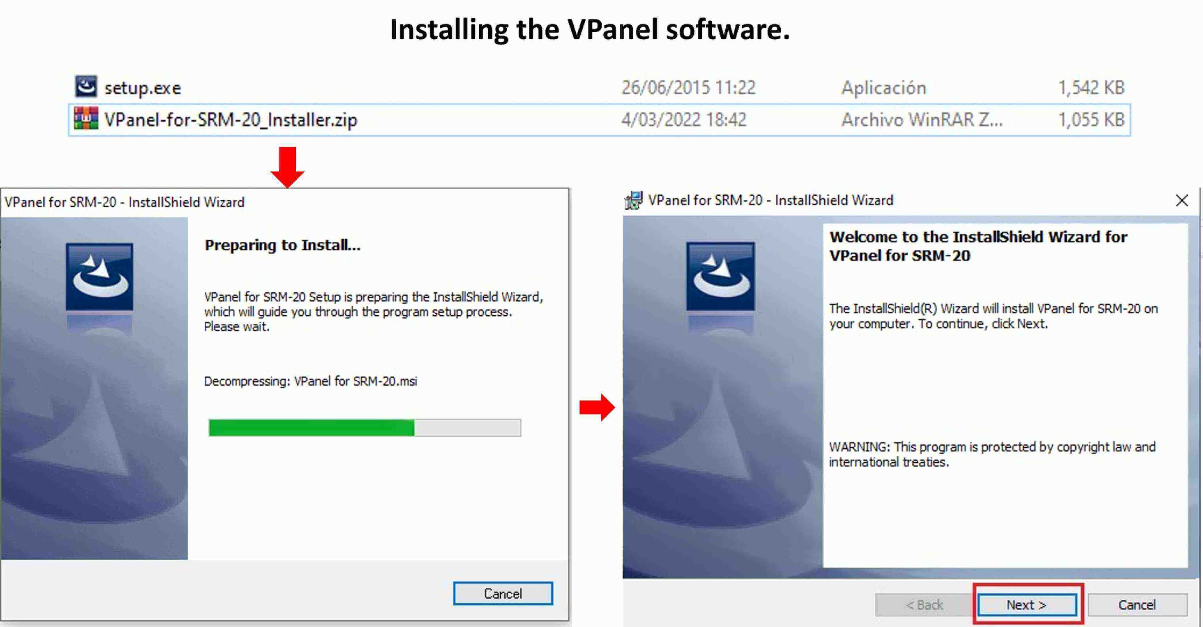
It is the dedicated software for controlling this machine. Operation of this machine and various setup are performed using this software.
We execute the SETUP file and the installation is prepared in the following window, we press NEXT to start the installation wizard.
We accept the terms of the software license and press the NEXT button and then we can indicate the destination of the installation files by pressing the NEXT button. 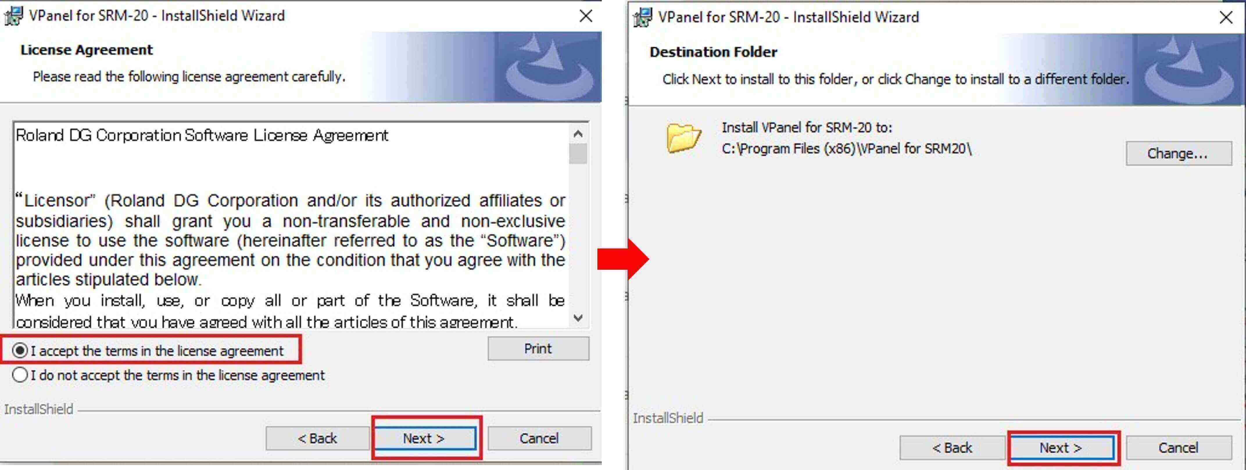
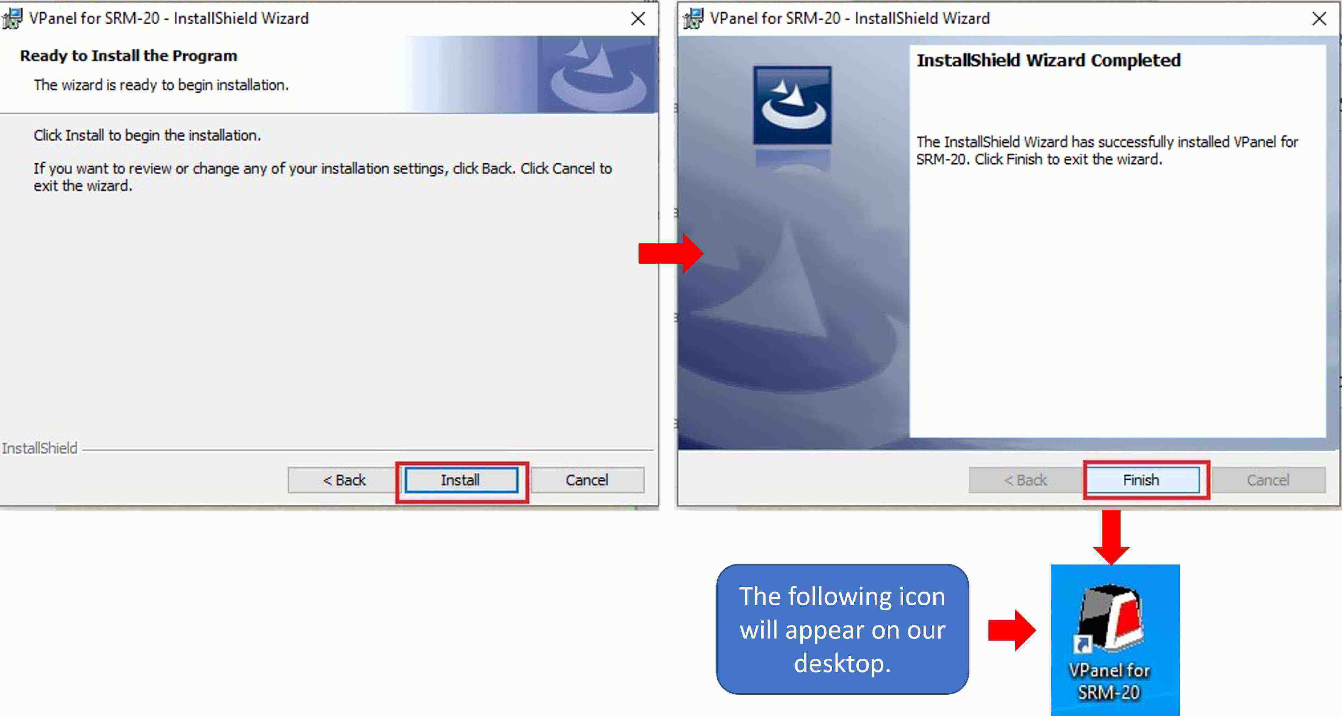
We start the installation by pressing the INSTALL button and at the end we press FINISH. We will see that on the desktop.
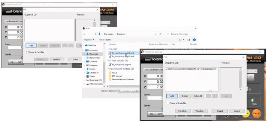
We must test the operation of the MONOFAB SRM-20 machine before making our PCBs. To do this we must carry out two processes: the trace of the tracks and the cutting of the contour of the plate. We will use the online test that Neil taught us, which are in “png” format.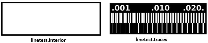 Now it is necessary to obtain a file that accepts the MONOFAB SRM-20, for this we will process the test images in MODSPROJECT to obtain files with the "rml" extension. In a new browser tab we enter the following link https://modsproject.org.
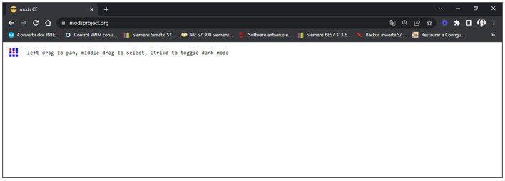 When entering the following window appears, we right click on the work area; follow the steps shown below.
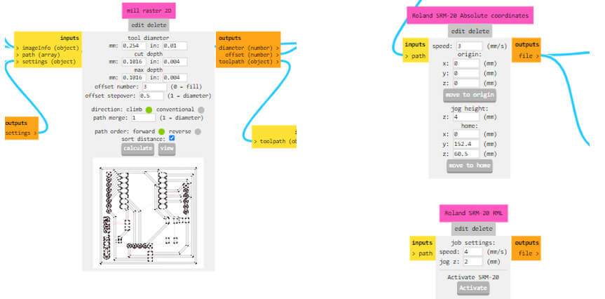
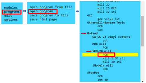 After choosing Roland SRM-20 mill PCB, a new window appears with several boxes, but don't worry, not all of them will be used, if the file format is .png the following will be used:
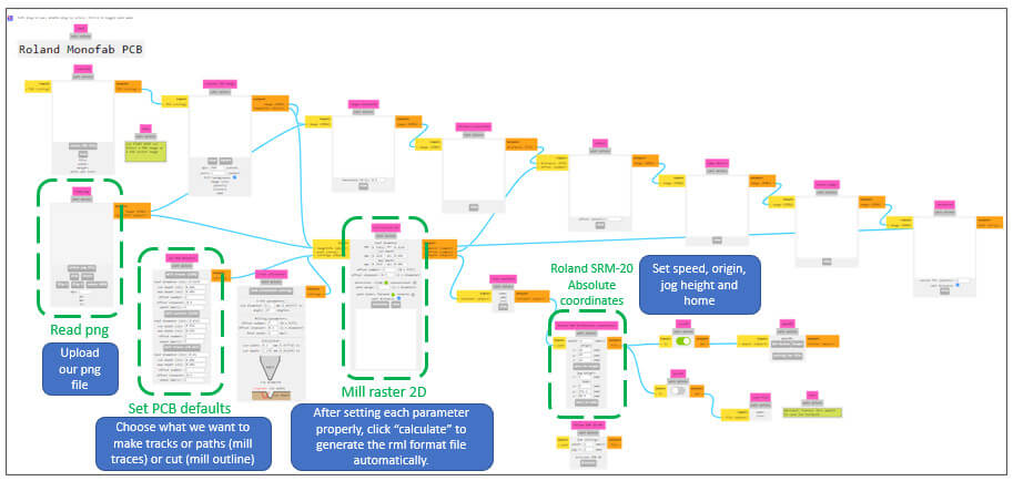
In “read png” we select the png file to trace the lines, then in “set PCB defaults” click on “mill traces (1/64)”.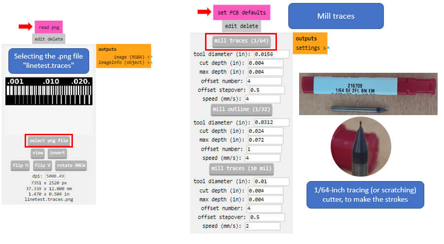 By clicking on “mill traces (1/64)” the value of the cutting depth is calculated in “mill raster 2D”, which by default is 0.1016 mm and the number of passes is 4.
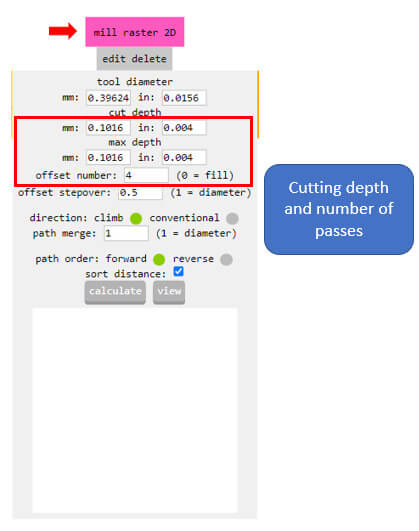 We set the (x, y, z) coordinates to (0, 0, 0) and keep the scroll speed at 4mm/s, the scroll height at 2mm.
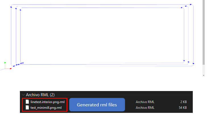
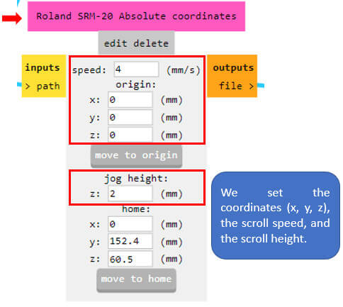 Once we have all the configurations ready, click on "calculate" to generate the ".rml" file that will be downloaded to our computer. You can see how the route of the milling machine will be.
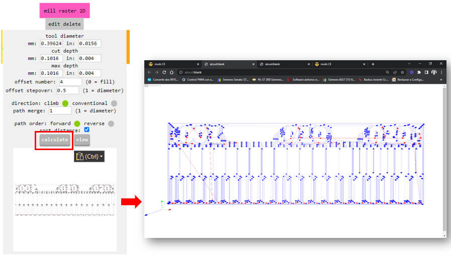
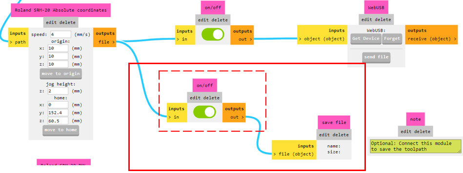
Important: Do not forget to enable the option that allows to automatically download the rml file to the computer. If this step is not carried out, it will not download and they will lose time due to that error (what happened to me).
The steps are similar: we load the file “linetest.interior.png”, we select mill outline (1/32).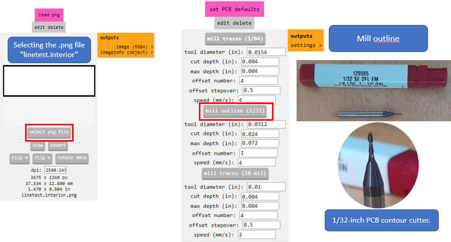
The depth remains at 0.6096 mm and the number of passes at 1. Travel speed at 2 mm/s and the jog height at 4 mm.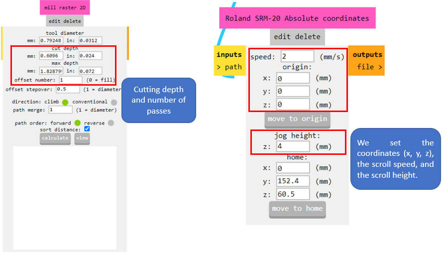
Click on calculate to generate the file in “.rml” format that will also be downloaded to the computer.
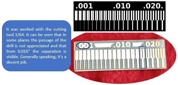
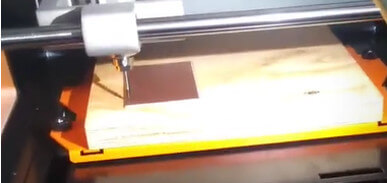
We set up the Roland SRM-20 with the necessary cutting tool (the 1/64-inch bit to do the scribing, then switched to the 1/32-inch bit to do the cutting); to change the strawberries we will use the hexagonal key. Do not forget to secure the bakelite well to the wooden base.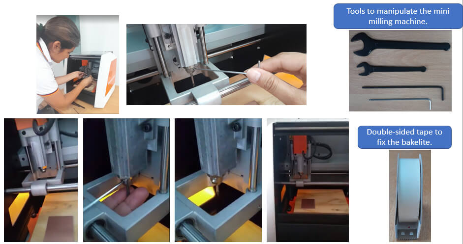
This is the end result, it looks pretty good.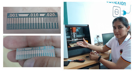
Remember: After setting the origin to start a new milling job, the machine defaults to starting from the bottom left corner up.
- Make an in-circuit programmer that includes a microcontroller by milling and stuffing the PCB, test it to verify that it works.
Below are the steps for the manufacture of a programming card.
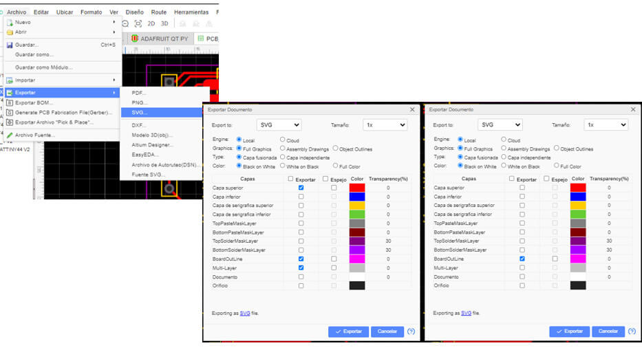
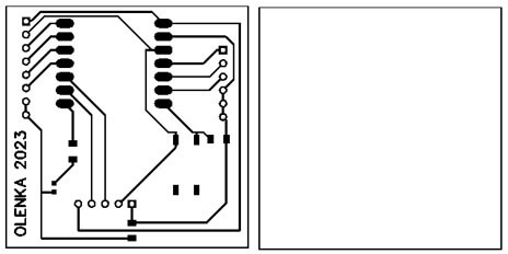
Now I need to implement the card that I designed in the previous assignment. The first thing I have to do is download in .png (pixels) or .svg (vectors) format the upper layer of the PCB that contains the traces and the outline for the cut. This time I will download both files in .svg format.
We use MODSPROJECT as software to parameterize the PCB svg files, and to be able to assemble them from the milling machine. The steps are very similar to those made in the design rules, only this time we will work in "read SVG".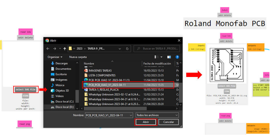
After loading the file in .SVG format, clicking on "mill traces (1/64)" calculates the value of the cutting depth in "mill raster 2D", which by default is 0.1016 mm and the number of passes is 3. Set the (x, y, z ) coordinates to (0, 0, 0) and keep the scroll speed at 3 mm/s, the scroll height at 4 mm.
Once we have all the configurations ready, click on "calculate" to generate the ".rml" file that will be downloaded to our computer.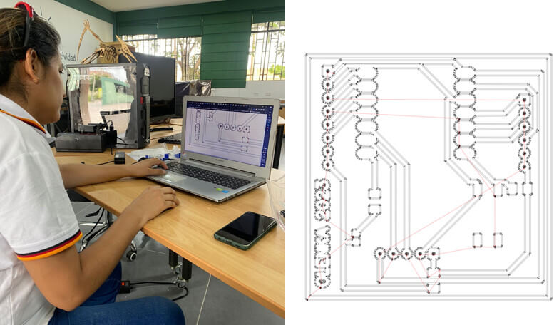
Now we load the cut file, click on mill traces (1/32) and configure as shown in the image.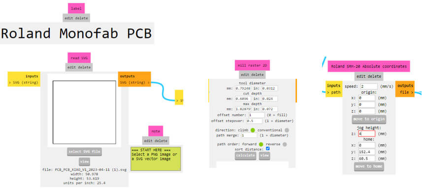
Now I can start the process of milling the plate, I secure the bakelite with double-sided tape to the base, then I put the 1/64 cutting tool first and send the file containing the traces. Finally, I change the cutting tool to 1/32 to make the outline of the plate.
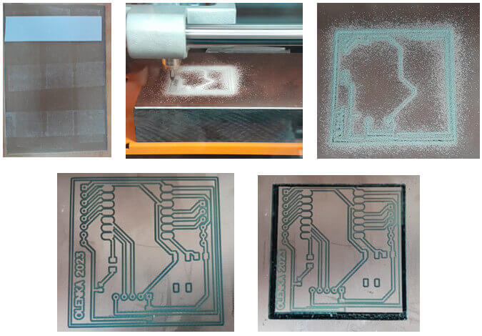
Peel the PCB off the work plate, making sure not to scratch the milled surface. I use the vacuum cleaner to clean all the chips and carefully clean all the edges.
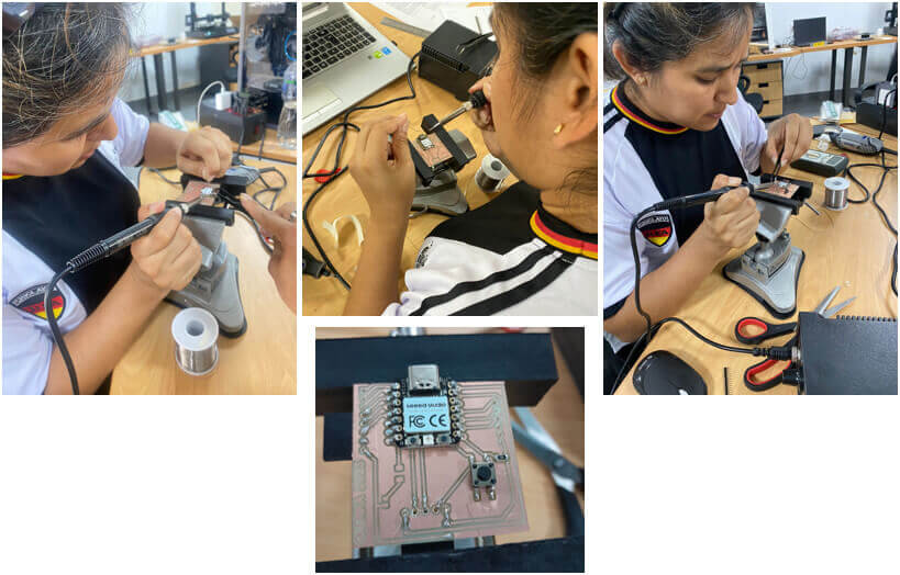
I prepare everything necessary to start welding: welding equipment and electronic components. Let's start!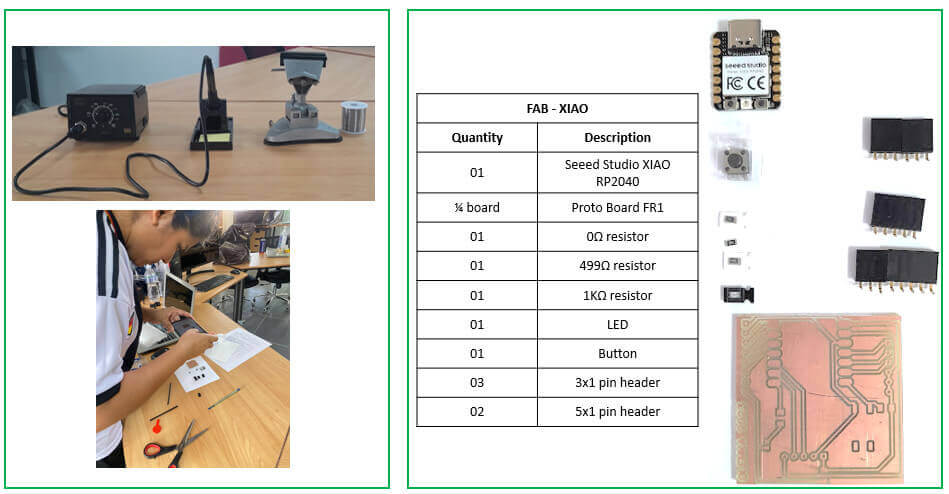
Now I have my own Fab-Xiao, let's program!
Open the Arduino IDE program and add the board: go to File – Preferences – and add the URL of the additional board that you can find in the following link.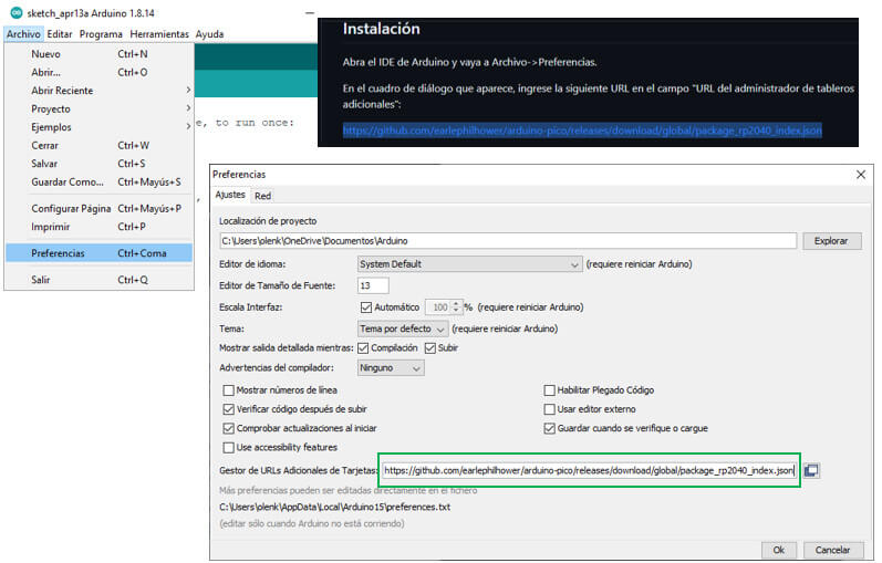
Go to card manager and download Earlephilhower's Raspberry Pi Pico/RP2040.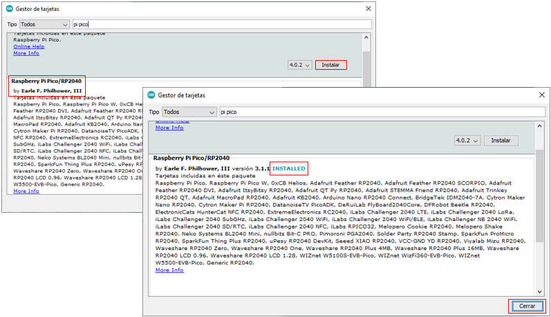
Before programming, in tools we configure the card to be used and we verify in which COM port it appears connected, in my case in COM 3.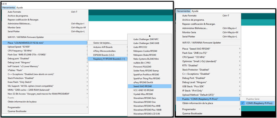
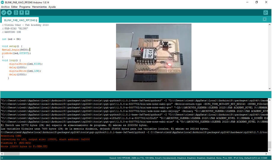
For my first test I load the "blink" program, while sending the program in the message section all that information appears. The program handles the same structure and the same instructions, we just have to be careful in pin assignment; in this case my LED is connected on pin D6.
//Olenka Odar - Fab Academy 2023, FAB-XIAO "BLINK" , ARDUINO IDE
int led = D6;
void setup() {
Serial.begin(9600);
pinMode(led,OUTPUT);}
void loop() { digitalWrite(led,HIGH);
delay(1000);
digitalWrite(led,LOW);
delay(1000); }
For my second program I use the led and push button that are on the board, this time the pins I used are D7 for the push button and D6 for the LED.
//Olenka Odar - Fab Academy 2023 - FAB-XIAO "BUTTON_LED" - ARDUINO IDE
int pulsador = D7;
int led = D6;
int estadopin=0;
void setup() {Serial.begin(9600);
pinMode(led,OUTPUT);
pinMode(pulsador, INPUT);}
void loop() { estadopin=digitalRead(pulsador); //read pin status
if(estadopin==HIGH){
digitalWrite(led,HIGH);
Serial.println(estadopin); }
else{ digitalWrite(led,LOW);
Serial.println(estadopin);
delay(150); }}

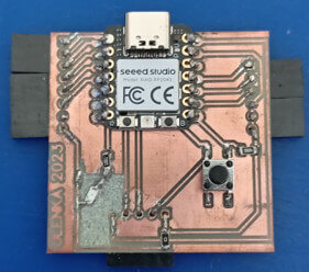
My Fab-XIOA RP2040 card works!
1. According to my design, I needed a 6x1, 5x1 and 8x1 header; There were only 5x1 and 3x1, so I used a total of three 3x1 headers and two 5x1 headers.
2. Before carrying out the milling process for the plate, I tried another design and noticed that the wooden base was very low and the mini router would go up again and not perform the milling and I had to continuously adjust the height of the bit, so I put other wood on top.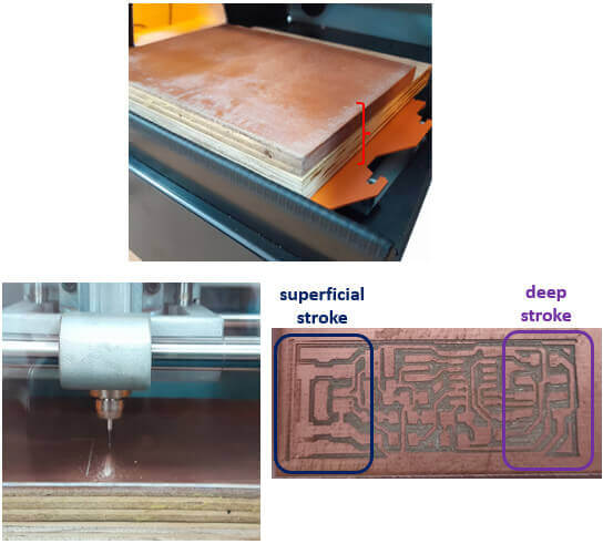
Another problem arose, in some parts of the plate the milling was very superficial, and in others it was very deep. This is because the wood that I placed was not level and also the bakelite was slightly curved. Finally I changed the base again and leveled the plate. It is ready!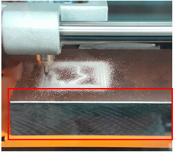
3. The headers were not surface mount so I will drill the holes with a dremel to which I adapted the 1/64 bit.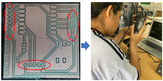
4. As I said in the previous assignment, not all footprints are suitable for a design. I thought all my component traces on the PCB were correct, but when I was going to solder the LED I realized that the trace was smaller and was making contact with other traces, so using the dremel I blasted away the copper around it and it worked. I must take this error into account for a future design.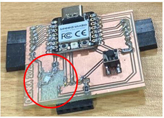
5. According to my design there are connections that pass under the SEEED XIAO RP2040, to avoid short circuits, I took Adrián Torres' advice into account and put double-sided tape behind the SEEED XIAO RP2040 before soldering it.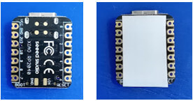
6. The Fab-XIAO RP2040 board is practical and can be programmed with the Arduino IDE, it does not need an additional programmer and that is a great advantage.
created with
Website Builder .