In this section we list the activities to be solved in the following table:
| Checklist | Estatus |
|---|---|
| Linked to the group assignment page and reflected on your individual page what you have learned. | Finished |
| Reviewed the safety data sheets for each of your molding and casting materials, then made and compared test casts with each of them. | Finished |
| Documented how you designed your 3D mold and created your rough and finish toolpaths for machining, including machine settings. | Finished |
| Shown how you made your mold and cast the parts. | Finished |
| Included your design files and ‘hero shot’ of the mold and the final object. | Finished |
- Review the safety data sheets for each of your molding and casting materials
- Make and compare test casts with each of them
I will also do this assignment individually.
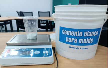
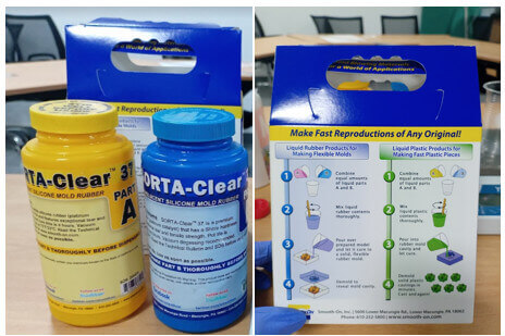
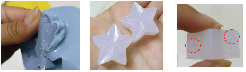
For this assignment I will use three products: resin + hardener, silicone and white cement for molds.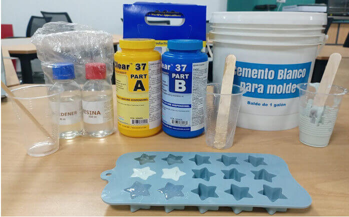
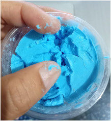
 Mix
Mix
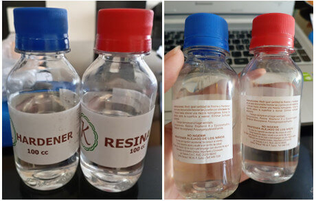
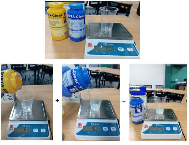
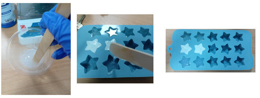
Following the instructions, I mixed both products as shown in the images.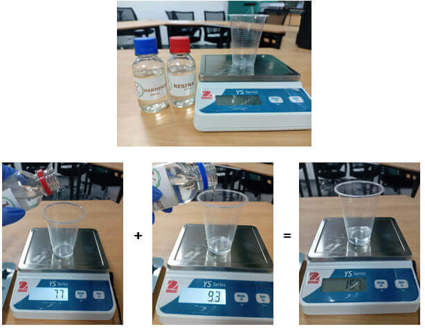
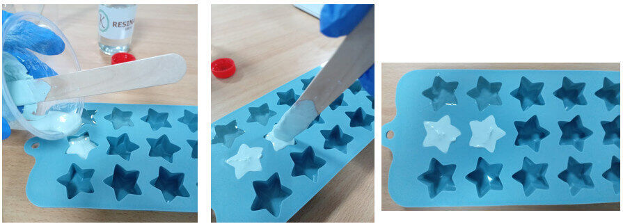
After mixing the two products for a minute, we pour the mixture into the mold. I will use a star-shaped silicone mold for the three different products.

Design a mold around the stock and tooling that you'll be using, mill it (rough cut + (at least) three-axis finish cut), and use it to cast parts.
For this task I will do the design in FreeCAD, but there is a detail for the milling of the machinable wax, I will work with the 1/32 milling tool, so my design cannot be very deep. I will have to make a 3mm deep design.
I choose a simple design, I will make a gear. (You can tell I'm running out of ideas.) I will use FREECAD. Open FREECAD. In the workbench selector, select the "Part Design" option.
Go to "Part Design" and choose "Involute gear". I create a first gear of 26 teeth. Click "Ok".
I repeat the same steps to create another 15 tooth gear in the center. Click "Ok".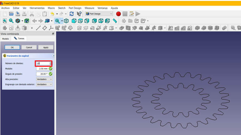
Now in the workbench selector, choose the "Part" option. Select the smallest gear and make an extrude of 5mm.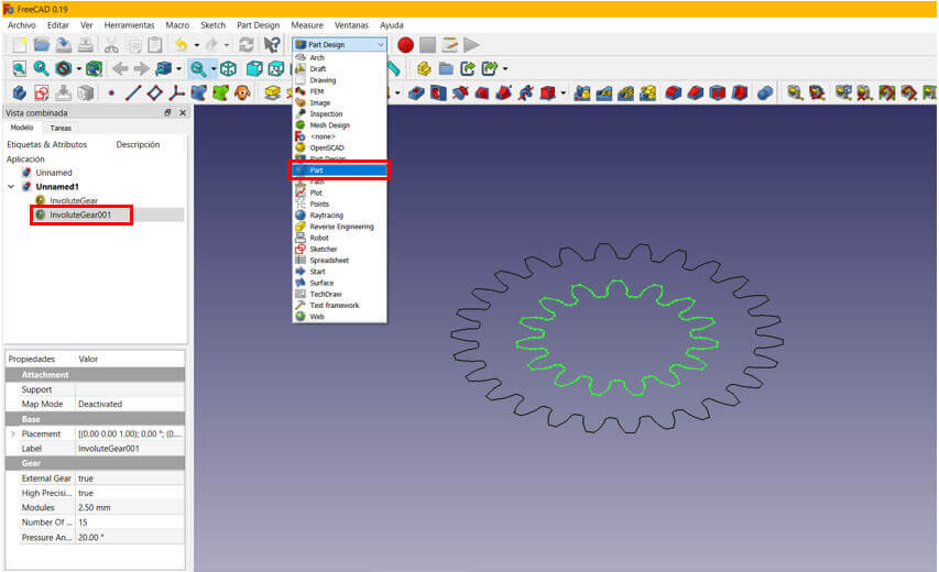


To the 26 tooth gear, make an extrude of 3mm.
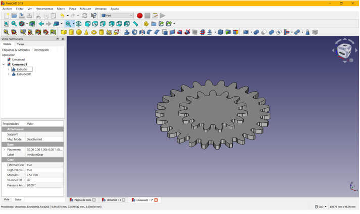
Finally we apply a cut instruction and the gear is ready.
It is important to note the following: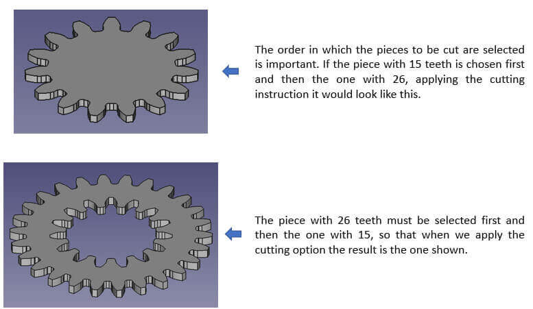
Once the design is done, we must export the file in STL format to be able to process it in Mods CE and thus obtain the "rml" file that will be used in the Roland SRM20 mini-mill.
I will be using the Roland SMR20 mini mill, which I explained in week 09, to do the machinable wax milling. I will also work with Mods CE to obtain the file with the "rml" extension that will be taken to the minimill.

Enter the diameter of the cutter to be used, as I said above, I will use the cutting tool 1/32 or 0.03125 in.
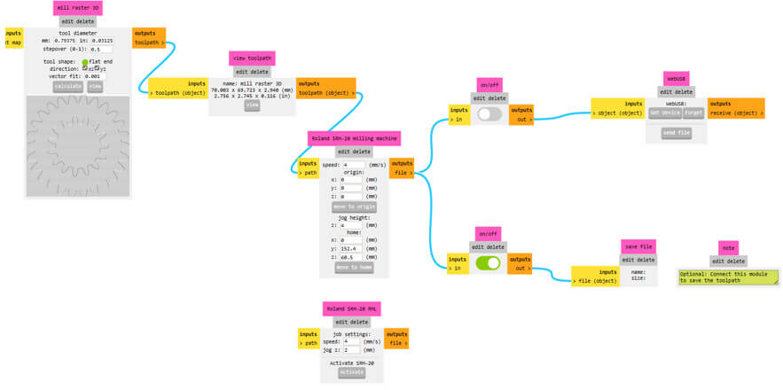

Download the "rml" file and we are ready to start milling in the machinable wax.

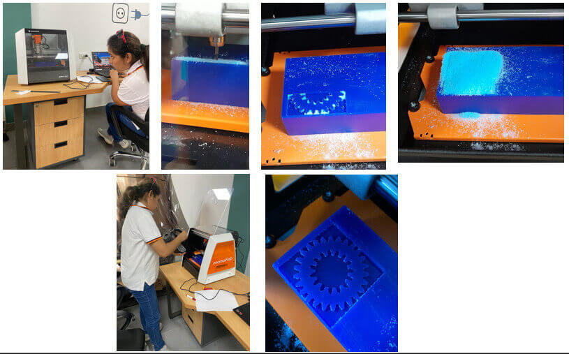
Once we have milled the wax mold, we have to prepare the silicone mold. To obtain the negative of the piece. Let us begin!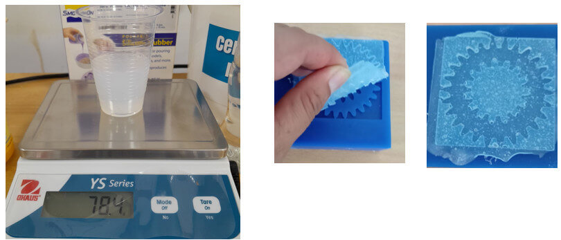
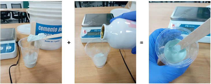
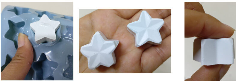
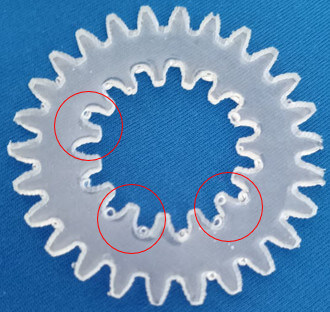
My first choice was to use the white mold cement. We see how it turned out.

 Apparently because the mold was not very deep, when trying to remove the piece it broke into several parts.
For my second test I used resin + hardener, the results were different. It turned out much better!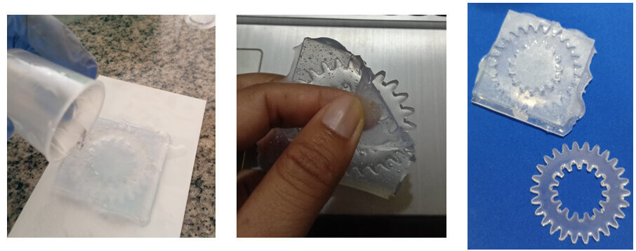
Download the files here.
To meet the specifications of the assignment, three-axis machining, I will make the mold of a roller for a mecanum wheel.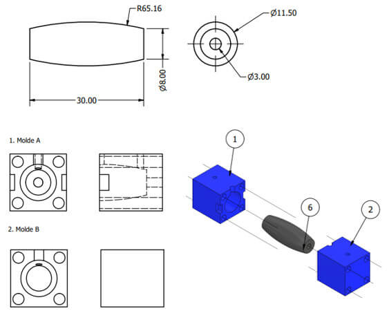 What are Mecanum wheels and what are they used for?

Mecanum wheels allow a vehicle to move in all directions and is oriented at one point, the wheel consists of passive rollers oriented at 45º to the wheel's circumference. These wheels are used in robots that require complete movement in small spaces, where orientation is important.
I need to make the mold for a roller from a Mecanum 609 wheel roller mold, and I will do it using solid subtraction. The roller mold consists of three pieces, so let's start with its design.
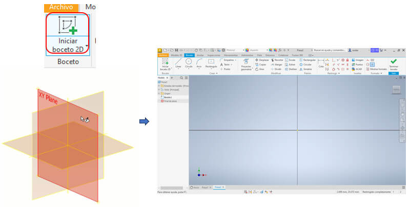
We open Inventor, create a new file and select the "Standard.ipt" option, then we create a new sketch and choose a plane (XY).
With "rectangle" (in the two-point center option) we create a 18x18mm square in it.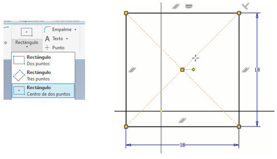 Then we must draw a 3.5mm circle in each corner of the frame (for the mold holding bolts). To do this, we use the "circle" command, we can draw the circle first and then limit it with "Dimension" with this same tool, we place it 2.5mm from the corner as shown in the figure. Then we use a circular pattern, we choose the central axis and indicate that there will be 4 circles and press enter.
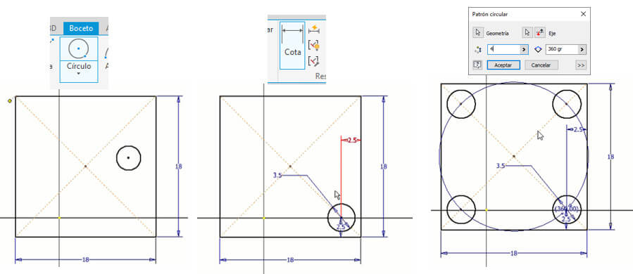 Click on "Finish Sketch", select the figure and extrude it 20mm with "Extrude".
Now we make a plane between two planes to be able to draw the profile of the roller (of which we already have its dimensions) and obtain the mold of the middle of the roller. Go to the "3D Model" tab, click on "Plane", choose "middle plane between two planes" and select the two side faces to create the plane. Then we need to generate a section view. Go to the "View" tab and choose "Half Section View" and select the created middle plane. We create a sketch on that section and there we will draw the profile of the roller. With the "Line" command we draw a horizontal line in the middle as a baseline.
With the "rectangle" command we draw a rectangle 30mm long and 4mm wide and with the help of the "Line" command we draw perpendicular lines of 1.75mm at each end and create a horizontal line, we place a point in the middle of this line and We eliminate the horizontal line and with this third point with the "Arc" command we create an arc.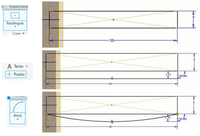
Then we eliminate the additional lines, the dimensions and the axes. With "line" we draw a perpendicular line in the middle of the roller profile and since we only need the middle of the profile to generate the hole for the mold, with the "Trim" command we eliminate the left half of the profile.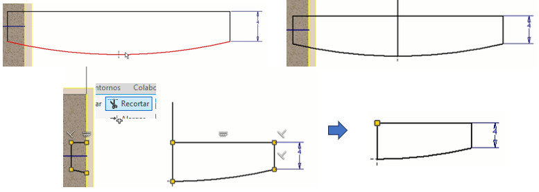
With the "Move" command we move half of the profile as shown in the figure on the left.
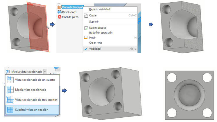
We will create a solid from the middle of the profile, to do this we create a line as the axis of revolution. We finish the Sketch and apply "Revolve" by selecting the figure and the axis respectively. And instead of adding we choose to subtract. Then we remove visibility of the plane that we created between two planes and see it in a full view by choosing the "delete section view" option.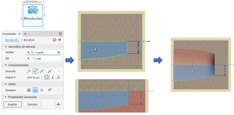
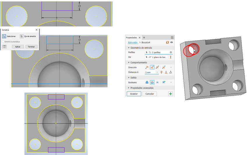
 On one face we create a sketch and in the middle we draw two circles, one 3mm in diameter (through this hole the silicone for the mold will be entered) and the other 2mm (hole for air outlet) in diameter as shown in the figure. We close the Sketch and make an extrusion but only up to the next face with a Boolean "cut" operation.
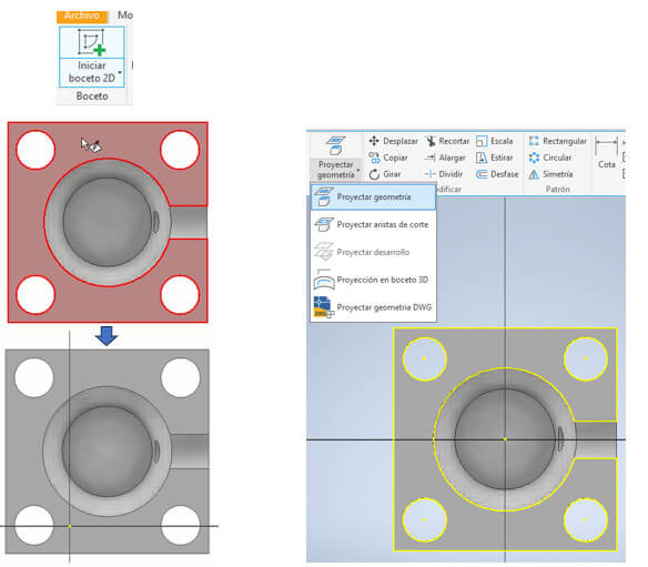
 We create another sketch on the upper face and project the geometry to have a reference for the 1.5 wide by 5mm long rectangle that we will draw (this will be used to separate the molds).
Then, using a mirror, we created the second one. Don't forget to create an axis of symmetry by drawing a horizontal line in the center. Once again we finalize the sketch and create a 3mm cutting extrude.
We can give color to the piece, select the entire piece, go to color, choose blue for the machinable wax, upload the color, select it again and enter. Mold A is ready.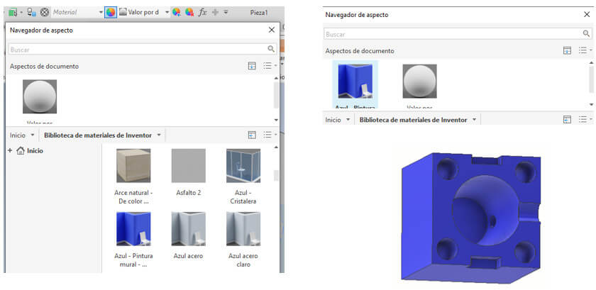
This mold is the same as the previous one, only the lower part has a 3mm diameter hole in the center. To do this, we create a sketch on the lower face, in the center we draw the 3mm circle and apply a cutting extrude that goes through the solid. And we already have mold B.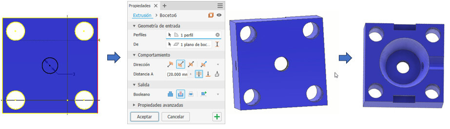
We start from the following image that we made for the first mold, we apply a 5mm extrude, then on the underside we create a sketch to be able to draw a 3mm circle which will have a 35mm extrude. We create the rectangles on the sides according to the steps seen for mold A (they are to be able to remove this piece), we can also give it color. The piece is ready.
This piece will be made by 3D resin printing as it is very fragile. This piece will generate the internal hole of the roller.
Now we must generate the stl files. Go to "Environments", click on "3D print", a part view is generated in a 3D printing space, then click on STL, put a name, save and that's it. Repeat for the other two pieces.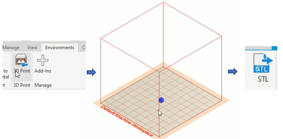
In the design it is important to take into account the following: When making moldings of curved surfaces at the end it will be necessary to give a finish to the part to obtain a smoother piece.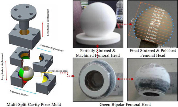 A demolding angle of 0.3 degrees has been considered in the design of the part so that the part does not adhere to the mold (Analysis in Inventor).
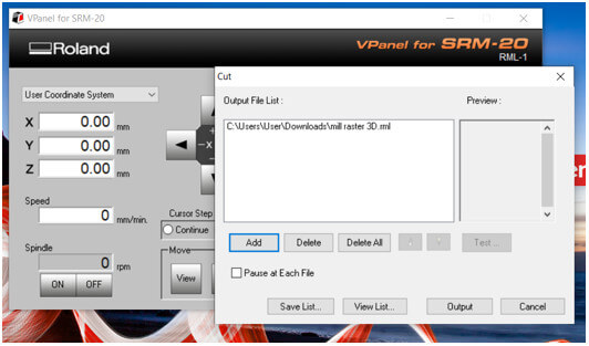
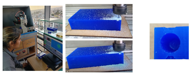
This time I will use the CNC Mini 3040 which is a desktop machine and its work area is 300mm x 400mm. Its operation is very similar to a CNC Router. This machine does not work with DSP but with the Mach4Loader software. Likewise, for it to work, I need to generate the GCODE file using RinoCAM.
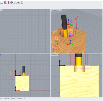
The process is very similar to what was developed in week 08, but there are some additional configurations that must be taken into account. We will work with a small piece, once the stl file is open, we configure dimensions with the "Box Stock" tool, align the design and establish the work zero as shown in the images. (The same procedure will be carried out for both molds.)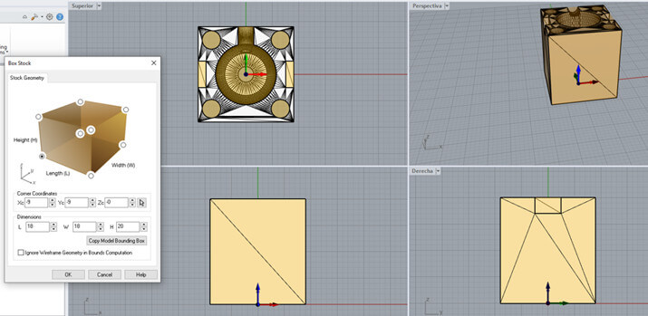

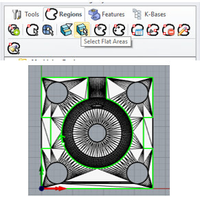
This time we will work in "3 Axis - Horizontal Roughing" and the 3 axis operations menu will be displayed.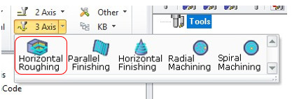
The “control geometry” tab is displayed first, allowing you to define driving or containment regions on 3 axes. This tab is basically used if you want to contain your tool path in a specific area of the part in three axes, if desired. Do not select anything from the control geometry tab, the entire part is used as a drive region. We chose the "Flat corn Mill" tool with a 3mm diameter and 5 flutes.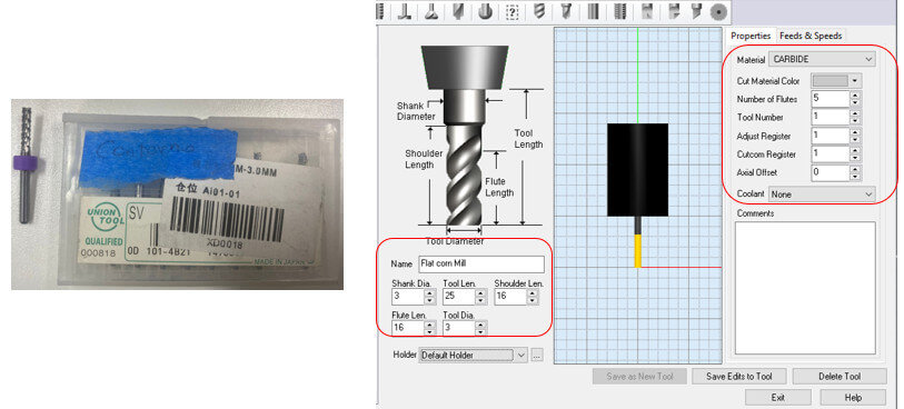
We configure the other options as shown in the images.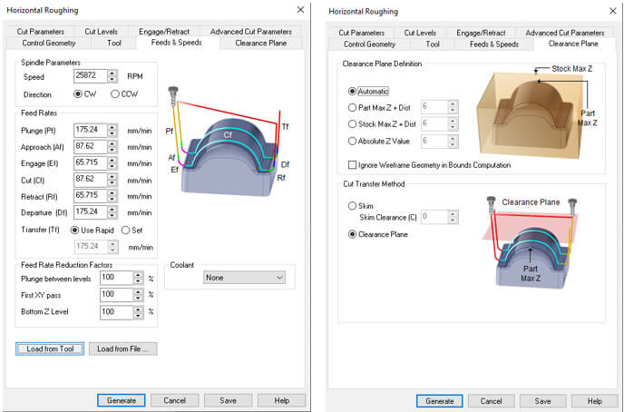

Then click Generate
It is important that the "Select Post-Processor" option for this CNC machine will be as shown in the image.
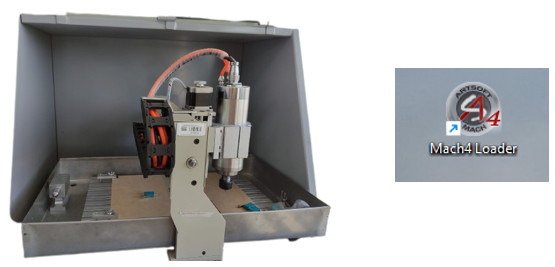
Open the program, select "Mach4Mill". And the work screen is displayed.
Click on the "Trace" tab and select the “Enable” option located at the bottom left of the screen.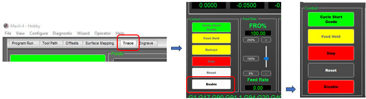 Go to "File" option "Open Gcode File" and select our file.
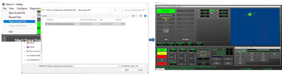 Before starting machining, the material must be securely fastened to the CNC work table, we place the bone with the coordinates in the lower left corner (using the arrows on the control panel) and we place the origin with the button “ Set Work – X Y Zero”.
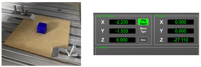 Then place the cutter as close to the material (while it is rotating, which is activated with the “Spindle CW / Stop” button, bring it closer to the material until you hear how it is drilled), once the Z coordinate is set, select put the Z at zero. Another way is to place a sheet of paper between the cutter and the material and bring the cutter closer until it rubs the paper, this is what I did.
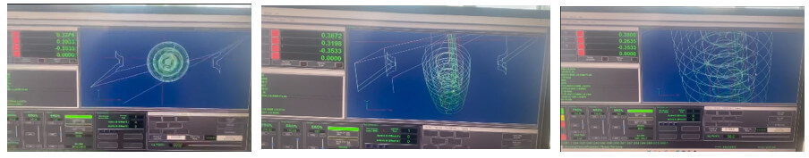
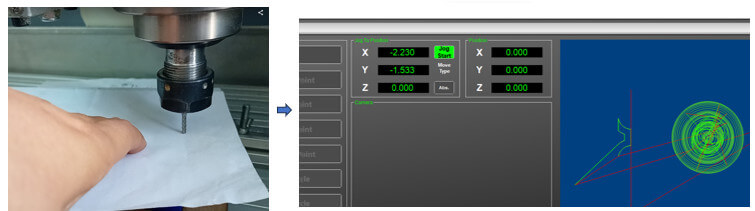 Once the zero points have been established, press the “Cycle Star Gcode” button, and the machining process will begin. For the other mold, the same procedure is carried out.
To achieve the internal hole that the roller must have, a third piece was made by 3D printing in resin (because it is a fragile). The other pieces were made with mechanizable wax.

On this occasion I will use Silicone RTV Y-805 to get the piece. This silicone is used to create prostheses identical to human skin since it is used to make body copies, has high flexibility and is dyed from the natural color of the skin. Mix Ratio Is: 1 Part A: 1 Part B By Volume.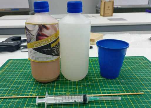
We proceed to perform the mixture.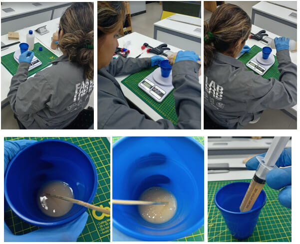
We place all the pieces and hold them well. To place the silicone I will use a syringe. Let's see how it turns out.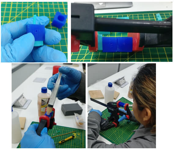
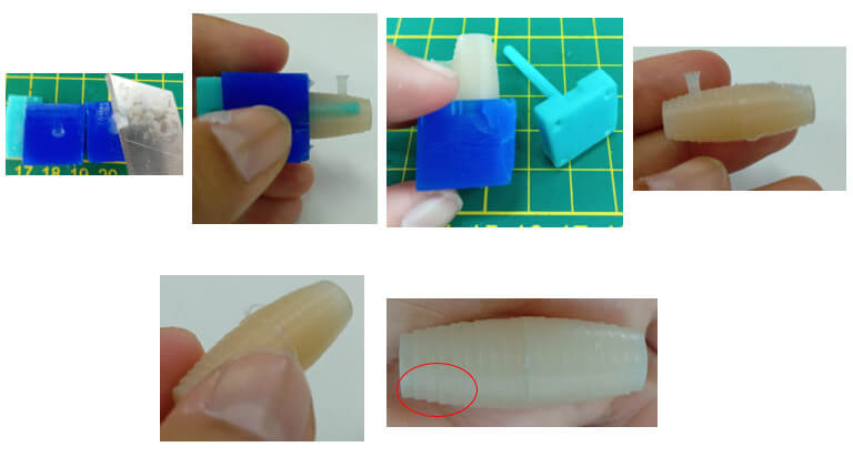
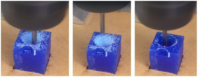
As you could see, the silicone wheel has some lines. These lines were formed in the machinable wax by the same machining process. Let's see how to improve it.
One way to give a better finish to the mold is to use a ball end mill, I will use a 1/8" and 4 flute one. Let's see how it turns out. I will make half the mold for the test, but this time I will apply another strategy, I will not cut the machinable wax into small pieces to machine. I designed a base to fix the machinable wax block and we followed the steps mentioned above.


Once the drying time is over, we remove the silicone mold, you can see a significant improvement.
Download the files here.


created with
Best Website Builder .