In this section we list the activities to be solved in the following table:
| Checklist | Estatus |
|---|---|
| Linked to the group assignment page | Finished |
| Documented how you designed your object (something big) | Finished |
| Documented how you made your CAM-toolpath | Finished |
| Documented how you made something BIG (setting up the machine, using fixings, testing joints, adjusting feeds and speeds, depth of cut, etc.) | Finished |
| Described problems and how you fixed them | Finished |
| Included your design files and 'hero shot' photos of final object | Finished |
- Complete your lab’s safety training
- Test runout, alignment, fixturing, speeds, feeds, materials and toolpaths for your machine
- Document your work to the group work page and reflect on your individual page what you learned
I will also do this assignment individually.
I worked with the following CNC router:
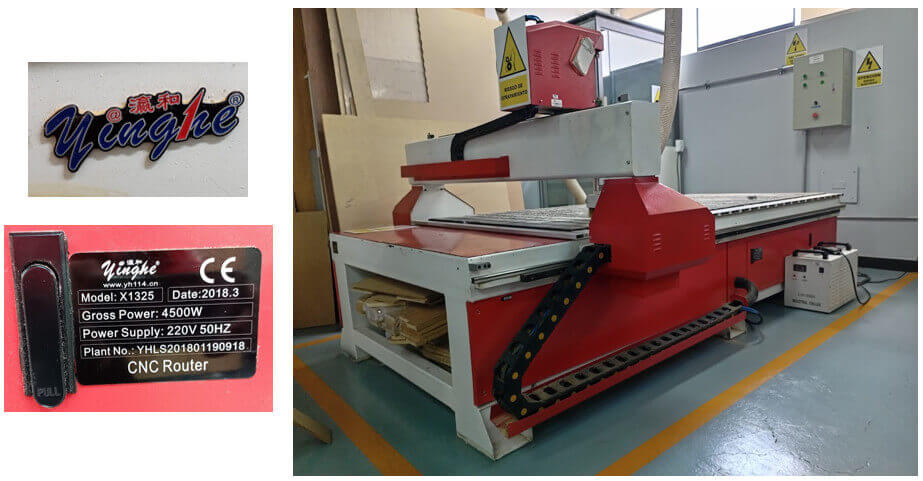

 The CNC router works together with a chiller for spindle cooling and a chip extractor to remove the residual material obtained after drilling or roughing work.
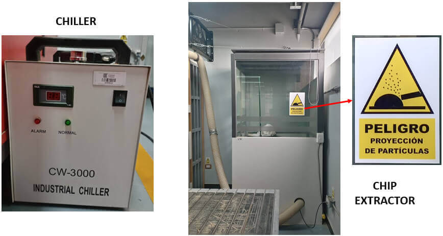
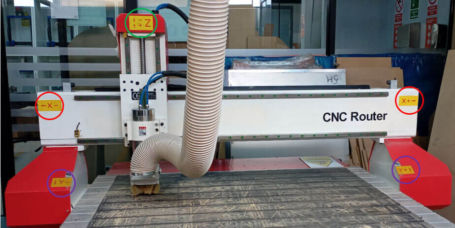
The CNC has stickers indicating the axis directions to facilitate the movement of the machine.
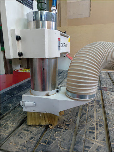
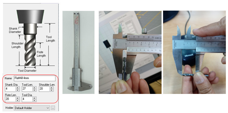
A large part of the success of the milling quality depends on the quality of the milling cutter. It is recommended to use solid carbide end mills to take advantage of the large number of uses they allow.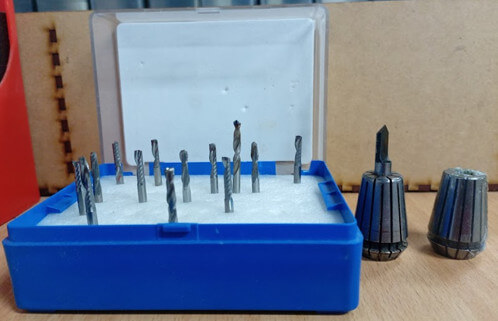 The image shows the bur I will be using for this assignment, it is a single flute cylindrical bur with a diameter of 4mm.
 With the appropriate tools, the drill bit to be used should be positioned; to do so, the chip extractor hose should be removed.
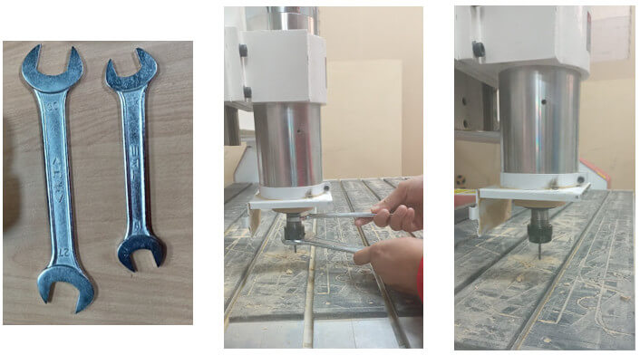
It is important to identify the control panel that governs the on and off of the CNC, chiller and extractor; as well as the emergency stop buttons. It is also important to know the precautions and places of risk in the handling of the machine.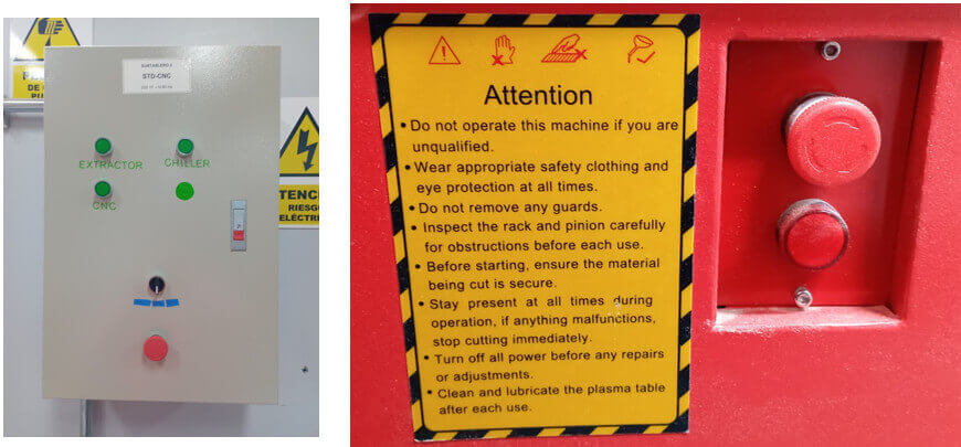
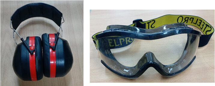
 Use appropriate protective equipment such as ear muffs and goggles.
For testing we will use 12mm mdf and 15mm plywood and I will use a single flute cylindrical mill with a diameter of 4 mm.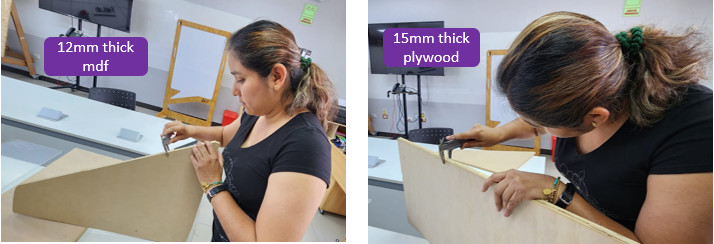
First test
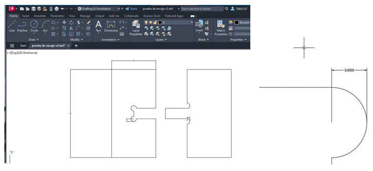
For my first test I will use 12 mm mdf and a single flute cylindrical mill with a diameter of 4 mm. I will make a test fitting using dog bone. In Autocad I make the design, using the command "line" I draw a 100x50 mm rectangle as shown in the figure; as the milling cutter is 4mm my instructor recommends me to make a first test with a 8mm circumference (it must be bigger than the diameter of the mill) using the Autocad command "circle" I place small circles of 8mm diameter in the corners where the pieces fit. With the "trim" command I remove the unwanted lines in the design. Once the design is finished, I export it in DXF format to be able to work on it in the Rhinoceros software and obtain the GCODE.
Open the Rhinoceros software and import the design file in DXF format and with the RhinoCAM extension the GCODE will be generated.

STEP 1: We open the program and create a new File. A new tab will appear to select a template. We choose the “Small Objects - Millimeters” template and click “Open” because it is a test design and the DXF file was designed in Millimeters. After configuring these parameters we import the dxf file. We place the part as close as possible to the coordinate origin, eliminate dimensions and we are ready to make the necessary configurations to obtain the GCODE.
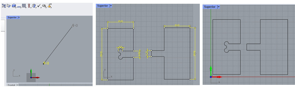 STEP 2: We configure the dimensions of the plate in the software with the "Box stock" tool, click on “Copy Model Bounding Box” and place "H = 12" (H - height), the height is the thickness of the material to be machined which in our case is 12mm thick MDF, then click on “OK”. Then we must align our design with the coordinate origin with the “Align Stock” tool, select “Top” and “South West” and click “ok”.
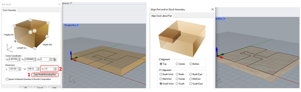
We must also align the WCS which stands for World Coordinate System and is used to define the location of geometric entities for those particular parts, assemblies or drawings. WCS is sometimes also called global coordinate system or absolute coordinate system. Select “Set to Stock Box”, “Highest Z” and finally “South West” and click “OK”.  STEP 3: We select the type of material to be used, in this case wood, with the “Material” tool. We select “WOOD” and click “OK”.
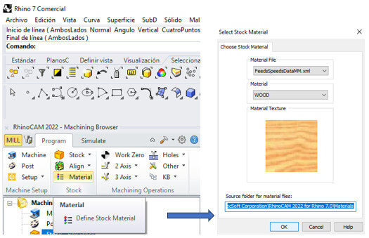 STEP 4: We must define where the machining will begin, in this case it will be at the origin with the “Work Zero” tool. Then select “Set to Stock Box”, “Highest Z” and finally “South West” and click on “Generate”.
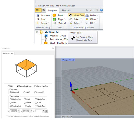 STEP 5: Now we will begin to program the machining operations. In this case there are two cutting operations, only the strategy is to cut the perimeter of the design with the two-axis tool “2 Axis - Profiling”. Manually select the perimeters that must be cut and press “ENTER”.
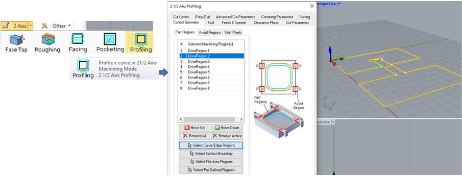
STEP 6: Define the tool in the “Tool” section; Double click on “Tools” and a new tab opens, select the second type of drill bit “Flat Mill” and place in “Tool diameter = 4”, “Shank diameter = 4” and “Number of Flutes = 1” then click in “Save as new tool” and “Exit”. STEP 7: Once the tool is defined, go to "Feeds & Speeds" to define the feed and speed parameters. Click on "Load from file" and it will load by default the pre-established values for the type of material to work with in our case "wood".
 STEP 8: In “Cut Parameters” specify that the drill bit must pass outside the perimeter. Activate the “Use Exterior/Interior for Closed Curve” box and specify “Outside”, the other parameters are left by default. In the “Entry/Exit” tab we select the “None” option in both options.
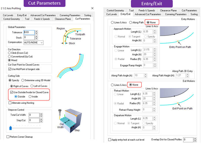 STEP 9: In the “Cut Levels” tab we select the thickness of the plate plus one millimeter to ensure the cut in “Total Cut Depth = 13” and the depth of the pass in “Rough Depth/Cut = 4” which must not exceed the diameter of the drill bit because it could break. After entering all the correct parameters, click "Generate". The operation is simulated to confirm that there are no errors in the programming.
 STEP 10: Finally we right click on “setup 1” and click on the “Publish” option, and we will save a “.nc” file that contains a GCode. It is advisable to save it on a USB and then transfer it to the CNC Router. A Notepad file will open with the ".nc" file.
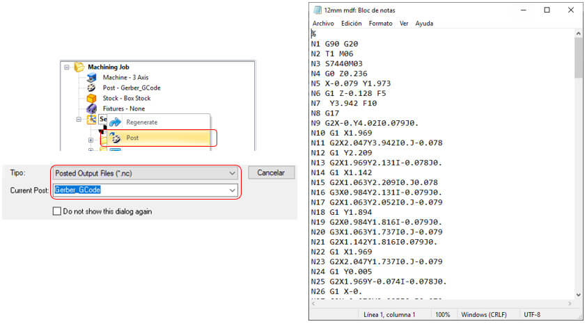
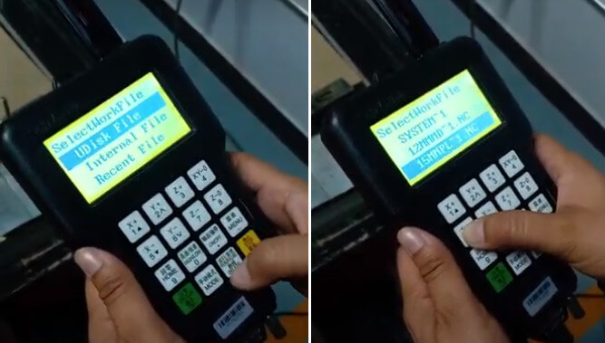
CNC routers are usually controlled with programs such as Mach3, NC Studio or similar, using a PC. But sometimes PCs are not used and a DSP controller is used to act as controllers. And one of the most used is the Richauto. Chinese CNC machines come with these types of controllers. These CNC controllers generally come with spindle and feed speeds configured so that every time you load a file you have to indicate those speeds on the controller itself.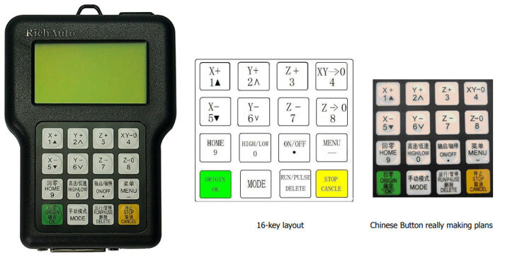
 Once the GCODE is generated, we save the file created with the ".nc" extension on a USB and then transfer it to the CNC router to proceed with the machining process.
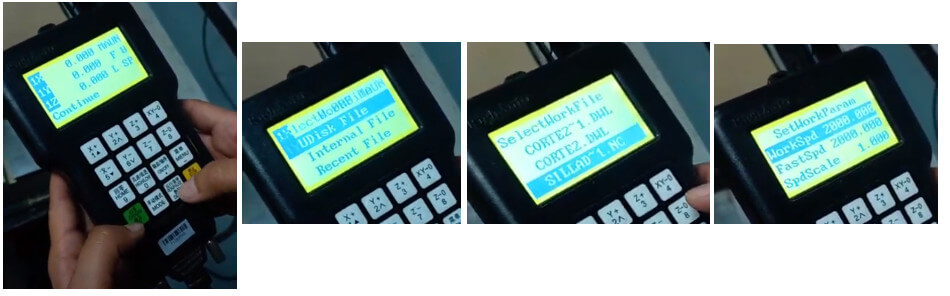
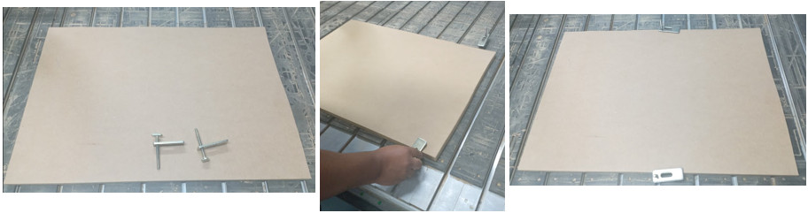
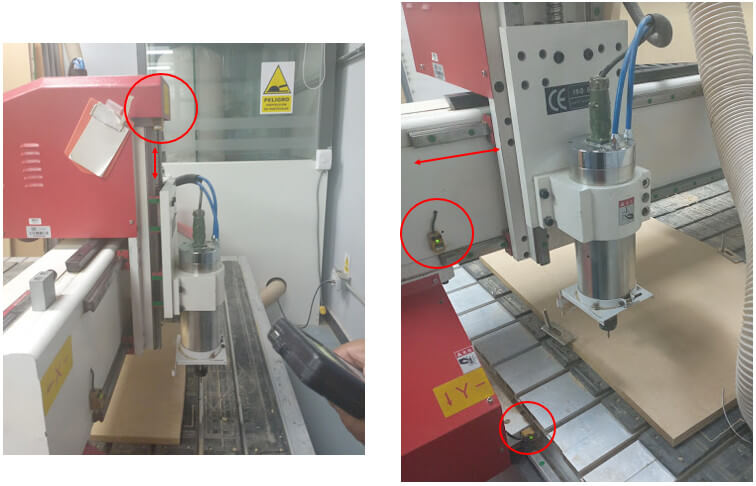
STEP 1: We fix the 12mm MDF to the work table, place the USB in the DSP and turn on the machine (put it in auto mode).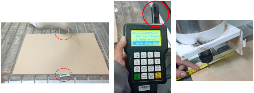
STEP 2: In the DSP menu, choose "None axis home" then with the movement keys, we move the head until we locate the point from where we will start working (zero point).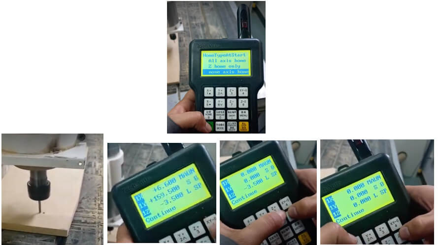
STEP 3: Located at the zero point, click on the "Run/Pause" key to enter and select the .nc file that contains our GCODE. We select the "12mm mdf" file, click "OK" and for the other messages click "OK". Note that the default values for the feed and speed parameters appear. The machine will start working.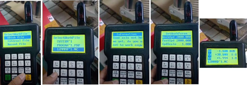
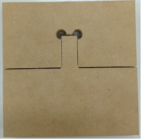
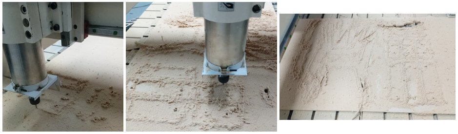
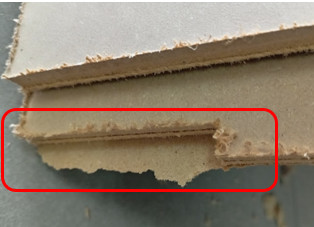
STEP 4: Once the cut is finished, we remove the burrs with a cutter and this is the final result.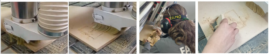
Second test
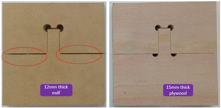
For my second test I will use 15mm plywood and the same router bit. I will modify the design by placing two more dog bones for a better fit and I will change the diameter of the circles to 6mm.
The parameter configuration process to generate the GCODE is very similar to what was developed previously, so I will only show the items that were modified. Don't forget that we continue working as the same milling cutter so the parameters for its configuration are the same.


In this section, the same steps are carried out as for cutting the 12mm MDF. Only this time we will work with the GCODE file for the 15mm plywood.

Final result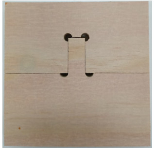
It can be seen that by adding the dog bones in the other piece of the design for the 15mm plywood, it presents a better fit than the 12mm MDF piece.
Make (design+mill+assemble) something big
CNC machining is a "subtractive" manufacturing process that often uses computer controls and machine tools to remove layers of material from a blank (or workpiece) and produce a custom part. In order to obtain a personalized part, a workflow must be followed that begins with the design of the part, generation of the GCODE (code that will be necessary for the machine to make the cuts), the preparation process of the machine, the machining process (cutting of the pieces) and finally the assembly of the pieces to obtain the final product.
Let's start with the design!
The furniture in a house is designed for adults, so when there are children all we do is try to accommodate them, so why not make furniture to fit the needs of a child?
The inspiration comes from Montessori furniture, which is small furniture for children that stimulates independence in the daily activities of a child from 2 to 5 years old. Montessori method furniture focuses on the philosophy of adapting spaces to children so that they are the ones who interact freely and safely with their environment, so that every step they take is a new learning experience for them.
After a search on the internet and seeing different models of furniture I decided to make a chair that meets the Montessori characteristics. Here is a reference.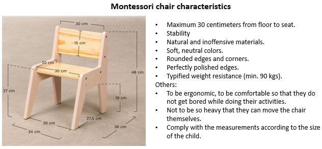
I will make the design in FREECAD and I will work with 10mm mdf and a 4mm milling cutter. When working with cnc we must be careful with the corners and the places where the pieces will be joined when assembling them; this is because the cutters have a circular shape due to the rotation, which makes it difficult to form a corner. That is why it is recommended to work with one of these options, I will use "T" Bone.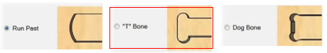
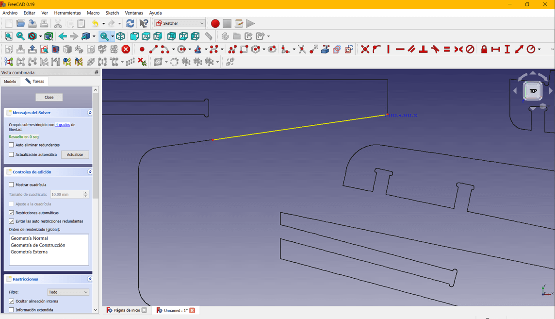
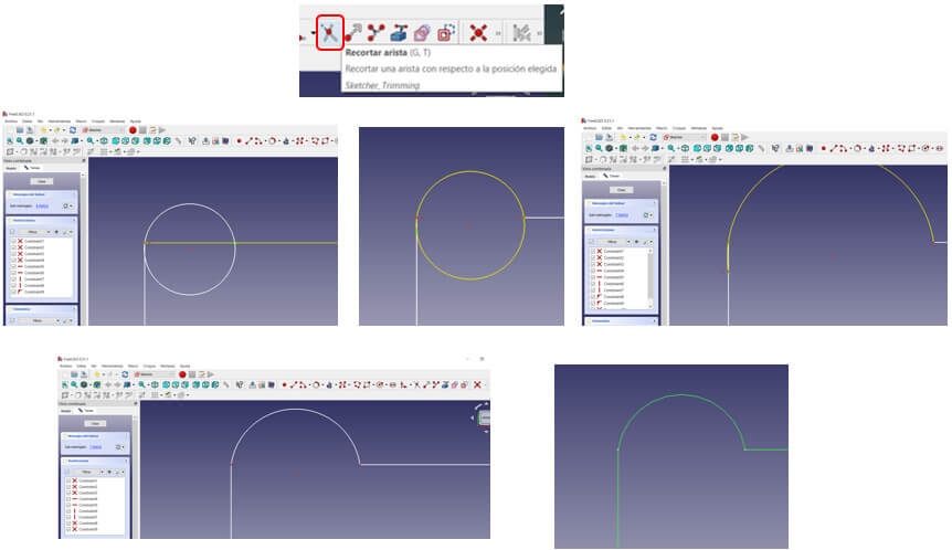
As the milling cutter cannot make 90° inside cuts, it is necessary to create these T-bones. As I don't have an option in the software to generate them automatically, I have to make them manually.
With the "circle" tool we create small circles in the corners; the radius of the circle depends on the diameter of the milling cutter we want to use, in my case I will use a 4mm milling cutter. My instructor tells me that the maximum circumference can be 6mm in diameter, I will try with that measure. Then with the "trim" tool we cut the excess and join the lines. That's it!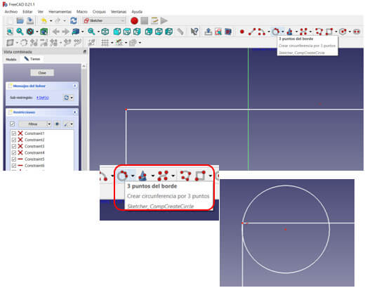
Taking into account the following measurements for a 2-year-old child, we will begin the design. I also considered a leg length of 240mm. In general, I will use the commands circle, polyline, arc, create fillet, trim an edge.
 I will start by making the sides that will be the bases for the backrest and the seat. The backrest will have a length of approximately 262mm considering the dimensions for the backrest sockets. And length of the chair legs from the seat approximately 242mm. I just make one piece and then I duplicate it. As a recommendation, to give it stability I will make two other pieces fit crosswise, so I will consider an opening between the legs of about 10.5mm wide (approximately the thickness of the material) and 130mm long.
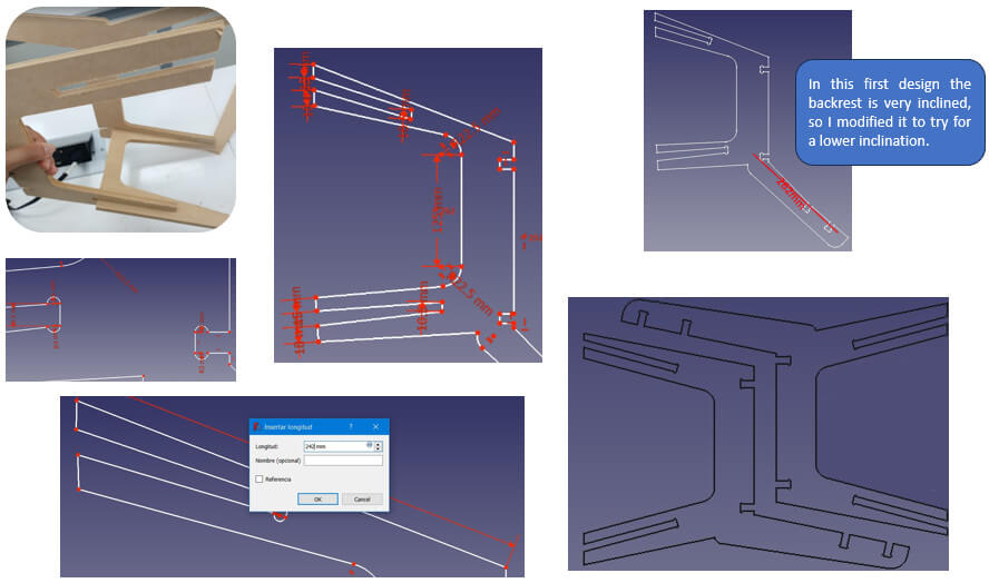 Next, I will make the pieces that will give more stability to the chair according to the measurements in the image, it will be enough to make one and then I will duplicate it. Here we must also take into account the radius of the Tbones.
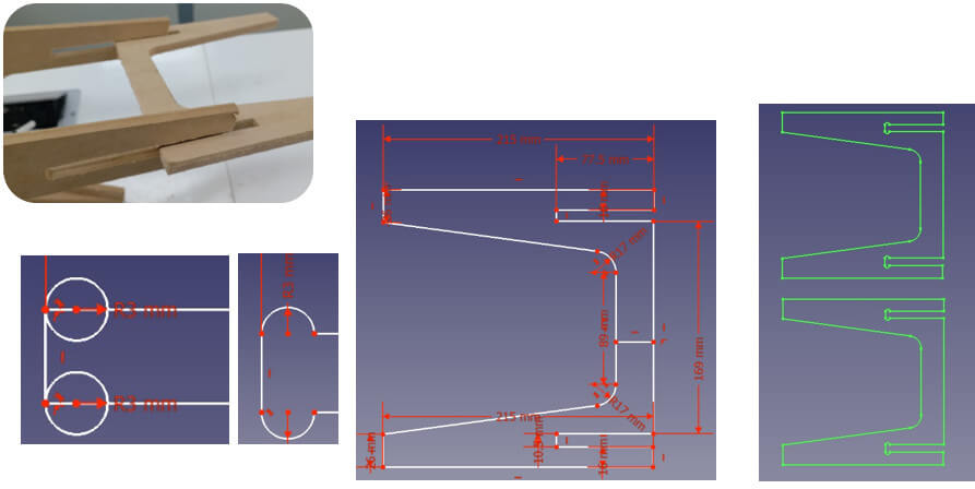
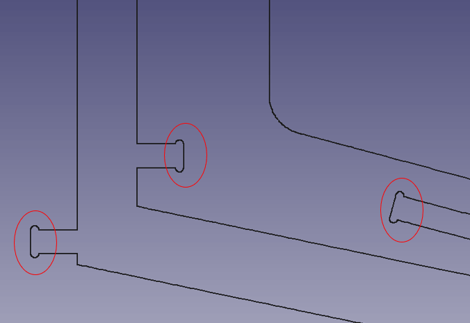
Now I will make the pieces that will support the seat and backrest pieces. These will have two slots to fit into the base of the chair and three protruding sockets where the seat and back pieces will be placed respectively. Here I must be careful to respect the thickness measurement of the material.
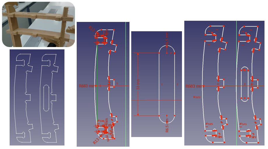 Now the pieces for the backrest. The back of the chair will be made up of three pieces, one rectangular and the other two in the shape of a trapezoid. Considering a width of 75 mm in each one, the rectangular piece will be 142mm long and a fillet of 6.5mm radius, the trapezoid-shaped pieces will be considered 142mm for the longest side and 127mm for the other. With the three pieces with a width of 75mm (75 x 3 = 225mm) I manage to cover the width of the back.
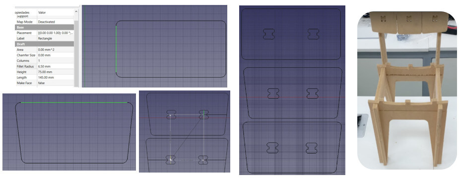 For the holes for the sockets I considered small rectangles 15mm long by 10mm wide (this depends on the thickness of the MDF) and the radii of the circumferences of 3mm (according to my instructor, a radius of 2.5mm would also work because it is still greater than the diameter of the milling cutter), as shown in the image.
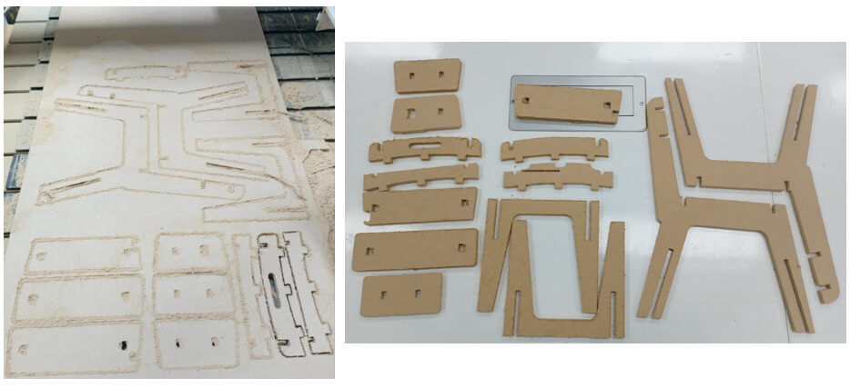
Finally, the seat pieces as shown in the images, I will use the same shape of the holes for the sockets as in the backrest, I use auxiliary lines to correctly locate the holes. According to the measurements we have approximately 210mm for the seat.
 Once the design is finalized, we organize the pieces to use the least possible material for cutting. Then we export the file in DXF format so we can take it to the Rhino software.
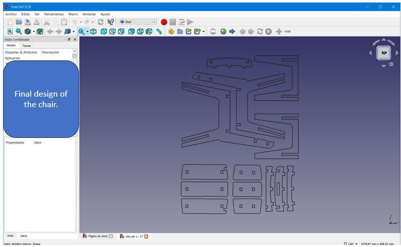
We will work with Rhinoceros and RhinoCAM software. In Rhinoceros we will open the design file in DXF format. I will use the RhinoCAM extension to manage the CNC equipment. All the steps carried out are detailed below:
STEP 1: We open the program and create a new File. STEP 2: A new tab will appear to select a template. We choose the template “Large objects - Millimeters” and click on “Open” because it is a considerably large chair for the size of a child and the DXF file was designed in Millimeters.
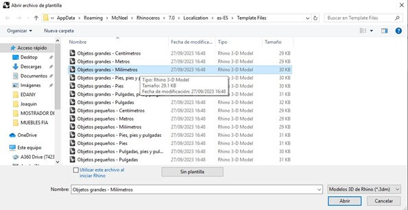 STEP 3: We import the DXF file in “File - Import”. And we select the file, in this case “CHILDREN'S CHAIR”. In the import options, leave the default options and click “Accept”.
 Taking into account the “Press-Fit” assembly type which is a type of snap-fit design for quick and easy assembly that eliminates the need for hardware and fasteners; We will have to check with the software the thickness of the plate with which the file to be cut is designed. The following images are of an example of this type of lace on a table.
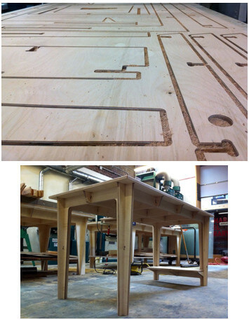 STEP 4: The check will be carried out with the "Line" tool. It can be seen from the design that it is a fit for a 10 millimeter thick plate.
 STEP 5: Once we have checked the thickness of the plate to be used, we configure its dimensions in the software with the "Box stock" tool. When clicked, the figure is selected in a perspective view.
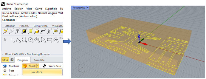 This Box Stock box also appears in which we must first select “Copy Model Bounding Box” and select the height (H - height), in this case the height is the thickness of the material to be machined, so we indicate that it is “H = 10” and finally click “OK”. In perspective we can see the result.
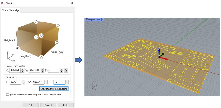 Then we must align our design with the coordinate origin with the “Align Stock” tool, select “Top” and “South West” and click “ok”.
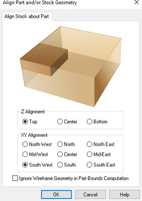 We must also align the WCS which stands for World Coordinate System and is used to define the location of geometric entities for those particular parts, assemblies or drawings. WCS is sometimes also called global coordinate system or absolute coordinate system.
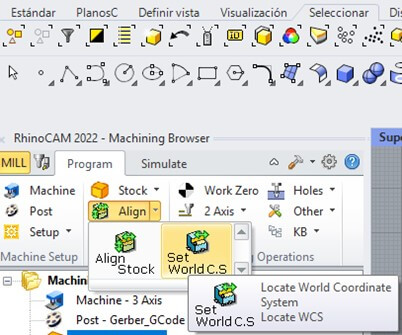 Select “Set to Stock Box”, “Highest Z” and finally “South West” and click “OK”.
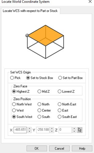 We verify that there is no offset in Z and everything is correctly aligned to the origin.
 STEP 6: We select the type of material to be used, in this case wood, with the “Material” tool. We select “WOOD” and click “OK”.
STEP 7: We must define where the machining will begin, in this case it will be at the origin with the “Work Zero” tool. Then select “Set to Stock Box”, “Highest Z” and finally “South West” and click on “Generate”.
STEP 6: We select the type of material to be used, in this case wood, with the “Material” tool. We select “WOOD” and click “OK”.
STEP 7: We must define where the machining will begin, in this case it will be at the origin with the “Work Zero” tool. Then select “Set to Stock Box”, “Highest Z” and finally “South West” and click on “Generate”.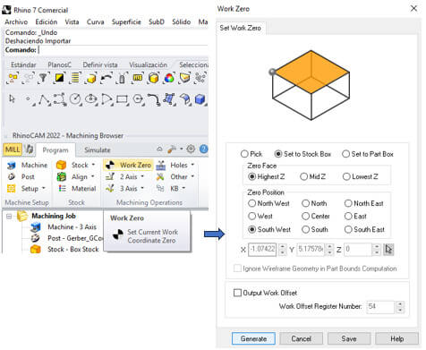 STEP 8: Now we will begin to program the machining operations. In this case there are two cutting operations, only the strategy is to cut the perimeter of the design with the two-axis tool “2 Axis - Profiling”.
 First Operation: Inside
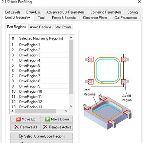
We select the geometry in the “Control Geometry” section, the “Select Curve/Edge Regions” option. Then, we manually strategically select the perimeters that must be cut inside and press the “ENTER” key. Later, when we reach the “Cut Parameters” section of the respective operations, it will be explained in greater detail why this strategy was chosen and finally it can be verified when the simulations of the operations are observed.
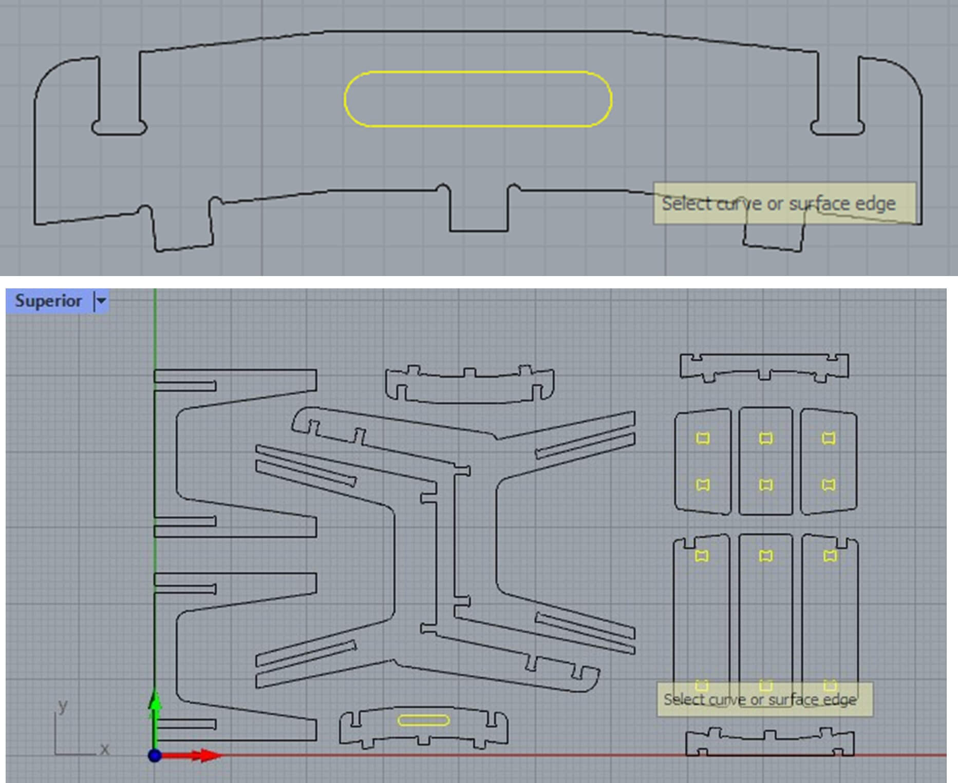 Now we must define the tool to use by looking for the “Tool” section, then double click on “Tools” and a new tab opens in which in this case we will use the second type of 4 millimeter drill bit, so we must select in “ Tool Diameter = 4” and “Shank Diameter = 4”, then we click on “Save as a New Tool” and finally “Exit”.
 Then in “Cut Parameters” we must specify that the drill bit must pass inside the perimeter to avoid eliminating parts of the piece that we need and that are part of the design. We select the “Use Outside/Inside for Closed Curve” box and specify “Inside”, the other parameters are left by default.
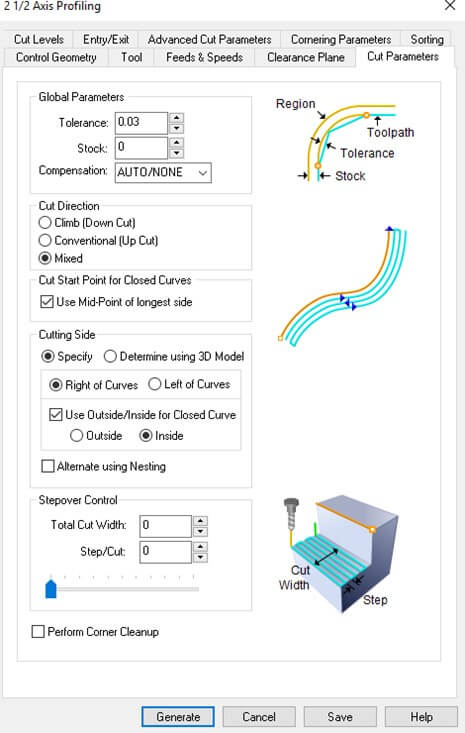
In the “Cut Levels” tab we select the thickness of the plate plus one millimeter to ensure the cut in “Total Cut Depth = 11” and the depth of the pass in “Rough Depth/Cut = 4” which must not exceed the diameter of the drill bit because it could break. In the “Entry/Exit” tab we select the “None” option in both options. Click on "Generate".
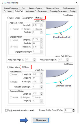 Finally, we proceed to simulate the operation to confirm that there are no errors in the programming. In the “Simulate” section, we click on “Play” so that the simulation is reproduced.
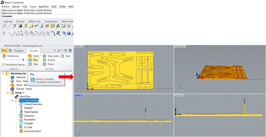 Second Operation: Outside
We select the geometry in the “Control Geometry” section, the “Select Curve/Edge Regions” option.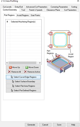 Strategically choose the geometries that are cut along the outer perimeter, since if they are cut on the inside we lose part of the piece that is part of the design.
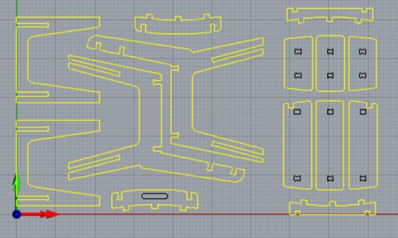
 In “Tool” nothing is selected, since it is only configured once. Unless later it was decided to change the drill bit or milling cutter, but in this case we will work with the same drill bit. You can even see the tool already saved with the name “FlatMill1".
In “Cut Parameters” we select the “Use Outside/Inside for Closed Curve” box and specify “Outside”, the other parameters are left by default.
The “Cut Levels” and the “Entry/Exit” section are configured in the same way as in the previous case. Click on “Generate”.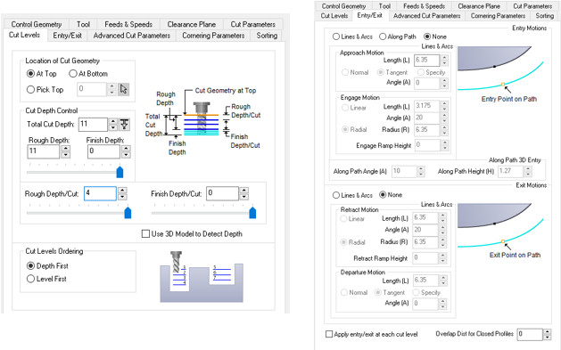 We wait for the operation to be generated.
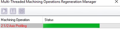 Finally we proceed to simulate the operation to confirm that there are no errors in the programming in the “Simulate” section. First we click on the two operations by pressing the control key and then we click on “Play”.
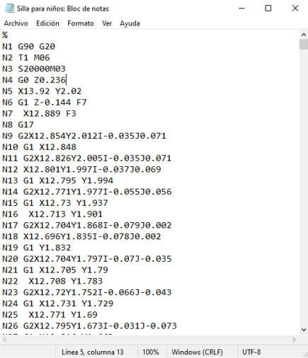
 STEP 9: Finally we right click on “setup 1” and click on the “Post” option, and we will save a “.nc” file that contains a GCode. It is advisable to save it on a USB and then transfer it to the CNC Router. A Notepad file will open with the ".nc" file.
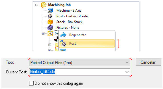
Once the Gcode is obtained, we can start with the machining. Once the GCODE is obtained we can begin machining. The steps are similar to those carried out for fit tests: hold the material to the work table, set the zero point, select the "child seat" file and that's it.
 Assembling the chair
When the machine has finished cutting, it is our turn to assemble the pieces. We remove the pieces, remove the excess and with the help of a rubber hammer we begin to assemble the chair.

Although we have worked with cutting parameters pre-established by the manufacturer and for wood material.
There is a very important formula with which you can establish the feed speed for different materials that relates the chip load (C), number of edges of the milling cutter (N) and the rotation speed of the tool in RPM. (S).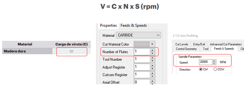
Whereas for wood:
Substituting into the formula we obtain V=2000 mm/min, which is what is established in the RichAuto CNC DSP Controller A11S.
These parameters are very important to carry out the cut correctly, if you want to know more you can consult this video.
Click here.


created with
Static Website Generators .