In this section we list the activities to be solved in the following table:
| Checklist | Estatus |
|---|---|
| Linked to the group assignment page | Finished |
| Documented what you have learned in electronics design | Finished |
| Explained problems and how you fixed them. | Finished |
| Included original design files (Eagle, KiCad, etc.) | Finished |
| Included a "hero shot" of your board | Finished |
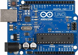
For this assignment we will use an Arduino Uno card to perform the measurements.
Step 1: We will use a BK PRECISION oscilloscope and a FLUKE 87 V multimeter to make the measurements.
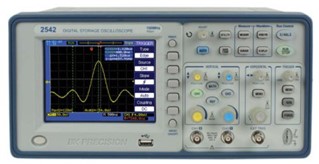
Oscilloscope BK PRECISION

Multimeter FLUKE 87 V
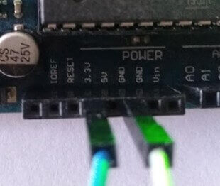
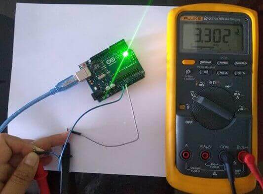
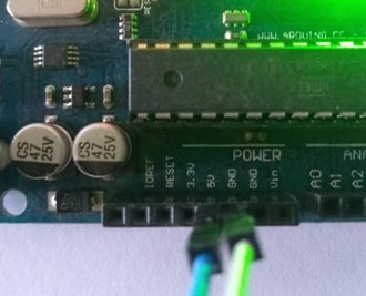
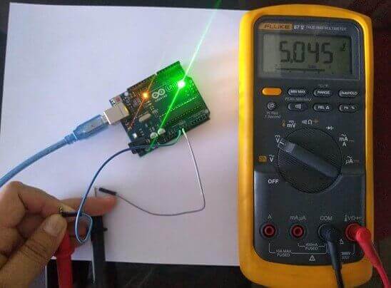
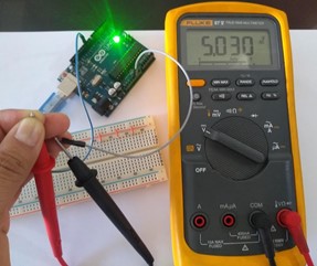
Step 2: We proceed to measure the exit voltages which are respectively 3.3V and 5V; in the multimeter the corresponding values of 3.302V and 5.045V can be seen, voltages that coincide with what is indicated on the Arduino Uno card.
3.3V VOLTAGE
5V VOLTAGE
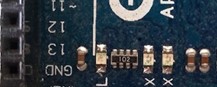
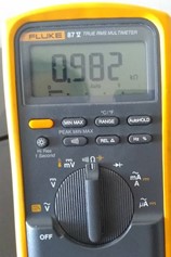
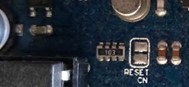
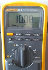
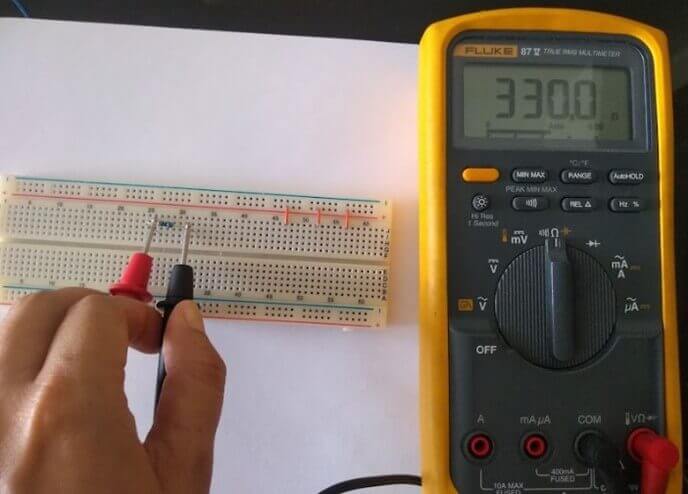
Step 3: Now we set the selector of the multimeter to ohms and means the SMD resistors of 102 (4 x 1KΩ) and 103 (4 x 10KΩ). With the multimeter the following resistance values are obtained, respectively 0.982KΩ and 10.08KΩ, which are very close to those indicated on the Arduino Uno board.
Measuring resistance 102 SMD (4 x 1KΩ)
Mesuring resistance 103SMD (4 x 10KΩ)
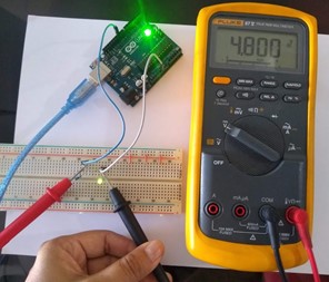
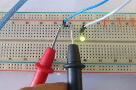
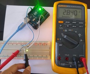
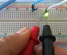
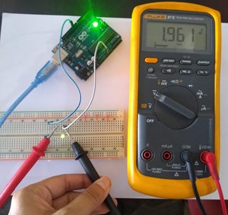
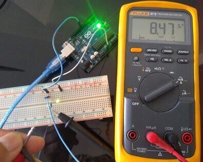
Step 4: Measure the output voltage of a digital pin, for this the Arduino board has been programmed to activate a led connected to pin 10, we build the small circuit with a 330 Ω resistor and a green led.
The following measurements were made:
Step 5: Using the oscilloscope, visualize the waveform of a flashing LED connected to pin 13 of the Arduino which already contains an internal resistance, for this the card has been previously programmed. The waveform is square and each square is 1V, as can be seen in the first video.
In the second video, the variation of the voltage is observed when the LED blinks. On the voltage is 4.784V and off 0V.
Step 6: With the oscilloscope, we can see the behavior of a pin with PWM output. In the first video you can see how the intensity of light in the LED varies. In the second video you can see how the width of the output pulse varies. And in the last one, as this variation of the width of the pulse, it is reflected in the variation of the output voltage and the voltage in the led. It is shown that by varying the pulse width of the output signal, the voltage varies causing the led to shine with greater or lesser intensity.
Step 7: We place the tips of the oscilloscope on the Tx and GND pins and observe the behavior of the signal when uploading a program to the Arduino board. We repeat the procedure, but this time with the Rx and GND pins. It is observed in both cases that when a program is loaded on the card there are variations in the signal, which shows that the data is being sent correctly.
For this assignment I decided to use EasyEDA, this is a PCB design and circuit simulation software, its use is completely online and free, it does not require installation; the only thing we have to do is register to be able to access all the benefits of this software. We have two options: (1) create our account or (2) log in with Google.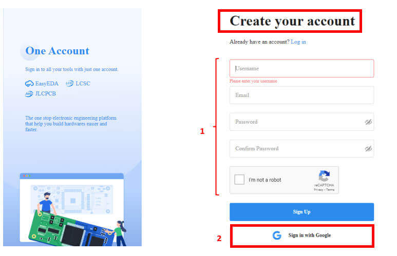
Once registered, the following screen should appear: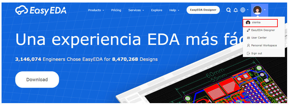
To start, enter the standard online editor.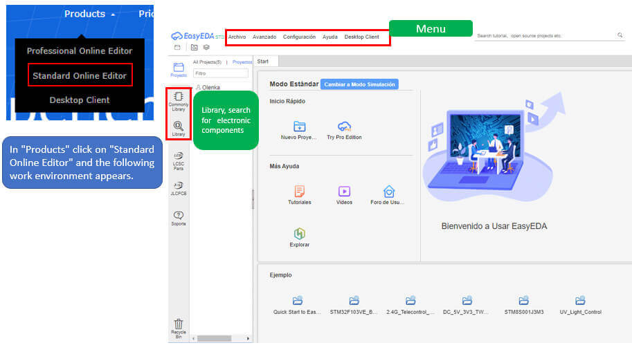 Once there we created our first project.
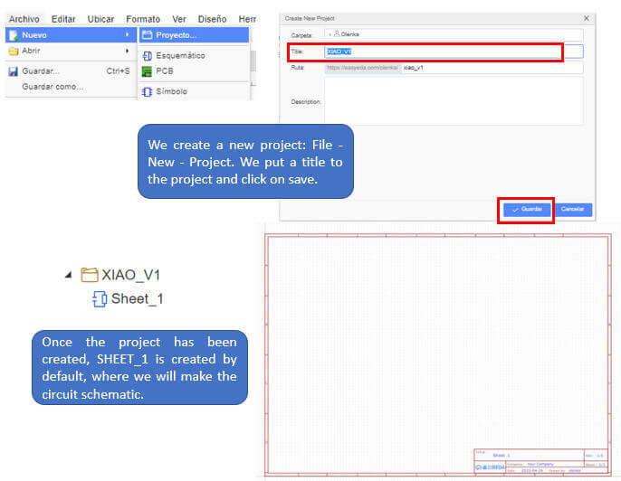
To enter the electronic components for the circuit we have two options: “Commonly Library” and “Library”. The first shows us the most used basic electronic components and the second allows us to search for components that are not found within the basic components and that have been created by third parties.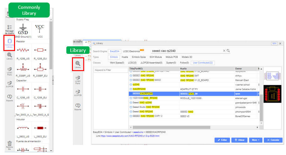
XIAO RP2040 is a microcontroller using the Raspberry Pi RP2040 chip. It supports multiple languages, including C/MicroPython/CircuitPython.
To know more about this microcontroller click here. Knowing the pins it presents allows you to properly connect the components. Here is your pinout.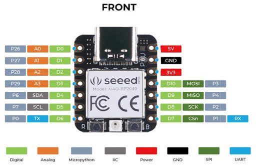
Now we proceed to create our circuit, I took as a basis what was done by Adrián Torres and started with the design. With the help of the libraries we first entered the SEEED RP2040 and then the rest of the components.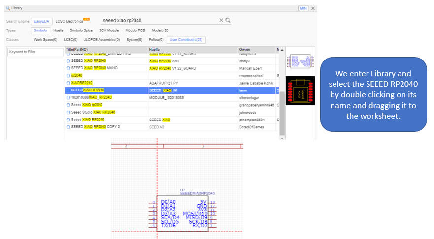
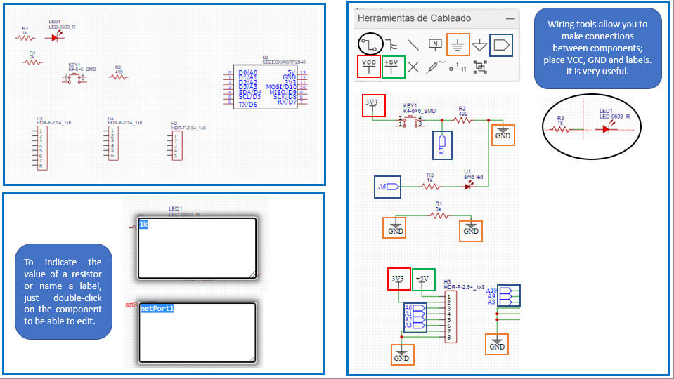
Once all the connections are made, the circuit should look like this: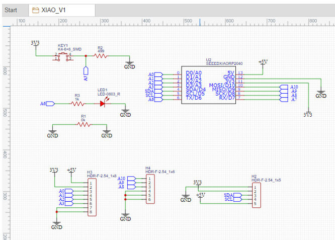
The next step is to design the circuit PCB.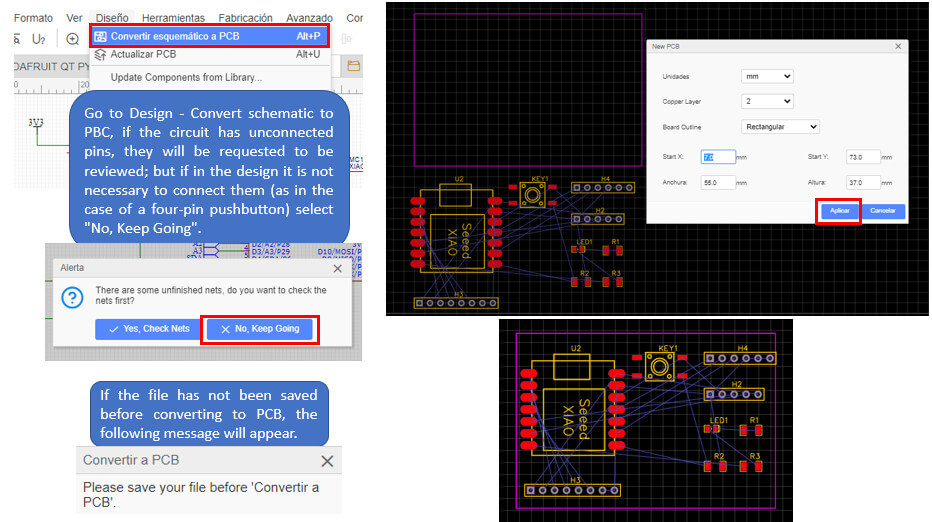
We order the components to be able to route the tracks. I use Auto Routing first to help route the tracks, auto routing is not always the most convenient, let's see how my PCB looks.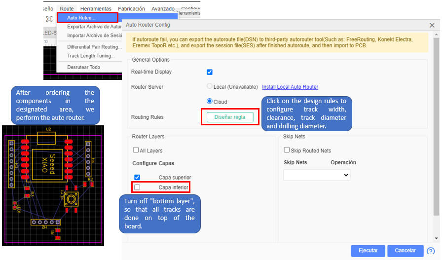
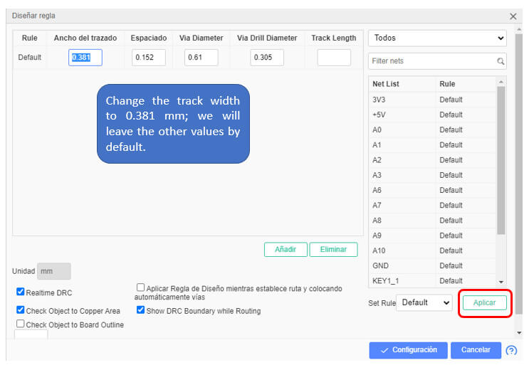
After Auto Routing, only three tracks failed, so I did them manually.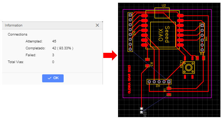
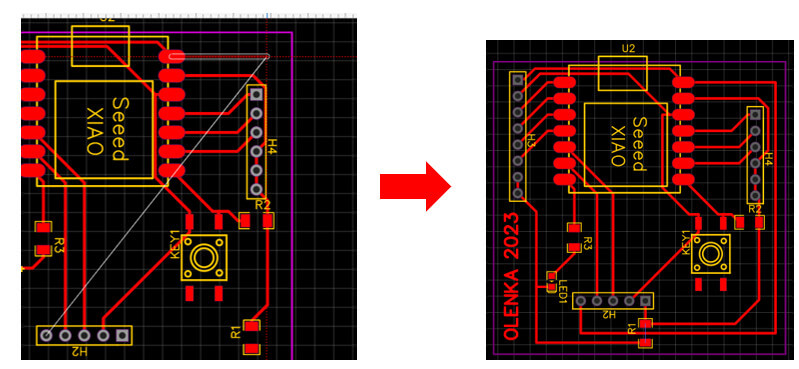
The PCB is ready.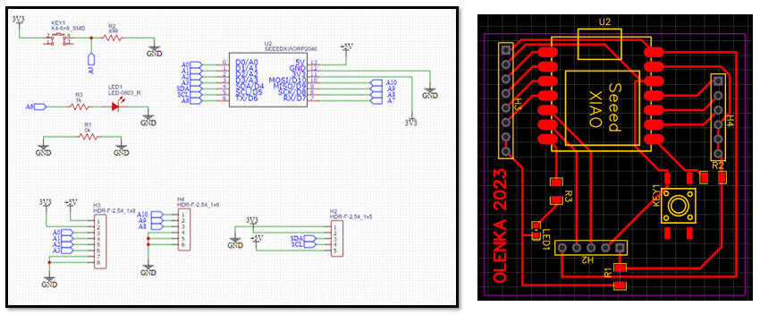
Finally, we can see what our design will look like by generating a 3D view.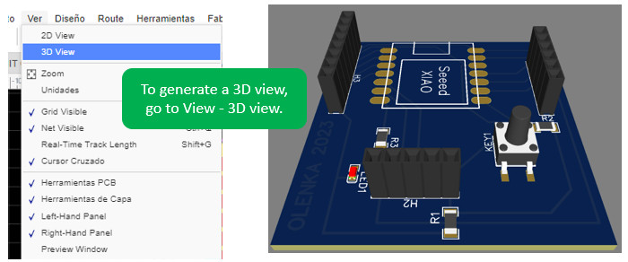
1. A background in electronics facilitates circuit schematic design (connecting the electronic components of a circuit).
2. It is important to identify the function of each pin of the microcontroller, to correctly make the connections and a better distribution of the circuit components.
3. Not all component footprints are best suited for the design. At first I chose the print that is shown in the image, in the schematic there was no problem; When trying to perform manual routing, that footprint did not allow me to make connections below the XIAORP2040, so I had to change it. In the same way I had to change the footprint of the led.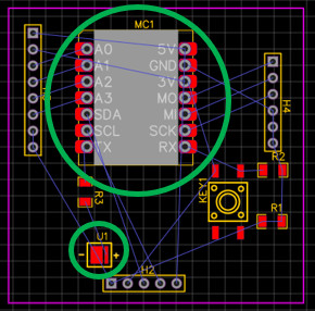
created with
Website Builder Software .