In this section we list the activities to be solved in the following table:
| Checklist | Estatus |
|---|---|
| Linked to the group assignment page | |
| Explained what you learned from testing the 3D printers | |
| Documented how you designed and made your object and explained why it could not be easily made subtractively | |
| Documented how you scanned and prepared an object (for 3D printing) | |
| Included your original design files for 3D printing (both CAD and common format for 3D printing) | |
| Included your hero shots |

3D printing, also called aggregate manufacturing (English), is a set of processes that produce objects through the addition of material in layers that correspond to the successive cross sections of a 3D model.
3D printing allows us to create prototypes and mass manufacture; It is also a technology that allows complex geometries to be created that were previously not possible with other manufacturing processes.

Test the design rules for your 3D printer(s)
Document your work and explain what are the limits of your printer(s) (in a group or individually)
Document your work to the group work page and reflect on your individual page what you learned.

To carry out our 3D printing work we use a Brand printer: CREALITY whose model is ENDER 6 whose characteristics are:
• Type: FDM or FFF. 3D printers using FDM technology create parts layer by layer from bottom to top by heating and extruding thermoplastic filament.
• Mechanism: XY-Z Corexy

• Printing Area: 25x25x40cm
• Resolution: 0.08mm - 0.3mm
• Accuracy: +/- 0.1mm
• Speed: ≤150mm/s
• Recommended working time: ≤100h
• Number of Nozzles: 1
• Nozzle outlet diameter: 0.4mm
• Filament Diameter: 1.75mm
• Materials: PLA, ABS, PETG, Wood, TPU*
• LCD touch screen: Yes
• Filament Detector: Yes
• Print recovery after power failure: Yes
• Arming time: 50 minutes
• Prints flexible filament: Yes*
• Includes Filament: Yes, 200g
• Connectivity: MicroUSB
• SD card: Yes
• Electrical input: AC 100-265V 50-60Hz
• Electrical output: 360 W 24 V
• Size in box: 63x54x41cm
• Weight in box: 26.5kg
Here are some pictures of the machine:

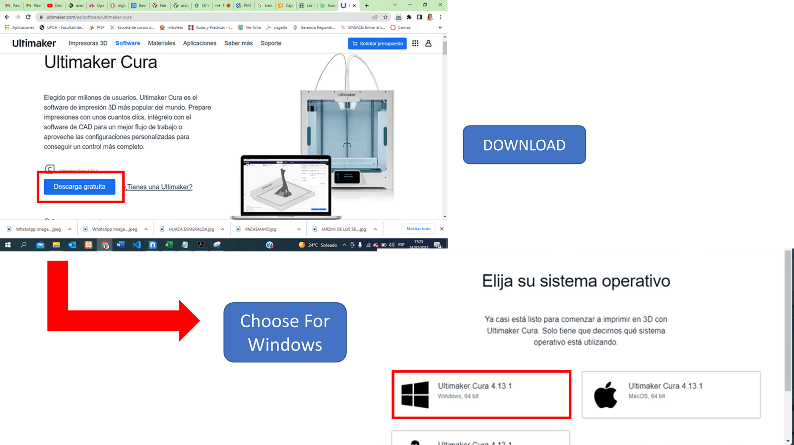
Ultimaker Cura 4.13.1 is a 3D printing software used not only by Ultimaker but also by printers from other manufacturers; the formats supported by this software are STL, OBJ, X3D and 3MF. It is free software and it is available in more than 15 languages which makes it easy to use.
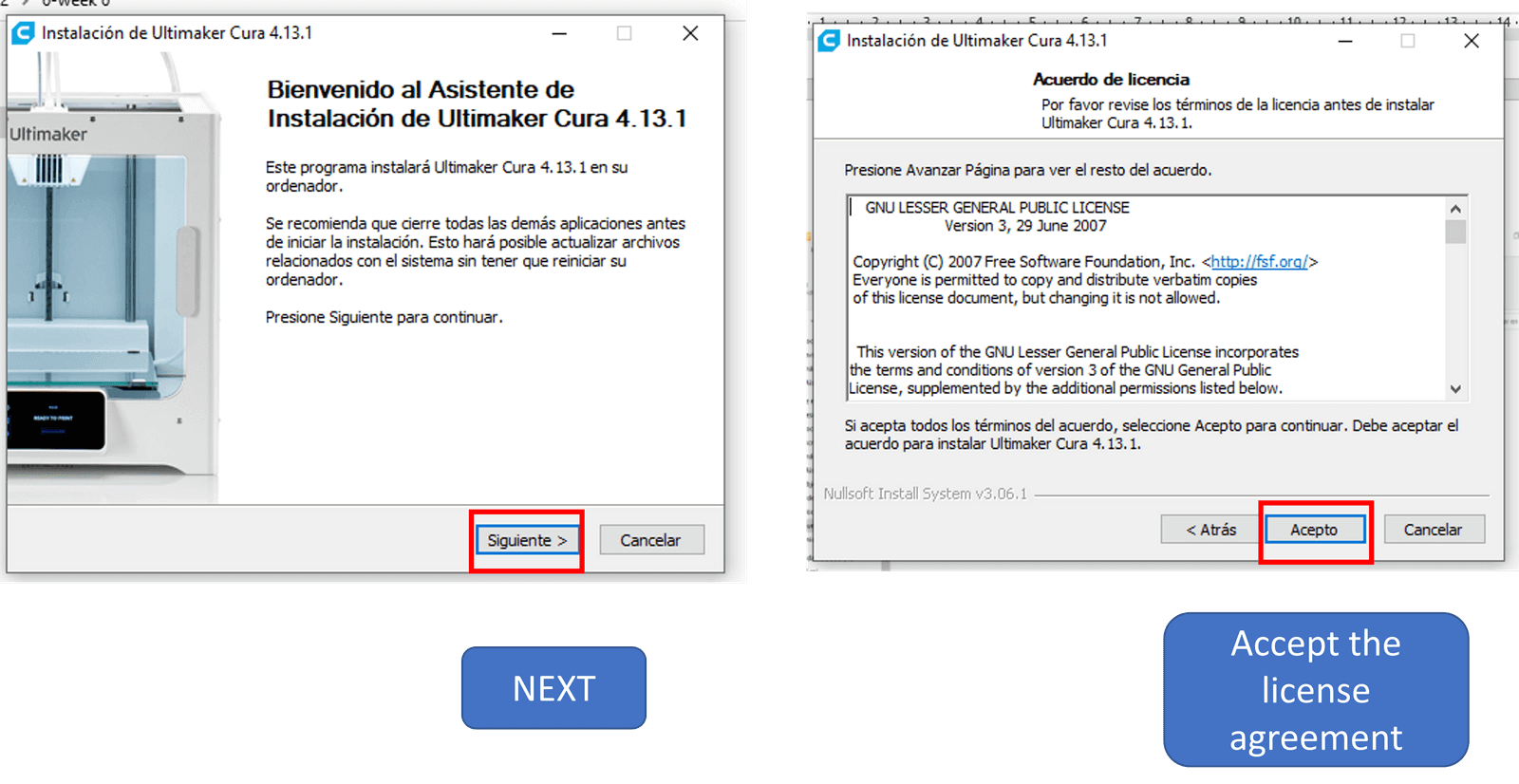
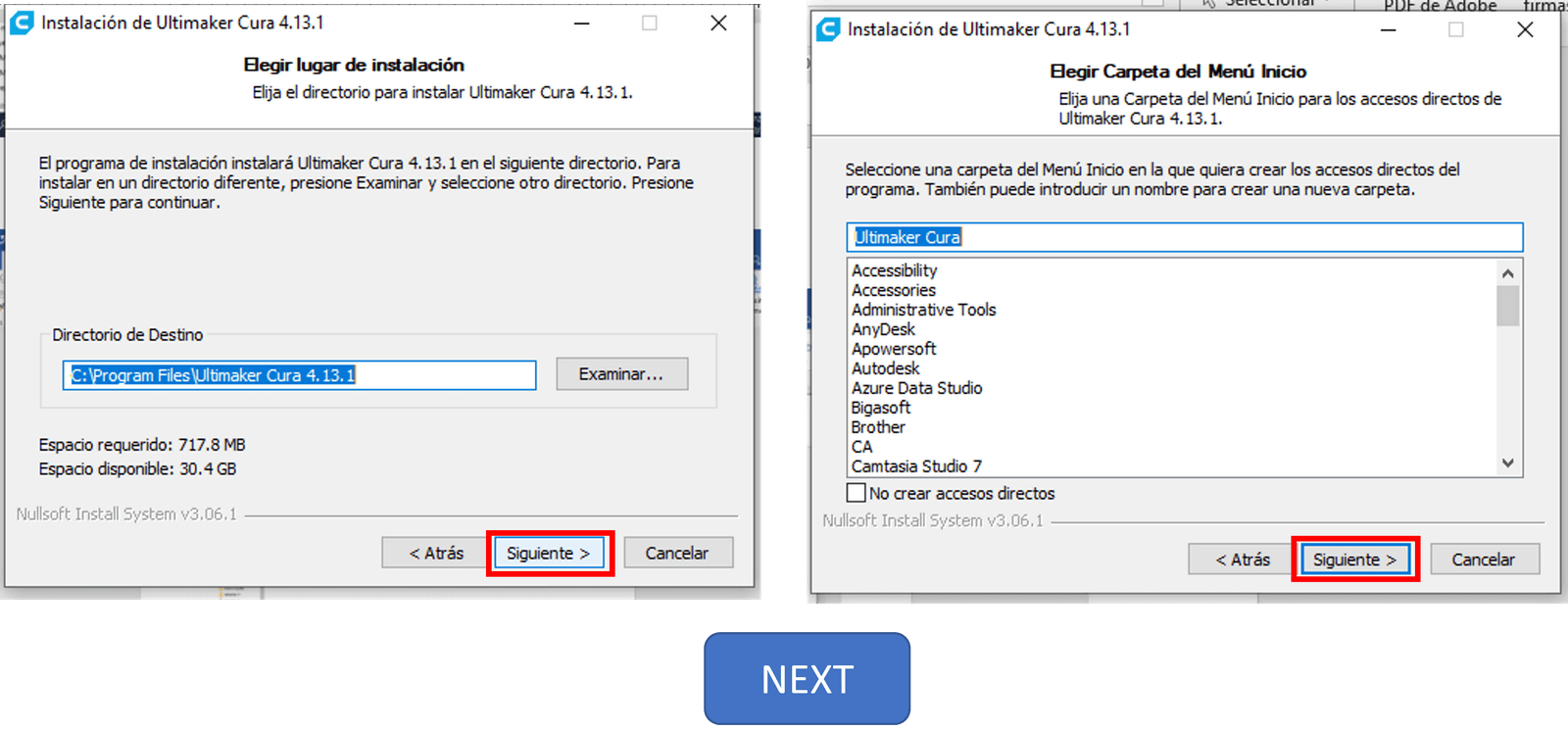
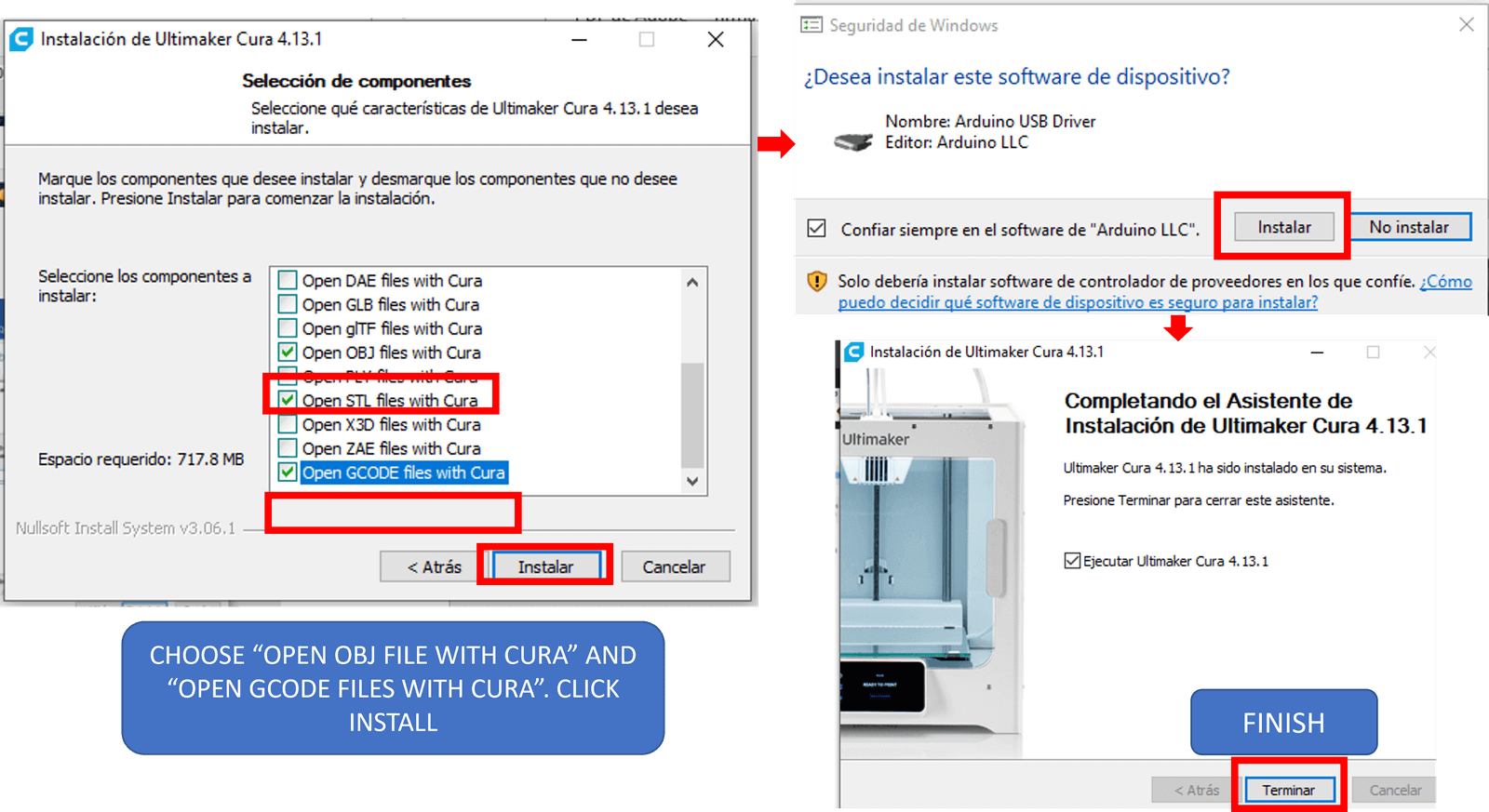
We download and install the software as shown below.
Remember
STL format:
is the standard data transmission format par excellence of the rapid
prototyping industry.
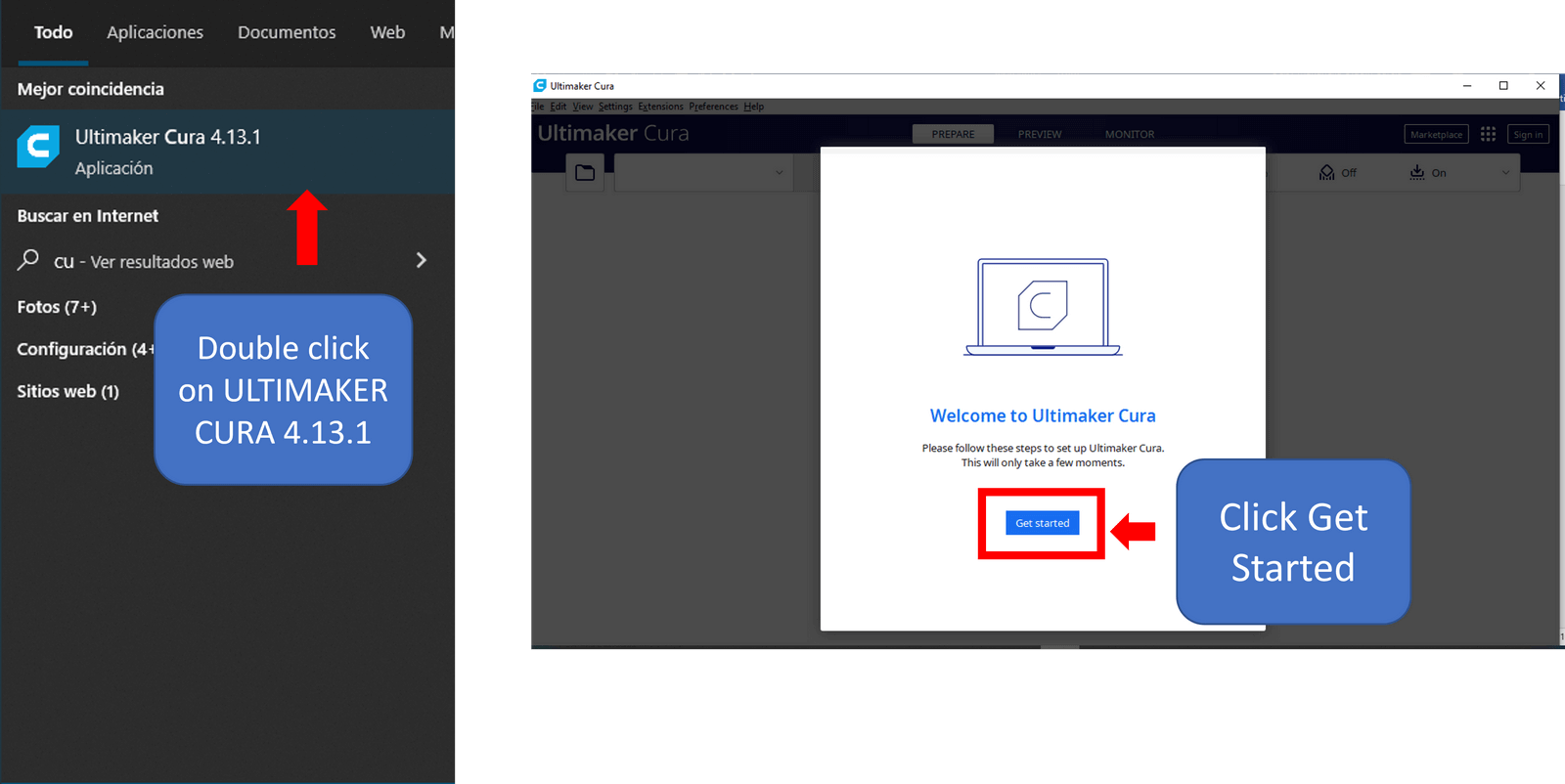
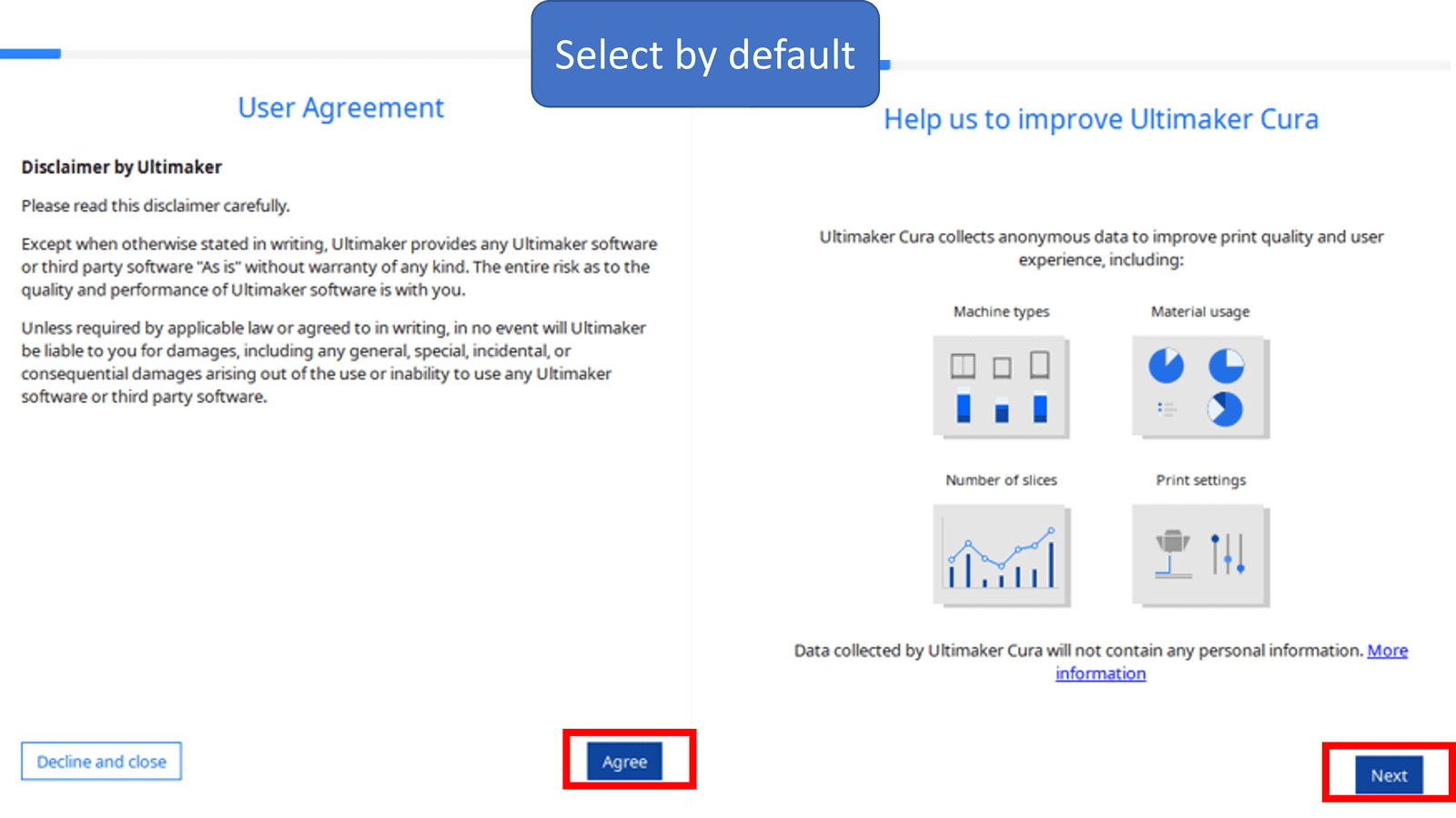
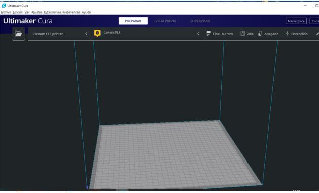
Once installed, we open the program; The first thing we must do is choose the type of printer to use, in this case we select ULTIMAKER S5.

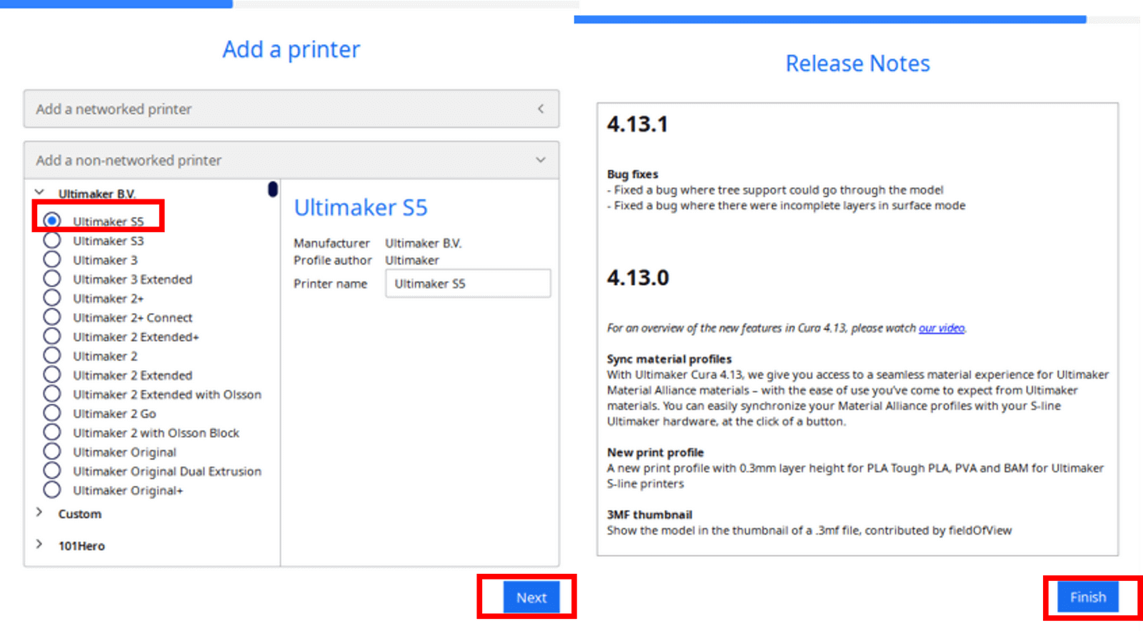
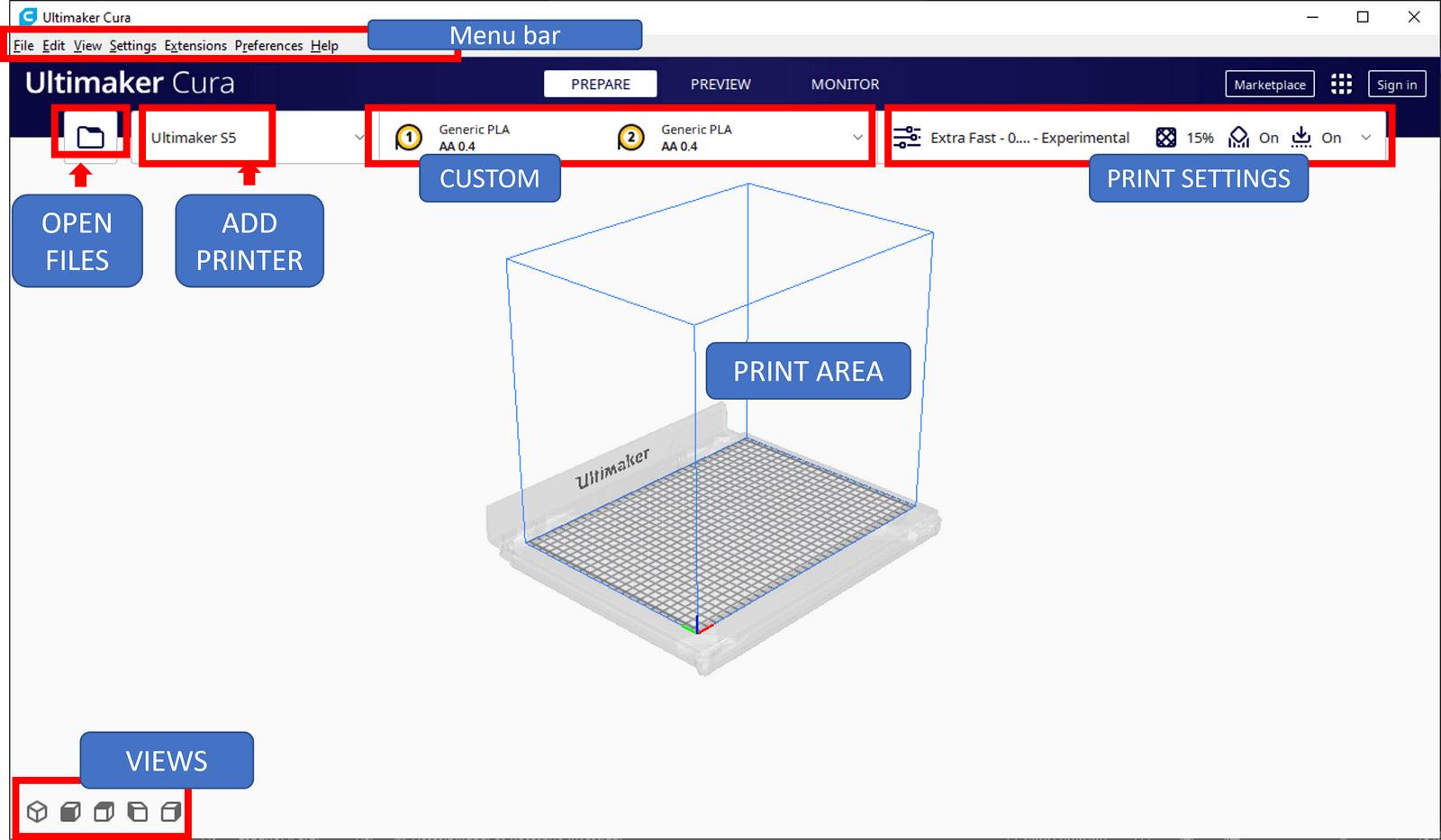
At the end, it presents us with the following environment:
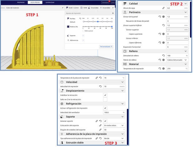
To carry out the tests corresponding to the design rules, we resorted to the Ultimaker Cura 4.13.1 Software, since we do not have the availability of a printer, we chose to simulate the result of the 3D printing of a part under different parameters using this software.
We downloaded a piece to do the design tests ”3D_printer_test_mini”, the link can be found here.
Downloaded the piece we open it from the Cura.


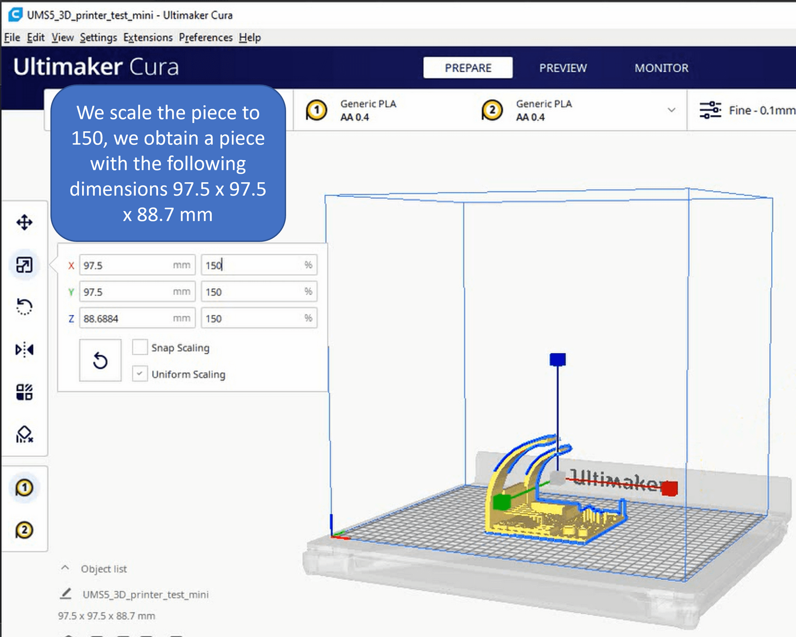

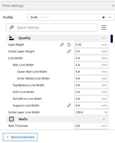
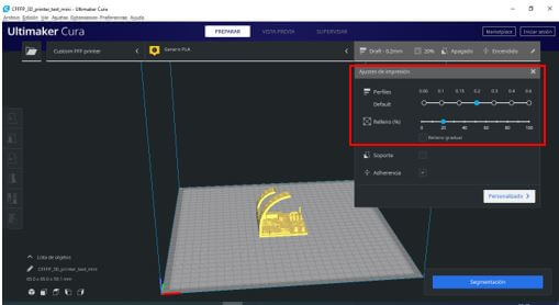
We perform the first test with the settings shown and the following is obtained:

Now we modify the angle of rotation, but keep the same settings. You can see how the printing time and the material used vary.

Now we will modify the profile to 0.1, keeping the other options the same.

What did we learn:
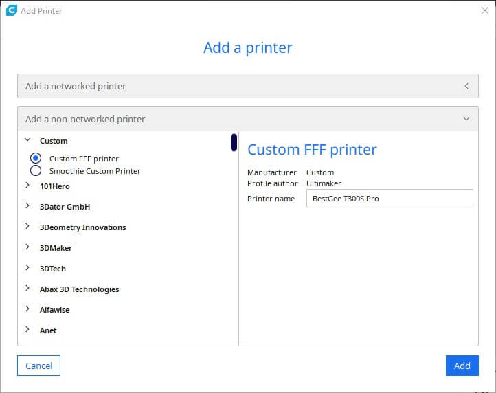
We open the image to work with in Ultimaker CURA, which is a program that allows us to do slicing (convert a 3D object to a printable object by transforming it into layers, that is, in GCODE code). When entering CURA for the first time, it asks us to choose a printer. In our case, it is the 3D BESTGEE T300S PRO, but since we entered it for the first time, we chose the CUSTOM option.
 We open the image to work with in Ultimaker CURA, which is a program that allows us to do slicing (convert a 3D object to a printable object by transforming it into layers, that is, in GCODE code). When entering CURA for the first time, it asks us to choose a printer. In our case, it is the 3D BESTGEE T300S PRO, but since we entered it for the first time, we chose the CUSTOM option.
The values of the X, Y and Z axes of the first column are changed with the values of 300, 300 and 400 as measured and as we can see in the video.

We configure the extruder with the following values where the first value corresponds to the size of the nozzle and the second the diameter of the material to be used (PLA) that we can find in the printer specifications:
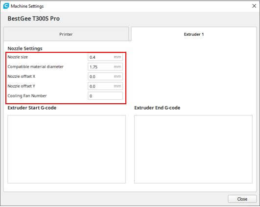
The same nozzle also indicates the size:

Being in the ultimaker we can change certain characteristics of the software for this we enter the settings menu --- Configure settings visibility --- General where we can change the language and theme of the interface.
NOTE: The Ultimaker Cura software allows you to later add another printer via the menu SETTINGS - PRINTER - ADD PRINTER.
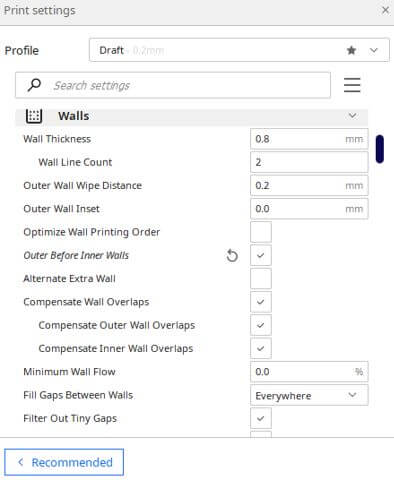
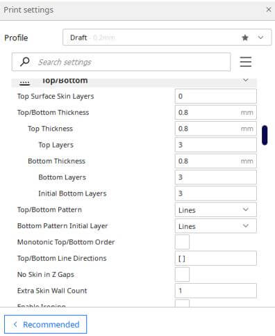
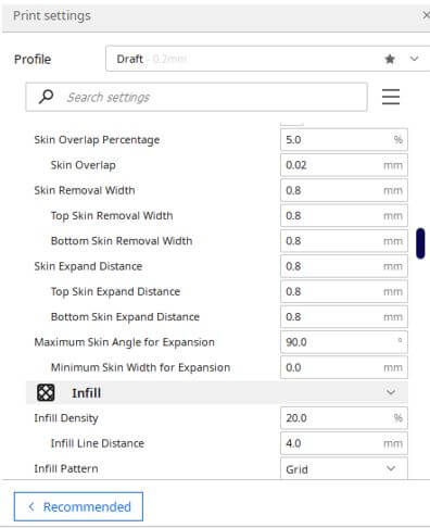
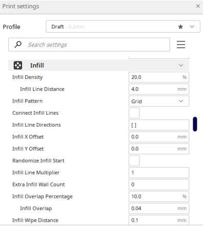
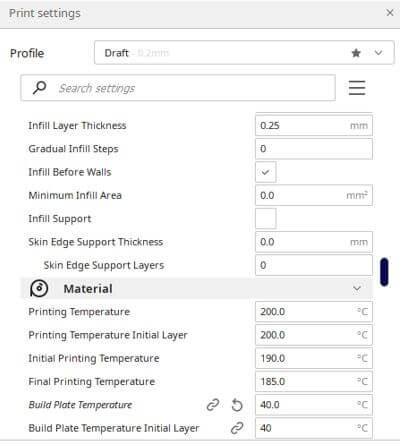
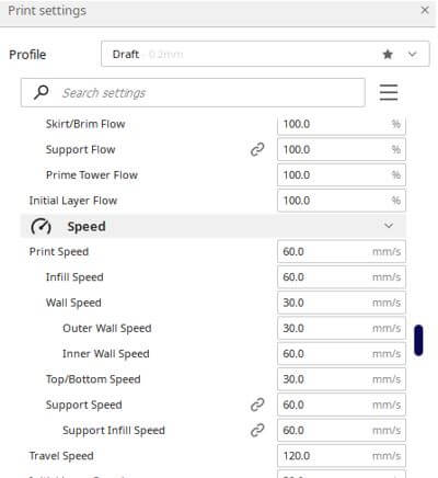
Before printing we must set all the printer values:


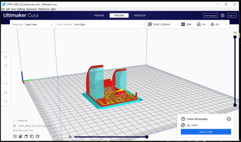
We downloaded the image "3D_printer_test_mini" from the following link: click here and we made the test print with these characteristics. To preview the image under the given characteristics we rotate by pressing the right mouse button and rotating the pointer we can view the object from different angles. Then we insert the file saved in an SD memory into the 3D printer under those conditions, giving us an approximate printing time of 1 hour 49 minutes with 29 grams.
The images show the panel of our printer and the parameters with which it starts printing:
- The hooter is at a temperature of 199 °C
- Base (bed) platen is heating to 61°C
- The percentage of progress is at 80%
- Z height is at 0.10 mm


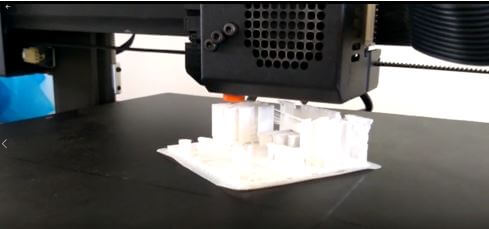
Some screenshots of the print:

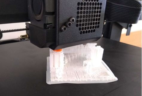
Finally, it is thus clean of all support.
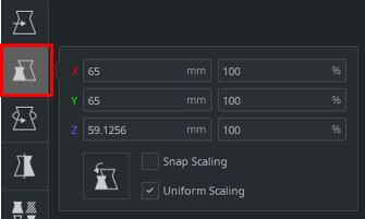
We proceed to make the second impression with the following characteristics and with the following size at 100.
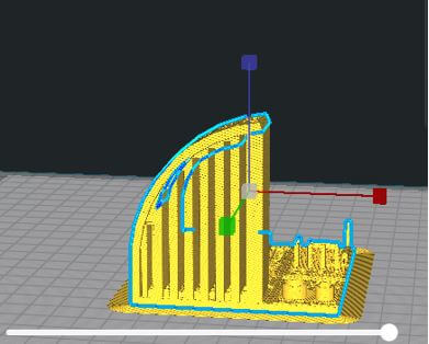
After segmentation, it tells us that printing will take 5 hours and 27 minutes and 31 grams will be used. The print preview is displayed with the support option activated.
Finally, we save the file in the SD and then we print it with the indicated characteristics.

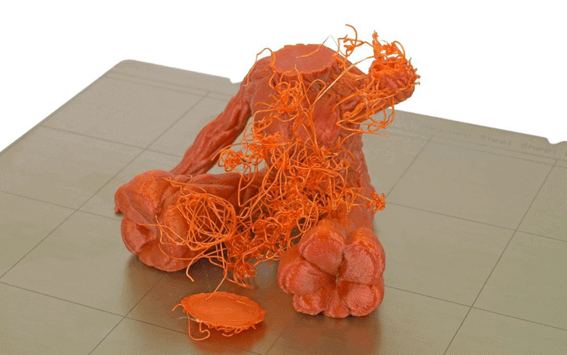
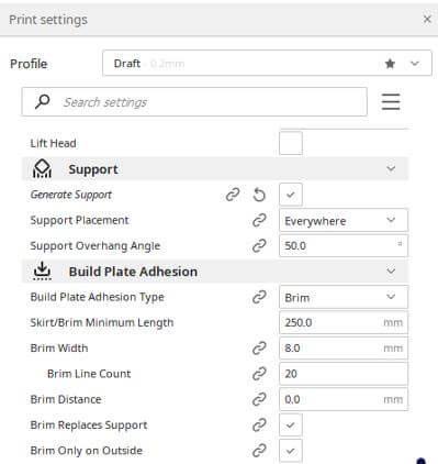
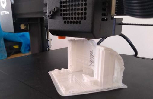
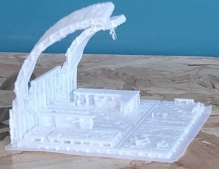
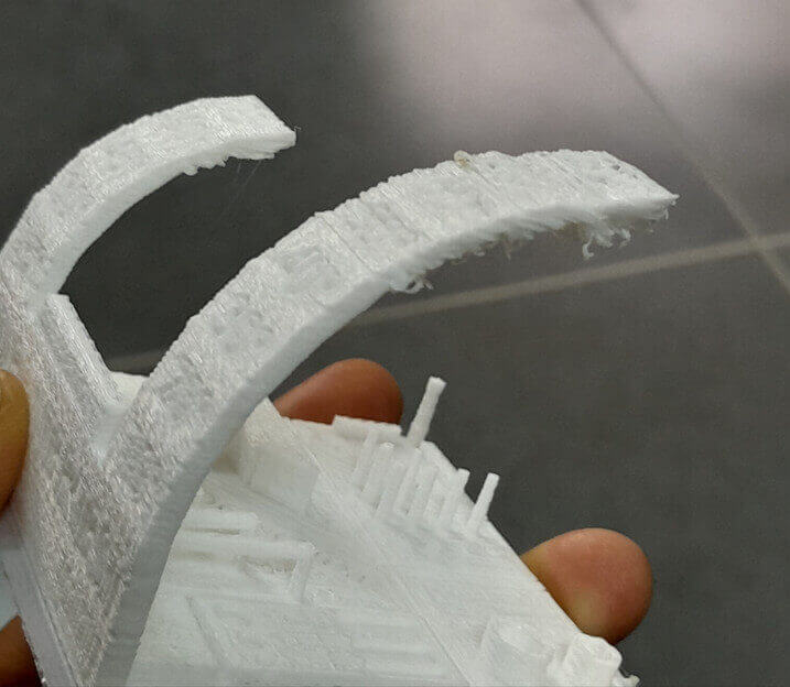
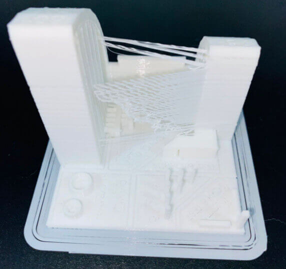
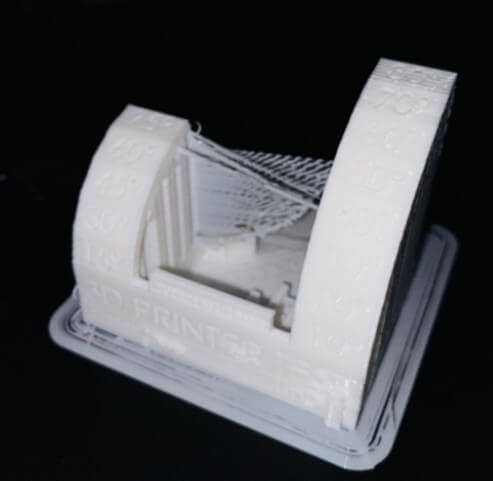
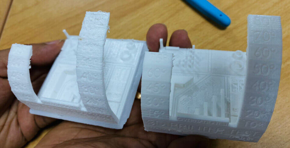
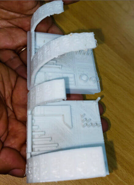
The print was made at 80% infill, without support and with adhesion. It can be seen that the piece without support deforms; on the right arch from an inclination of 50° and on the left arch from an inclination of 60°.

The minitest impression was made at 100% fill with a 0.2 profile and support and adhesion were added in settings. In addition to taking into account the rest of the print settings as we can see in the images.


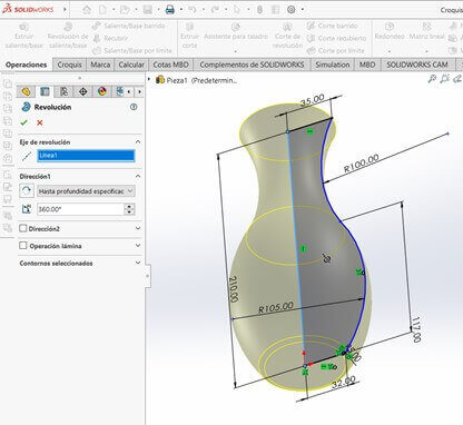
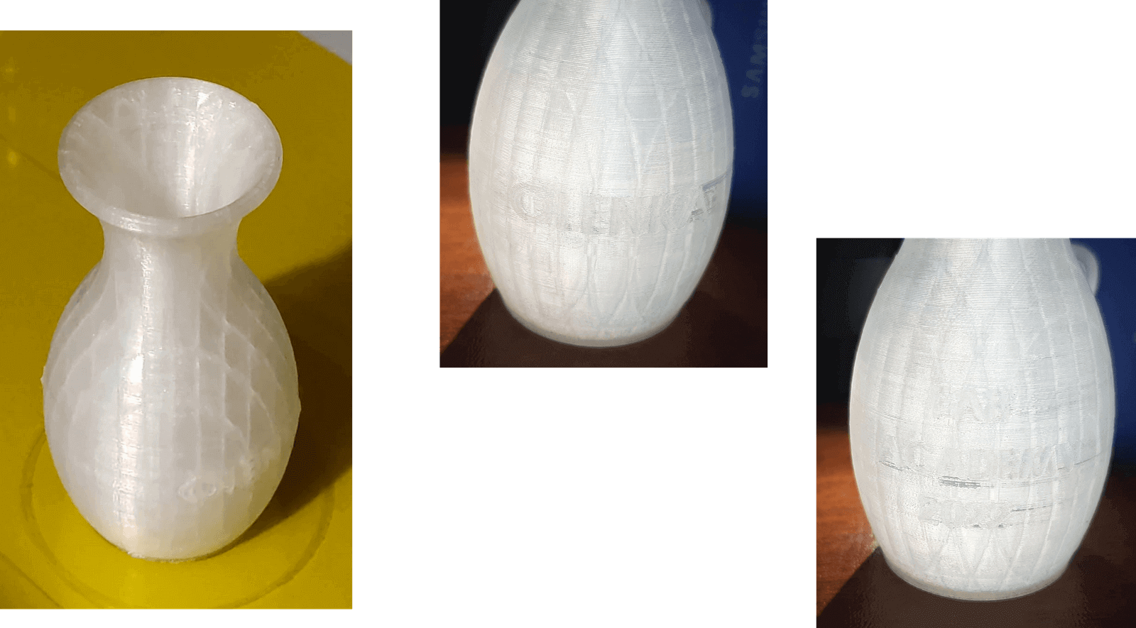
Using Solidwors I decided to make a personalized vase, since they usually come in a single design and adding some more detail can increase their cost; for the design of the vase I follow a YouTube tutorial: Vase in Solidworks.


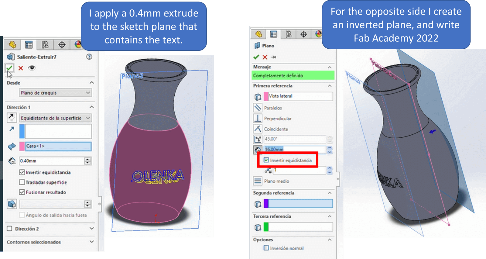
Now I proceed to personalize it by placing my name “OLENKA” and “FAB ACADEMY 2022”.

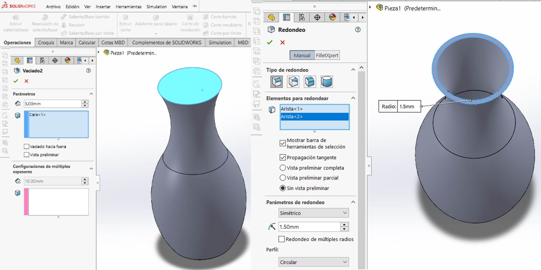
Procedure


Finally, once the vase is finished, I save the file with the STL extension, so that I can later open it in the Cura software.

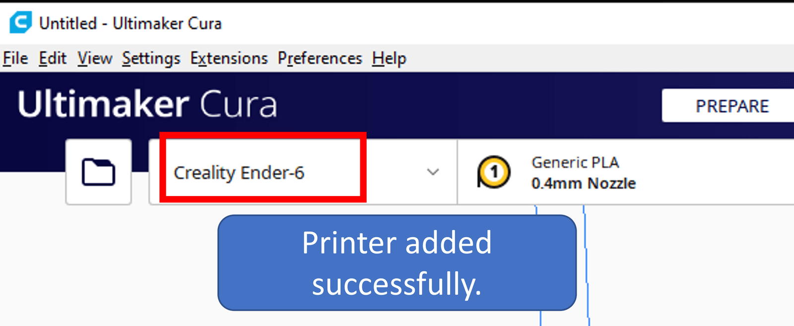
For the 3D printing of the vase, an ENDER 6 model printer of the CREALITY brand has been used. This must be taken into account when choosing the printer in the Cura software.

We correctly locate the vase with the turning tool.

With the recommended settings shown, you get the following:

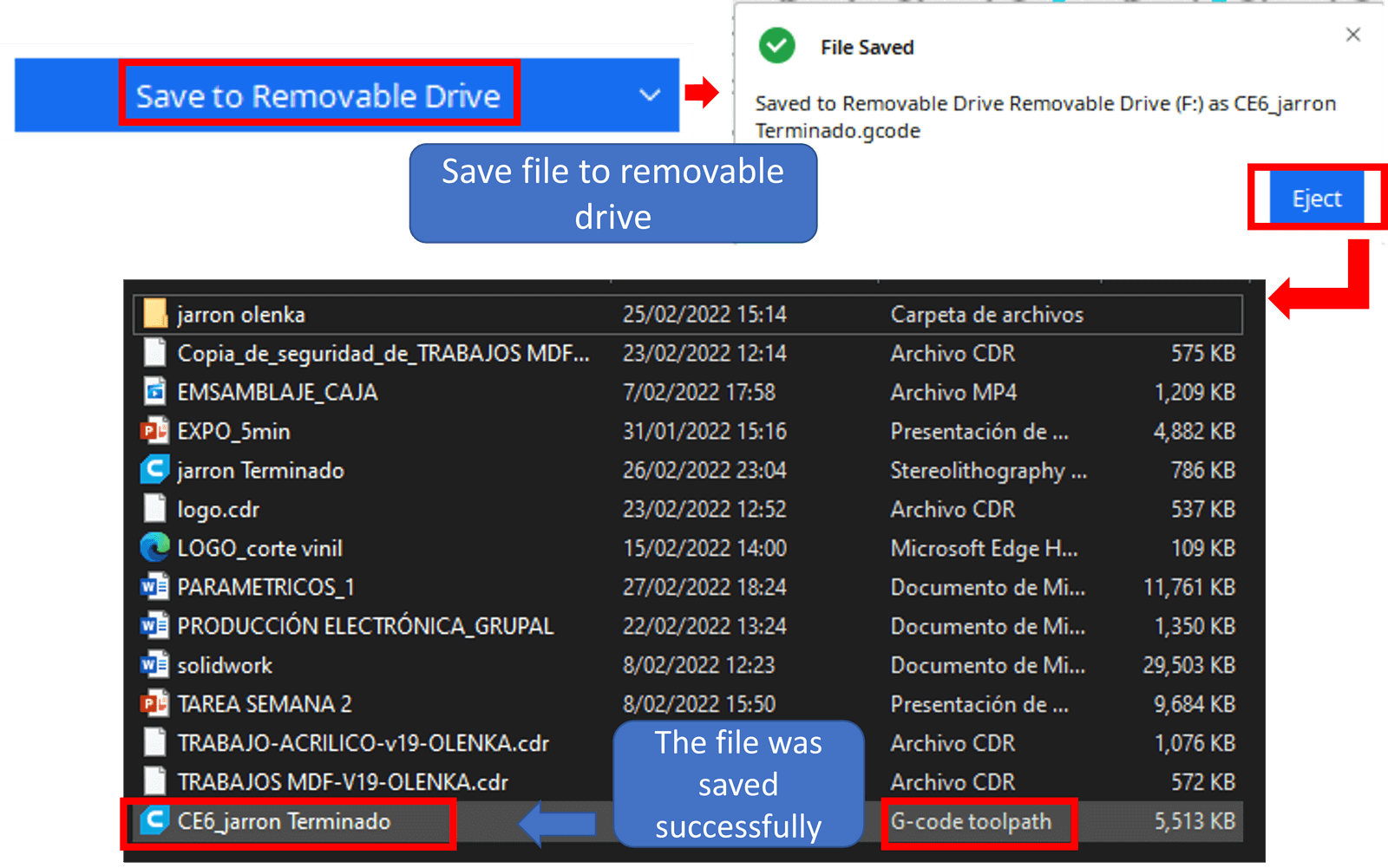
Now we proceed to save the file that will be transferred to the 3D printer. The priest saves the file in G code.
Finally, this is the printed vase.
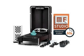
We have in our laboratory a Matter & Form Mfs1V2 scanner which works with the MFStudio software. The main features of the scanner are:
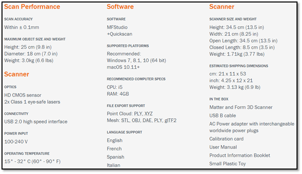
To scan an object we must first turn on the scanner and connect it to the computer, then we must take into account the following:


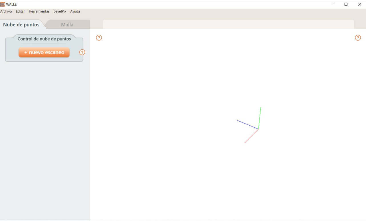
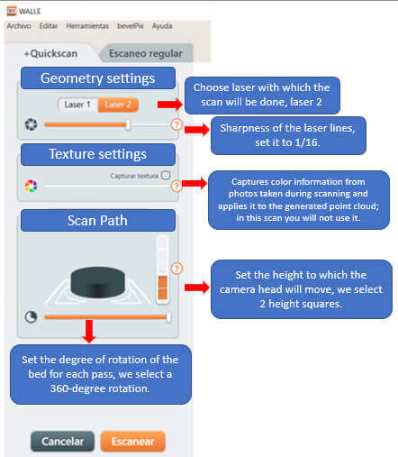
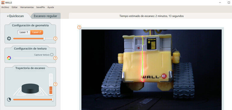
Step 4: Choose the +Quickscan option. It opens a window where the geometry configuration, the texture configuration and the scanning path are determined.
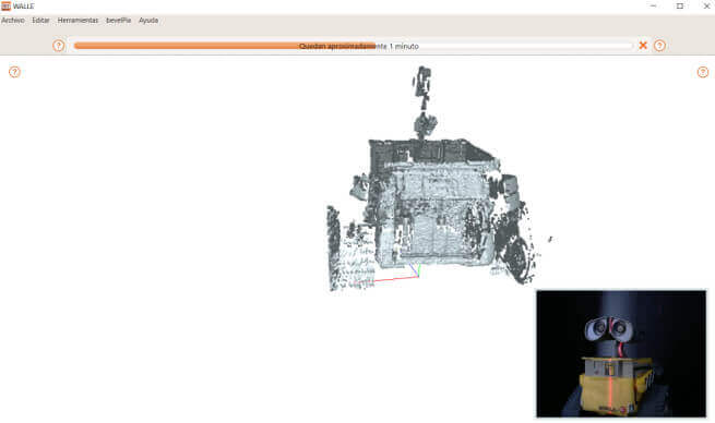
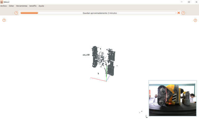
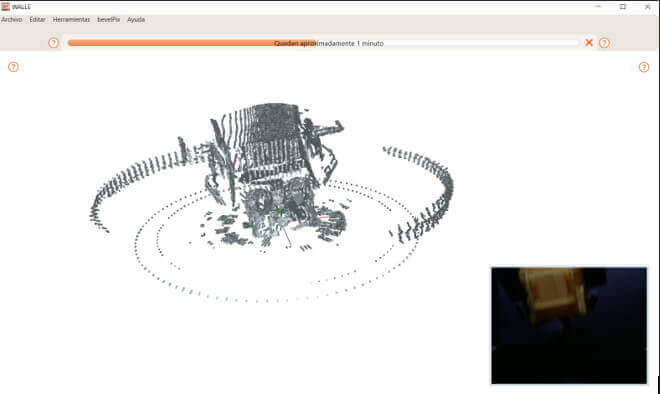
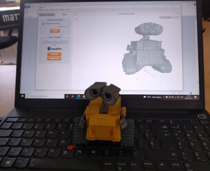
Step 5: Once the parameters are set, we scan the object in different positions for a more accurate reconstruction of the image.
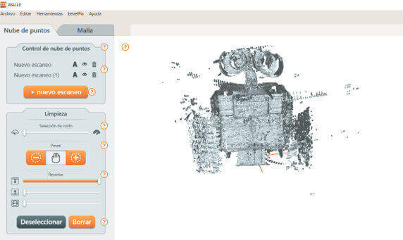

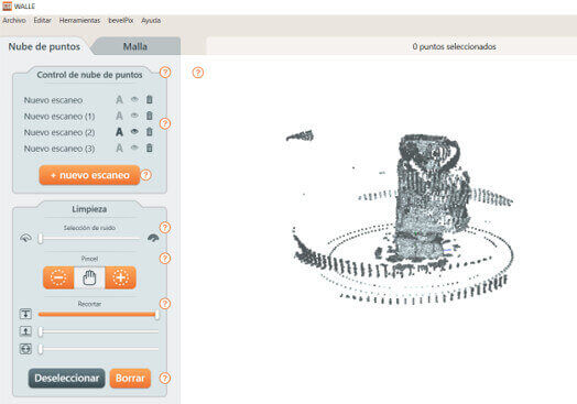
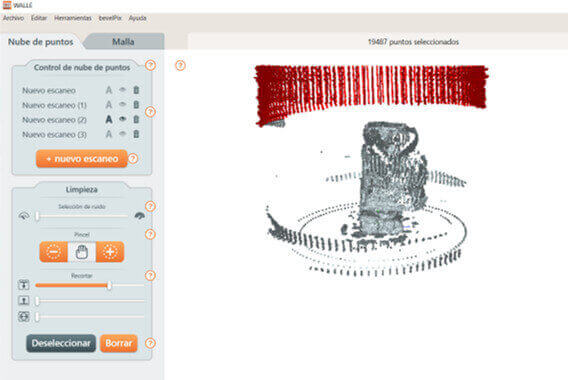
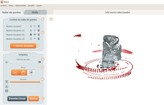
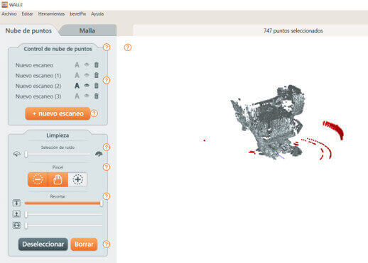
Step 6: The scanner can pick up unintended spots caused by reflections on the object's surface or background movement. That is why it is necessary to clean these unwanted points, for this in the Point Cloud tab in the "Point Cloud Control" option we enable each scan one by one to perform the respective cleaning by selecting everything that does not form part of the object then click delete.

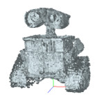
Step 7: After cleaning each scanned image, we must align the captured images in different positions to obtain a more complete final image.
Step 8: Now we must perform the meshing of the project, according to the level of meshing that we assign to it, it will present a greater level of detail. The images show a mesh level 0, 6, 8, 9 and 11. We chose mesh level 9 since the image is better appreciated.


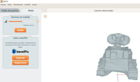
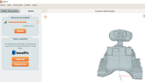
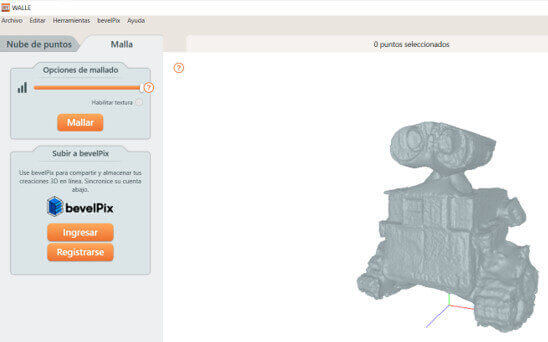
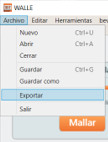
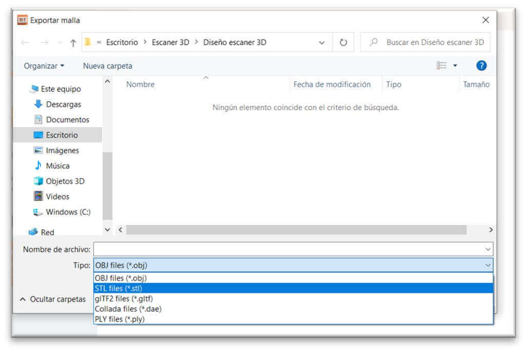
Step 9: After choosing the mesh with which we will work, we proceed to export our project, choose the STL format, put a name and click save. And now we have our file ready.
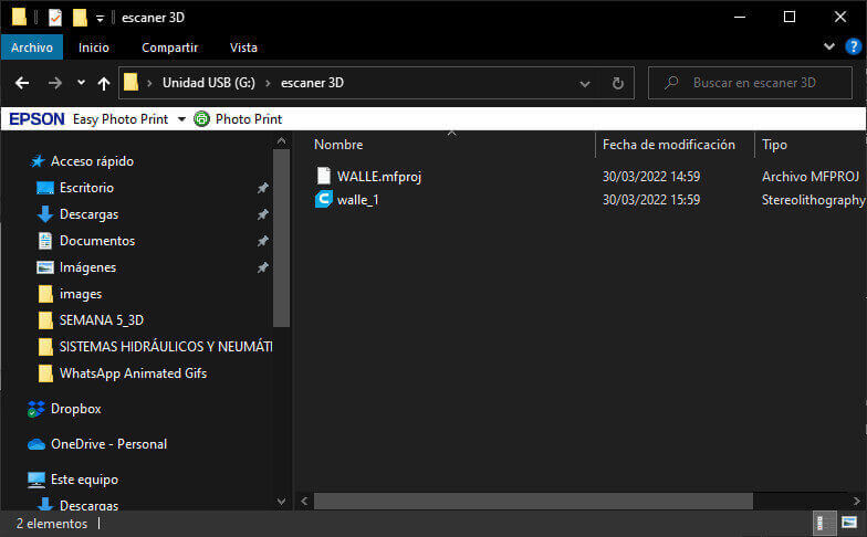
Here are some images and a video of the Wall-E toy scan.

FILES:
-
3D printing and scanning_1
- 3D printing and scanning_2
What I learned:
created with
HTML Website Builder .