
In this section we list the activities to be solved in the following table:
| Checklist | Estatus |
|---|---|
| Linked to the group assignment page | Finished |
| Documented what you learned from browsing through a microcontroller datasheet. | Finished |
| Described the programming process(es) you used | Finished |
| Included your source code | Finished |
| Included ‘hero shot(s)’ | Finished |
- Compare the performance and development workflows for other architectures
- Document your work to the group work page and reflect on your individual page what you learned
I will also do this assignment individually.
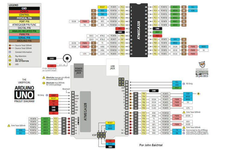
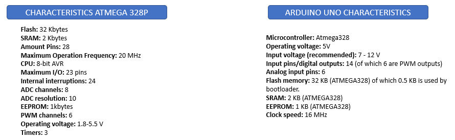
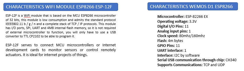
For this assignment I will work with the ATMEGA328P microcontroller that we can find in an ARDUINO UNO and with the ESP8266 microcontroller that is the basis of the WEMOS D1 ESP8266 board. Let's learn more about both microcontrollers.
 Features
 Programming environment
To program the Arduino Uno card we must first install the Arduino IDE, I leave you here the download link is very easy to install. The open-source Arduino Software (IDE) makes it easy to write code and upload it to the board. This software can be used with any Arduino board. The latest version is Arduino IDE 2.0.3. I have version 1.8.14 installed.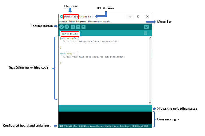

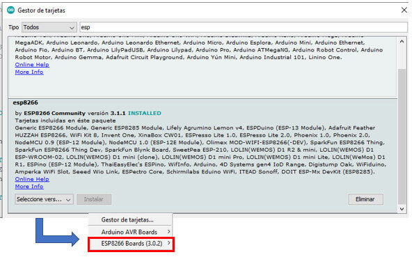
Wemos D1 can be programmed using the Arduino IDE. In this way, we can take advantage of the code made for arduino and take it to this card easily. To work with the WEMOS D1 ESP8266 card with the Arduino IDE, we must first configure and install the necessary libraries and drivers so that our card can be recognized and programmed. I based it on a YouTube video, he left the link here.
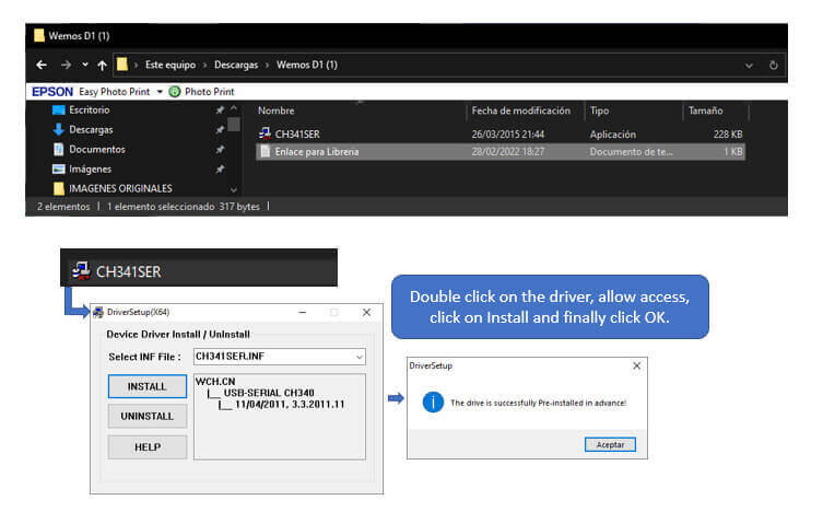
After downloading and decompressing the files, we proceed to install the driver.
Now we enter, from the Arduino IDE, the link in the card additional URLs manager.

We install the ESP8266 card library.

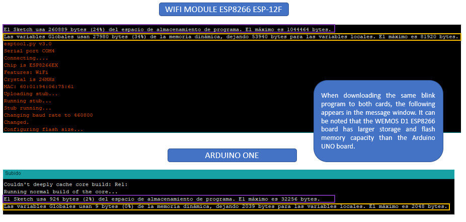
I programmed both cards with the same "BLINK" program, which we can find in the examples provided by the Arduino software (we must take into account that when selecting ESP8266 we must choose the examples for that card). When downloading the programs the following appears:
As this card is known to integrate an ESP8266 Wi-Fi module, I did not want to miss the opportunity to test the Wi-Fi module. Searching the internet I found a program that allows you to control the on and off of a led over the internet, based on that I made my program.
I leave the original code here. This program was used with a NodeMCU card with ESP-M2 wifi module, based on the ESP8285 SoC according to this video; but configuring by software it can be used with the WEMOS D1 ESP8266 card.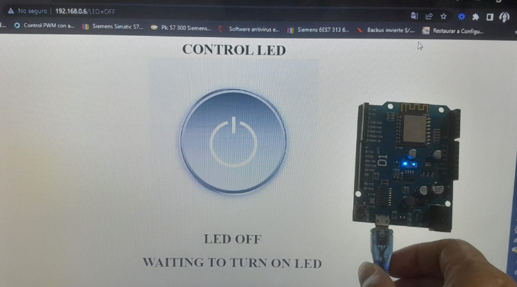
Once we load the program to the card, we enter the serial monitor to obtain information on the address of the internet page that we must access to control the on and off of the led, if the information does not appear, it is enough to press the button reset the card and the information will appear. Do not forget that it is necessary that we place the serial communication at 115200 baud.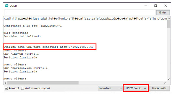
I searched for the on/off images that appear on the internet and copied the address of the image, but since it was too long, I shortened the URL with the following online program "Acortar.link URL", and it worked correctly.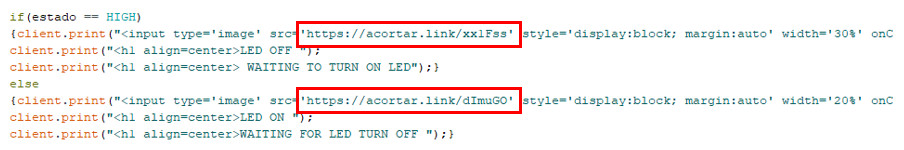
Videos of what has been done:
This week I have to review the technical data sheets of microcontrollers from different families, let's see what we find.
This card is based on the RP2040 microcontroller which has a 32-bit structure. It is a low-cost, high-performance microcontroller board with flexible digital interfaces.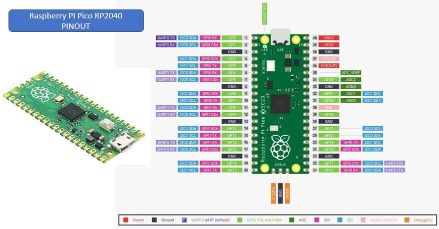
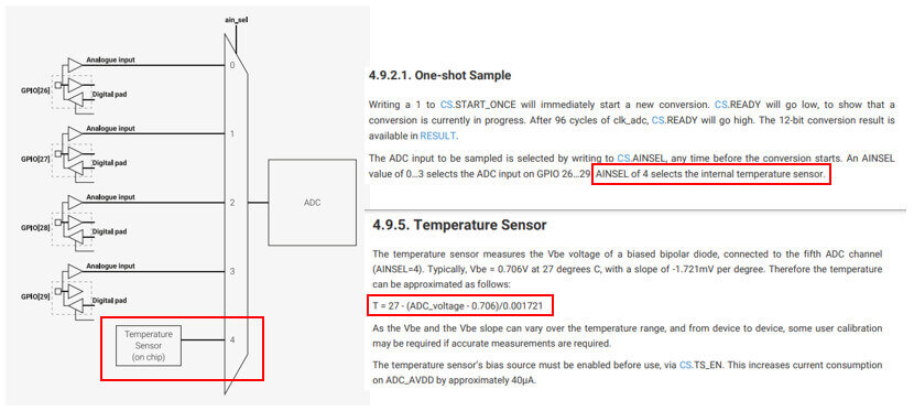
Among its main features, it has an internal temperature sensor, it sounds interesting.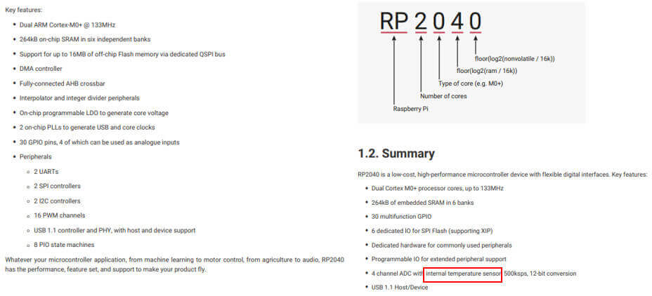
The Raspberry Pi PICO platform can be programmed with either MicroPython or C/C++, with MicroPython being the easiest way to get started. It is also possible to program the PICO from the Arduino IDE. I decided to work with MicroPython.
According to what I could read on the internet I need to install MicroPython firmware for Raspberry Pi Pico and the Thonny Python IDE to program the Raspberry Pi PICO RP 2040 board.
Downloading Thonny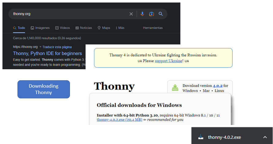 Installing Thonny
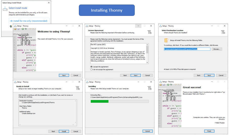 Programming environment of the Thonny IDE
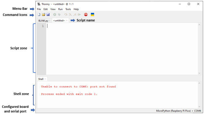
Installing MicroPython firmware for Raspberry Pi Pico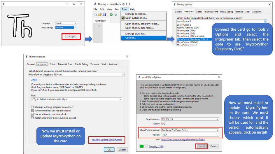
Checking connection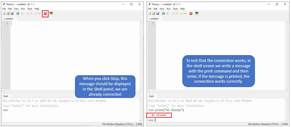
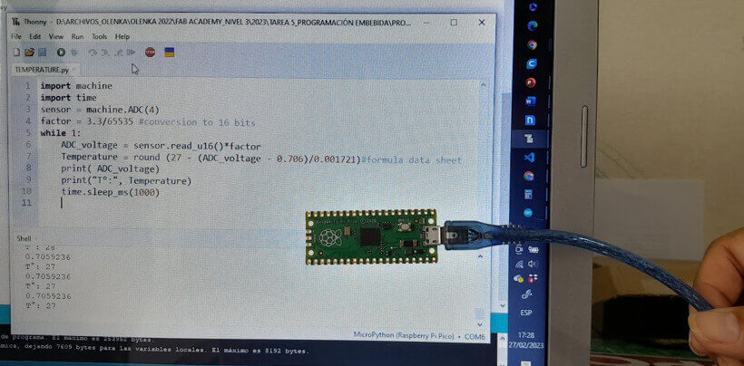
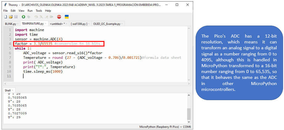
The Raspberry Pi PICO RP 2040 among its features presents an internal temperature sensor. To program it using this sensor I used the formula found in your data sheet, keeping in mind that setting an AINSEL of 4 selects the internal temperature probe.
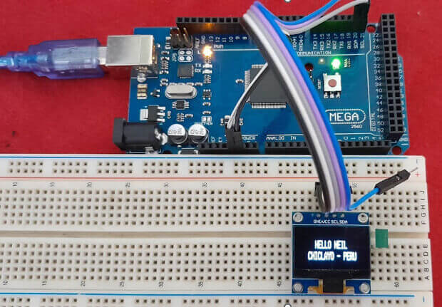
Board based on the ATmega2560 microcontroller with an 8-bit structure. Let's see some of its features.
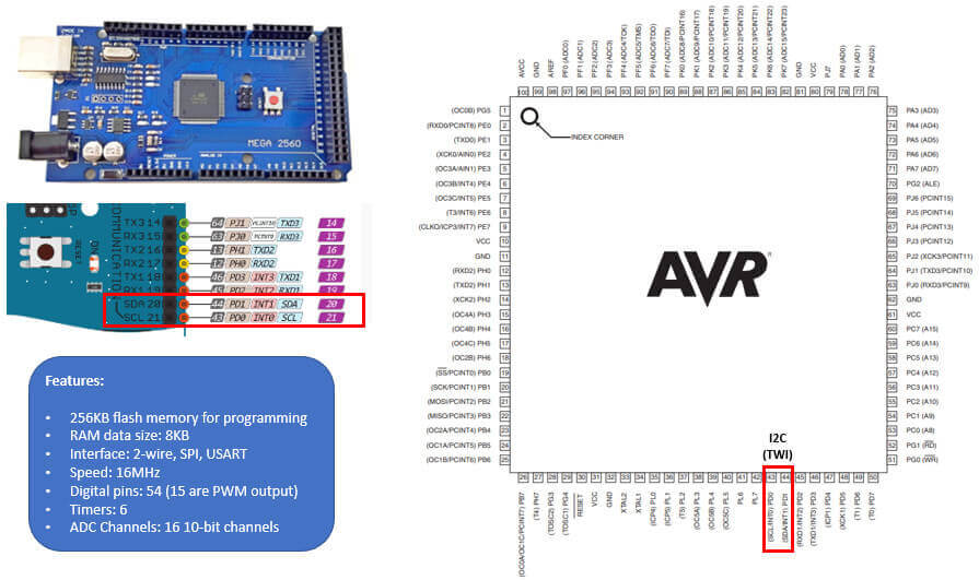
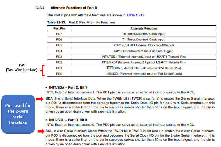
In its data sheet it indicates that it has two pins for the 2-wire serial interface, I will use these pins to connect a 0.96'' I2C 128*64 SSD1306 OLED screen.
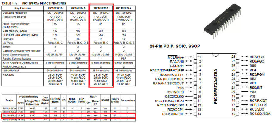
In my student days, PIC microcontrollers were the most used microcontrollers; with its CPU architecture RISC (Reduced Instruction Set Computer), set of 35 instructions. PICs are very versatile since they contain all the components to perform and control a task.
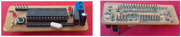
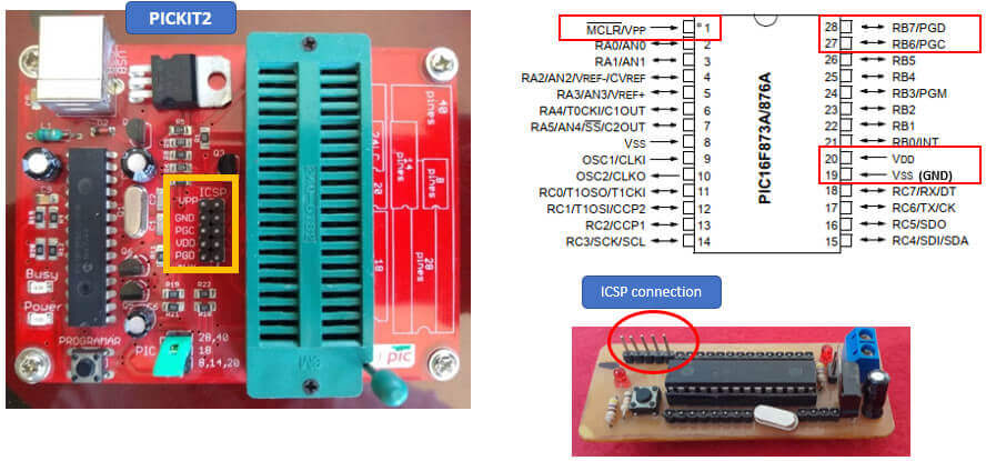
This is my trainer board made with the 16F876A microcontroller.
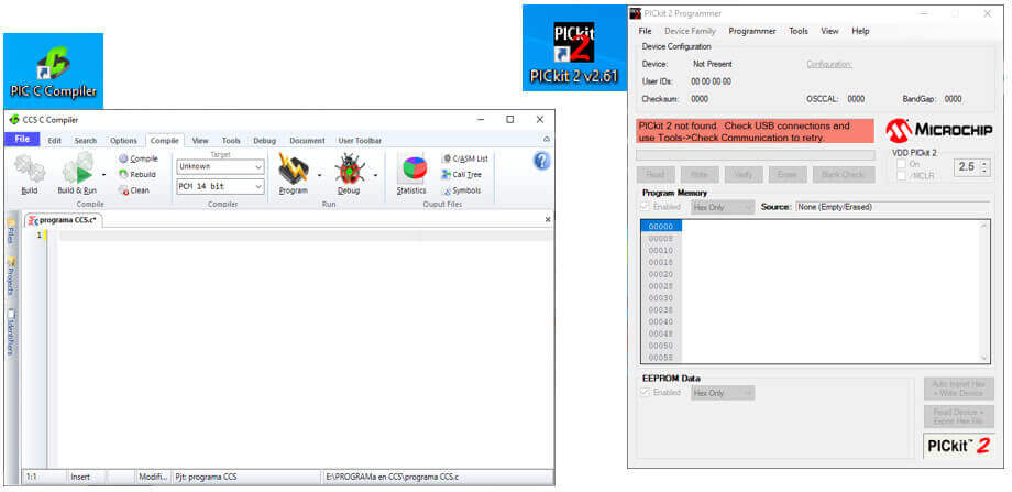
To program the PIC 16F876A, I used the PIC C COMPILER software to make the program and the PICkit 2 Programmer software needed to write a program on a PIC using the PICkit2 programmer.
This PIC has certain pins that allow it to be programmed through an ICSP (In Circuit Serial Programming) connection. This technology included in all PIC microcontrollers makes it possible to reprogram them without it being necessary to remove them from their application circuit to take them to the programmer. The signals connected between the PIC and the programming device to write, read and verify the program are the following:
We open the program, click on File – New – Source File; We put the name "program" and click on save. We proceed to carry out the program in the PIC C Compiler environment, as shown below: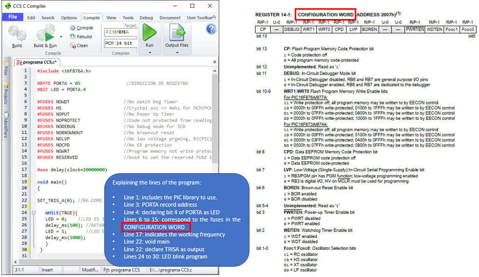
Do not forget: when programming a PIC, to declare a pin as an input the corresponding bit must be set to 1 and to declare a pin as an output the corresponding bit must be set to 0.
Finally we compile the program and if there are no errors we are ready to save the PIC. When compiling the program, a file is created, CCS program with HEX extension, which must be imported from the PICkit 2 Programmer software to record the PIC. We connect the programmer through the USB port and proceed to record the PIC.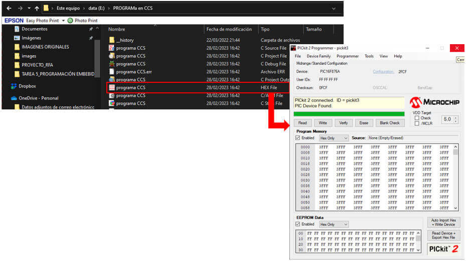
The Attiny85 is a low-power, high-performance 8-bit AVR microcontroller, its main features are described below:
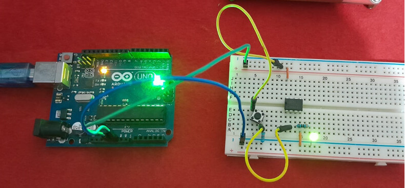
To program this microcontroller I will use the SPI interface (Serial Peripheral Interface) on the MOSI (PB0), MISO (PB1), SCK (PB2), RESET (PB5) pins, as detailed in its PINOUT.
PWM: I will place a led on physical pin 3 (PB4) which, according to its datasheet, has a PWM output that will allow me to regulate its brightness. And on physical pin 2 (PB3) a button.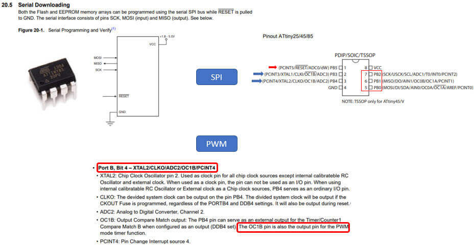
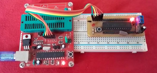
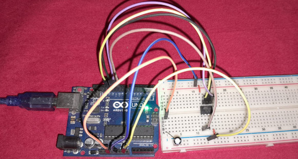
I don't have this microcontroller on any board, but I still wanted to program an ATtiny85 microcontroller, so I used an Arduino Uno board and an ATtiny85 microcontroller with DIP package.
Next, I show an image of the pinout of the Arduino Uno based on the ATMEGA328P microcontroller, giving importance to the following physical pins that will allow me to program the ATtiny85 by SPI: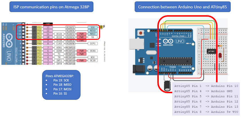
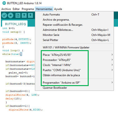
To carry out the programming, we must first convert the Arduino Uno board into an ISP programmer, for this we go to File and in "Examples" select "Arduino ISP". We connect our card, enter "Tools" and verify that it is configured as follows: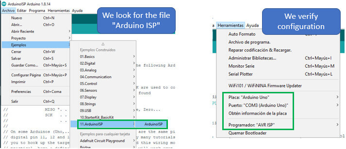
Compile and download the “Arduino ISP” program to the Arduino Uno board and you are ready to program the ATtiny85.
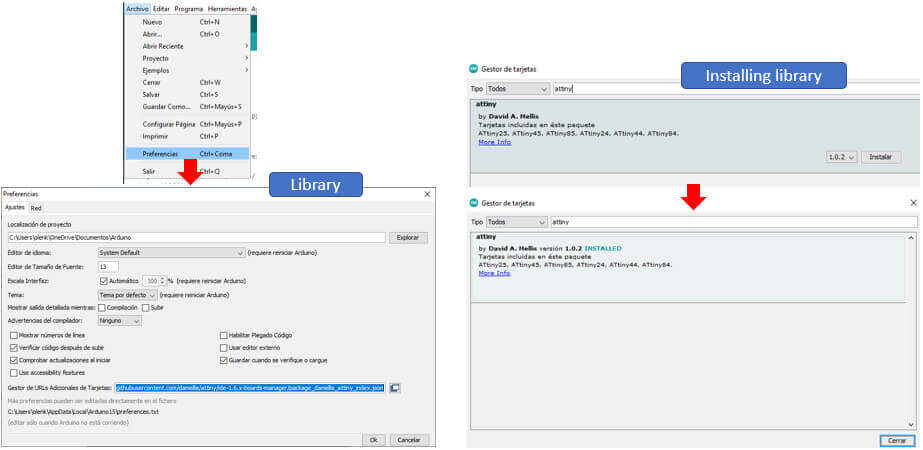
In order to program the ATtiny85 microcontroller with the Arduino IDE, it is necessary to install the corresponding library, as indicated below:

created with
HTML Designer .